 Kagan Sogut
 Burcu Ercan
- Department of Civil Engineering, Kilis 7 Aralık University, Kilis, Türkiye
The existing web opening created in shear span of concrete deep beams due to reasons such as accommodating utility pipes or cables resulting in a reduction in a load bearing capacity. The overall load bearing capacity can be directly affected by the extent to which arch action is interrupted in the direct load transfer to the support. Strengthening solutions have therefore appeared to enhance the load bearing capacity. However, the concrete deep beams have yet to be strengthened with the Deep Embedment (DE) Fibre Reinforced Polymer (FRP) technique. This study aims to examine the behaviour of high-strength concrete deep beams with openings, taking into account both the unstrengthened condition, and the strengthened condition with DE Carbon FRP (CFRP) bars. The finite element (FE) model was established and validated against experimental results. The FE model gave accurate predictions with a mean value of 0.97. The validated model was then used to further examine the effects of concrete strength, shear span-to-effective depth (a/d) ratio, web opening dimensions, and web opening location on the unstrengthened behaviour. Moreover, the applicability of DE CFRP bars was investigated by examining the shear force–deflection response, FRP bar diameter, and FRP bar configuration. Increasing the concrete strength from 40 to 100 MPa resulted in an improvement in shear force capacity of up to approximately 45.5%. An increase in the a/d ratio from 1.08 to 2.7 resulted in a reduction in the shear force capacity by about 50%. The findings showed that the load transfer to the support through direct compression was increasingly disrupted in concrete deep beams as web openings became larger. Shear resistance was directly affected by the position of the web opening. The position of web opening affected the continuity of the load path from the load application point to the support. The use of CFRP bars instigated an enhancement of the shear force capacity of up to 33.8%. Shear resistance also increased as bar diameter was increased. Finally, the design guidance predictions were evaluated, and it was found that the design guidance significantly overestimated the DE CFRP-strengthened shear force capacity.
1 Introduction
Concrete beams with a shear span-to-effective depth (a/d) ratio of less than 2.5, which are subjected to higher shear forces and lower bending moments, exhibit a complex load transfer mechanism (Kani, 1964). These beams are classified as deep beams, for which classical beam theory is not applicable (Kani, 1964; Kani, 1967). This complex mechanism can become even more intricate when web openings are introduced to accommodate utility pipes or cables (Yang et al., 2003; Yang et al., 2006). However, when the openings created in the beam web interrupt the load transfer, which occurs through direct compression toward the support, the shear force capacity of beams with web openings is significantly reduced (Yang et al., 2006). Consequently, there is a growing demand for shear strengthening methods to improve the performance of deep beams by exhibiting such discontinuities. In recent years, fiber-reinforced polymer (FRP)-based reinforcement systems have attracted attention as effective and innovative solutions for extending the service life of concrete beams (Teng et al., 2003; Triantafillou, 1998; Wu and Eamon, 2017; Sogut et al., 2021; Caro et al., 2023; Dirar et al., 2024; Dirar et al., 2025). Carbon FRP (CFRP)-based reinforcement, in particular, has proven effective in improving shear strength by providing an alternative to traditional reinforcement (i.e., steel), because of its low weight, resistance to corrosion and higher tensile strength (Caro et al., 2023; Dirar et al., 2025; Sogut et al., 2021; Wu and Eamon, 2017). The Deep Embedment (DE) FRP technique (Valerio and Ibell, 2003; Valerio et al., 2009) known alternatively as the Embedded Through Section (ETS) method (Chaallal et al., 2011; Mofidi et al., 2012; Bui et al., 2020), was introduced to resolve issues present in externally bonded (EB) (Chaallal et al., 2011) and near-surface mounted (NSM) FRP techniques (De Lorenzis and Nanni, 2001). The DE FRP technique is particularly useful in situations where access to the flange and/or web is restricted (Valerio and Ibell, 2003; Valerio et al., 2009). Moreover, it eliminates time-consuming surface preparation (e.g., Valerio and Ibell, 2003; Valerio et al., 2009; Chaallal et al., 2011; Mofidi et al., 2012; Bui et al., 2020; Sogut et al., 2021; Caro et al., 2023; Dirar et al., 2024; Dirar et al., 2025). Debonding can be a serious problem if a proper anchorage system is not applied (Chaallal et al., 2011). Chaallal et al. (2011) compared three techniques and concluded that the DE FRP technique was superior.
The behaviour of concrete beams with existing web openings has yet to be fully understood. For example, the effect of concrete was both experimentally and numerically investigated (Yang et al., 2003; Khalil et al., 2004; Yang et al., 2006; Hu and Tan, 2007; Yoo et al., 2013; Liu and Mihaylov, 2020; Lu et al., 2020; Saleh et al., 2023). The correlation between concrete strength and ultimate load capacity was found to be positive. Concrete strength is well known as a significant parameter affecting the behaviour of concrete elements (Yang et al., 2024; Liu et al., 2025; Shi et al., 2025). The concrete strength improved the capacity at which first cracking occurred, but it did not affect the shear failure mode of deep beams with openings (Khalil et al., 2004). The rate of increase in shear resistance with increasing concrete strength was higher in solid beams than in those with web openings (Yang et al., 2006). The dimensions of web opening together with its location in the beam were examined by conducting both experimental and numerical studies (Khalil et al., 2004; Yang et al., 2006; Guan and Doh, 2007; El Maaddawy and Sherif, 2009; Campione and Minafo, 2012; Alsaeq, 2013; Yoo et al., 2013; Mohamed et al., 2014; Jasim et al., 2018; Ibrahim et al., 2018; Liu and Mihaylov, 2020; Lu et al., 2020; Mabrouk et al., 2022; Saleh et al., 2023). The location and web opening dimensions had a significant impact on the shear resistance. Increasing opening dimensions led to an increase in the crack width (Khalil et al., 2004). The deflection was significantly affected by the web opening dimensions once cracks appear (Yang et al., 2006). It was obtained that the variation between shear strength and opening dimensions exhibited an inverse relationship. For example, the ultimate load capacity decreased by 34% when the web opening depth was increased (Yang et al., 2006). The location of the web opening also affected the behaviour. For instance, the shear resistance reduced by up to 30% once the web opening was positioned into the shear span (Campione and Minafo, 2012). Shear resistance can be directly affected by the extent to which arch action is interrupted in the direct load transfer to the support. The shear resistance depends on the position of the web opening, which affects the continuity of the load path from the load point to the support (Yang et al., 2006; Hu and Tan, 2007; Yoo et al., 2013; Jasim et al., 2018). Although design codes included in formulations for solid deep beams, the design of those with web openings has not yet been included design codes (Yoo et al., 2013; Ibrahim et al., 2018). The behaviour of concrete deep beams with existing web openings and high strength concrete has not yet been completely examined (Yang et al., 2006; Yoo et al., 2013; Hassan et al., 2019; Ismail et al., 2021; Erfan et al., 2024; Shabanlou et al., 2025). Moreover, the strengthening of deep beams with web openings is still an issue, although studies on this issue have been conducted (El Maaddawy and Sherif, 2009; Maaddawy and El-Ariss, 2012; Chin et al., 2014; Abdul-Razzaq et al., 2017; Nie et al., 2020; Saleh et al., 2023). But the implementation of DE technique in deep beams with existing openings has not yet been done. The aim of this paper is to research the behaviour of high-strength concrete deep beams with openings, taking into account both the unstrengthened condition, which has not yet been fully understood, and the strengthened condition with embedded CFRP bars, which has not been studied yet. To accomplish these, a nonlinear finite element (FE) model was established and thoroughly validated against experimental data in the published literature, which enables an opportunity for carrying out further parametric studies. Numerical analyses based on a validated FE model serve as an effective tool to predict the behaviour of concrete elements (Fawzy et al., 2024; Gong and Li, 2024; Luo et al., 2025; Muhammad, 2025; Sogut et al., 2025; Yang et al., 2025; Zou et al., 2025). The parameters to understand the unstrengthened behaviour were concrete strength, a/d ratio, web opening dimensions, and location of web opening. For the first time, the applicability of embedded CFRP bars to strengthen concrete deep beams with web openings was indicated. To understand the strengthened behaviour, shear force deflection response, FRP bar diameter and FRP bar configuration were considered. Moreover, the predictions of The Concrete Society, (2012) for strengthened behaviour were also evaluated. The comparison of code predictions is important since it can shed light on future work (Jiang et al., 2025). This paper contributes new knowledge to the literature on the applicability of embedded CFRP bars for the shear strengthening of concrete deep beams with web openings and provides a parametric study on unstrengthened deep beams with web openings through the development and validation of a detailed nonlinear FE model. Moreover, this study highlights the need for a design guideline to predict the behaviour of DE FRP-strengthened deep beams with existing web openings.
2 Methodology
The nonlinear FE model was established applying the VecTor2 (Wong et al., 2013) software, which has been successfully employed by many researchers to model concrete members (e.g., Palermo and Vecchio, 2007; Dutta et al., 2022; Dutta et al., 2023; Ibrahim et al., 2023; Dirar et al., 2025; Sogut, 2025). The software utilises the formulations of the Modified Compression Field Theory (MCFT) (Vecchio and Collins, 1986) and the Disturbed Stress Field Model (DSFM) (Vecchio, 2000) to predict the behaviour of RC members. Moreover, it incorporates a smeared, delayed rotating crack model to analyse the behaviour of RC elements. Details on the established FE model are described in the following sections. Further details regarding the theoretical framework are provided in the VecTor2 User’s Manual (Wong et al., 2013).
2.1 Specimens
The concrete deep beams with existing web openings tested by Yang et al. (2006) were used to validate FE model, which is detailed in the following sections. As shown in Figure 1, a four-point bending configuration was used to test the beams. The tested beams had a height of 600 mm (mm) and a width of 160 mm. The shear span was either 300 mm or 600 mm, resulting in an a/d ratio of approximately 0.54 or 1.08, respectively. The tension reinforcement contained three 19 mm diameter steel bars, which were welded to steel plates at both ends to prevent anchorage failure. The tension reinforcement ratio was hence set to approximately 0.96%. The deep beams with existing web openings were initially designed without steel shear links. The geometrical details together with material properties of the tested beams are listed in Table 1. Rectangular-shaped web openings were created in each shear span (Yang et al., 2006). The width and depth of the web openings are denoted by x and y, respectively, in both Figure 1 and Table 1. The distances from the web opening to the support and the bottom of the beam are denoted by k and m, respectively, in both Figure 1 and Table 1. In addition, the shear span (a) of each beam is also provided in Table 1. The tested beams had a cylinder compressive strength (fc) of either 52.9 or 80.4 MPa. The yield strength of longitudinal reinforcement was 420 MPa.
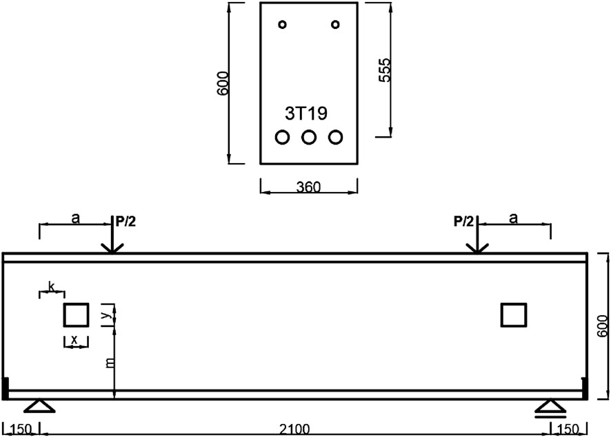
Figure 1. Details of tested beams (redrawn from Yang et al., 2006) (all dimensions in mm).
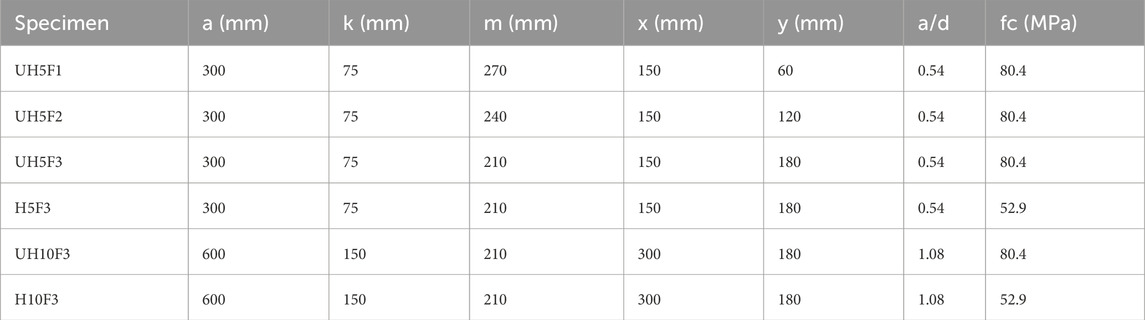
Table 1. Description of tested beams by Yang et al. (2006).
2.2 Material constitutive relations
To model the compressive behaviour of concrete, including both the pre- and post-peak (ascending and descending branches), the stress–strain curve developed by Thorenfeldt et al. (1987) was utilised (see Figure 2). This model was specifically developed to accommodate the behaviour of high-strength concrete (Wong et al., 2013). As shown in Table 1, the tested beams had concrete compressive strengths of either 52.9 or 80.4 MPa. The stress–strain curve proposed by Thorenfeldt et al. (1987) is therefore appropriate for modelling the compressive behaviour of the tested beams. Equation 1 gives the stress-strain curve.
where fci (MPa) denotes the concrete compressive stress at a given strain εci (mm/mm); fp (MPa) is the peak concrete cylinder compressive strength and εp (mm/mm) is the corresponding strain. The parameters n and k are given by Equations 2,3, , respectively.
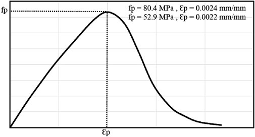
Figure 2. Concrete compression behaviour.
The concrete compression softening was simulated by Model B (Wong et al., 2013) in VecTor2 (Wong et al., 2013), which was originally developed by Vecchio and Collins (1993) for Thorenfeldt et al.’s (1987) stress-strain curve (Wong et al., 2013). The model is given in the following Equations from Equations 4–7.
where βd is the reduction factor for the concrete compressive strength, εc1 is the principal tensile strain, fc is the compressive strength of concrete, ε0 is the corresponding strain, and Cd and Cs are strain softening and shear slip factors, respectively.
The default Poisson’s ratio of concrete in VecTor2 (Wong et al., 2013) is 0.15. This value is also recommended as 0.15 by the CEB-FIP (1993). It was assumed that concrete exhibited linear-elastic behaviour under tension before cracking occurred. The post-cracking behaviour was modelled using a bilinear tension softening approach, adjusted by VecTor2 (Wong et al., 2013) from the CEB-FIP (1993). The default model in VecTor2 (Wong et al., 2013), which consists of three stages, was used to simulate steel bar’s behaviour. The first stage is linear elastic until the yield strength of 420 MPa. The second stage consists of a yield plateau at the yield strength. This is followed by the final stage, which represents strain hardening with an ultimate strength of 500 MPa. The interaction between steel bars and concrete was assumed to be perfectly bonded. As previously mentioned, the steel bars were welded to steel plates at both ends to prevent anchorage failure. Hence, the failure was not governed by the bond. Moreover, many researchers have successfully simulated concrete beams under static loading using this approach (Palermo and Vecchio, 2007; Godat et al., 2013; Qapo et al., 2016; Ibrahim et al., 2023).
2.3 Modelling
The plane stress rectangular element and truss element were employed to simulate the concrete and steel bars, respectively. The plane stress rectangular element had four nodes, while the truss element had two nodes. Each element had two degrees of freedom per node, resulting in a total of eight and four degrees of freedom for each concrete and steel bar element, respectively. The mesh size was 25 mm in each direction, which gave accurate predictions (see validation section). The selection of mesh size in each direction is consistent with the recommendations of VecTor2 (Wong et al., 2013). It is stated that the aspect ratio should not be greater than 1.5, as accuracy decreases when the shape transitions from square to rectangular. A typical FE model for beams with a/d ratios of 1.08 and 0.54 is shown in Figure 3. The software employs an iterative secant stiffness approach to produce an efficient nonlinear solution (Wong et al., 2013). An incremental displacement of 0.1 mm was applied to replicate the experimental loading, with a maximum of 100 iterations allowed per increment. Consequently, the solution converged successfully at every single displacement step.
Figure 3. FE model (a) a/d ratio of 1.08; (b) a/d ratio of 0.54.
3 Results and discussion
3.1 Validation
The concrete deep beams with existing web openings tested by Yang et al. (2006) were used to validate the FE model. Table 2 presents the ultimate load capacities of both the experimentally tested beams (P, Exp.) and the numerically simulated ones (P, FE), along with the corresponding midspan deflection values. The experimental load capacities were accurately simulated by the FE model. This was proved by predicting them with a mean ratio of 0.97. The standard deviation was also a relatively low value of 0.03. For deflection, the mean ratio of the predicted value (δ, FE) to the experimental value (δ, Exp.) was 1.15 and corresponding standard deviation value was 0.13.
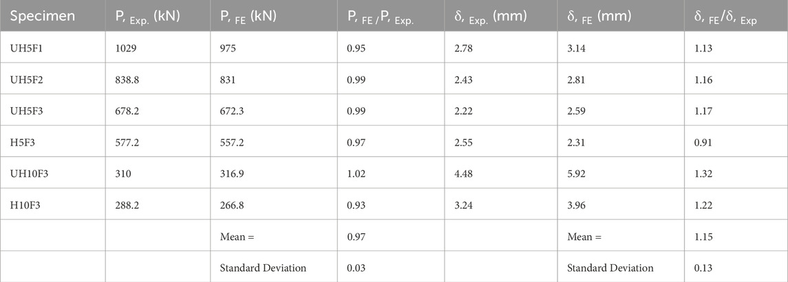
Table 2. Experimental and numerical results.
Figure 4 gives a comparison between the experimental load–deflection curves and those obtained from numerical simulations. The FE model predictions generally showed adequate agreement with the experimental results in terms of ultimate load capacity and both pre- and post-cracking behaviour. The predicted ultimate load capacities closely matched the experimental values. The initial stiffness of the FE-predicted curves, corresponding to the behaviour before cracking, also aligned well with the experimental curves, indicating that the material and geometric nonlinearities were appropriately represented. Except for specimen UH10F3, the post-cracking behaviour was also well simulated. Overall, FE model reliably reproduced the experimental load–deflection response. The accurately simulated structural behaviour of the tested deep beams supports the use of the model in further parametric studies.
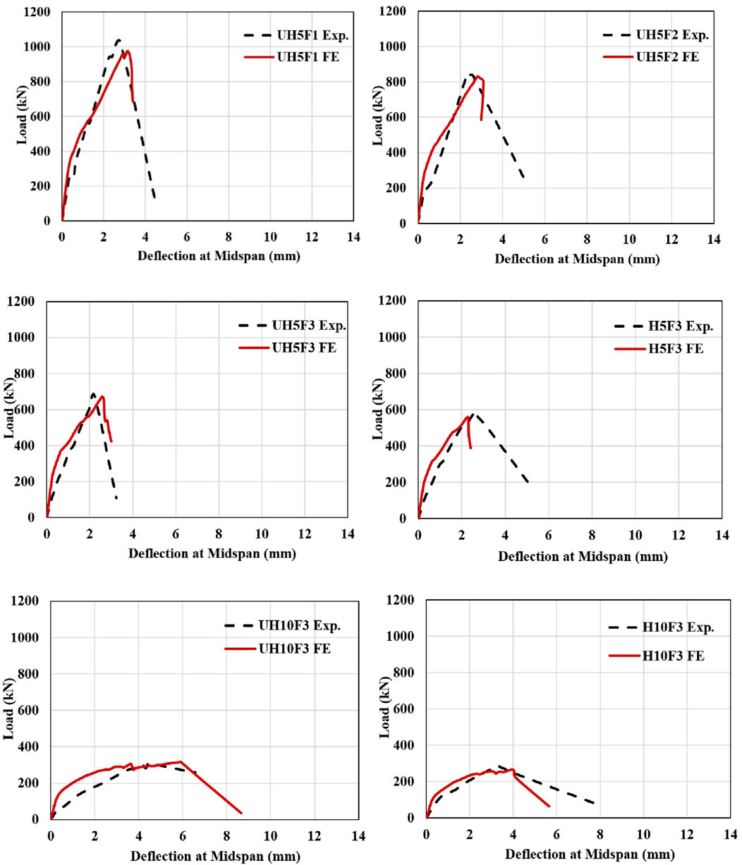
Figure 4. Comparison of load-deflection curves.
3.2 Unstrengthened behaviour
The validated FE model provided insight into the structural behaviour of deep beams with existing web openings and without shear links. The effects of concrete strength, a/d ratio, web opening dimensions, and the location of the web opening, all of which significantly influenced the behaviour, were investigated.
3.2.1 Concrete strength and a/d ratio
The impression of concrete strength on the unstrengthened behaviour was investigated through a parametric analysis of specimens identical to UH5F3 and UH10F3. Thus, the influence of concrete strength was examined for both a/d ratios of 0.54 and 1.08. All properties of the specimens including boundary conditions, geometrical details such as cross-sectional dimensions, the position of web openings, and their dimensions were kept identical. The impact of concrete strength was investigated. This was done by considering different concrete compressive strengths of 40, 60, 80, and 100 MPa for both beam series with a/d ratios of 0.54 and 1.08. The variation in shear force capacity with respect to concrete compressive strength is illustrated in Figure 5a. As shown in the figure, an increase in the a/d ratio from 0.54 to 1.08 caused a reduction in the shear force capacity. For example, the shear force capacity diminished from 238.7 kN to 125.6 kN as the a/d ratio increased from 0.54 to 1.08 for beams with a compressive strength of 40 MPa. In addition, shear force capacity increased with increasing concrete compressive strength for both beam series. An increase in compressive strength from 40 MPa to 100 MPa instigated a rise in shear force capacity from 238.7 kN to 347.2 kN (by approximately 45.5%) for beams with an a/d ratio of 0.54, and from 125.6 kN to 165.8 kN (by approximately 32%) for beams with an a/d ratio of 1.08. However, the rate of increase was more gradual in beams with an a/d ratio of 1.08 compared to those with an a/d of 0.54. This behaviour can be attributed to the reduced effectiveness of arch action at higher a/d ratios, where the load path becomes longer. This leads to a reduction in the efficiency of direct compression through which the applied load is transferred. Beams with higher a/d ratios are therefore subjected to more truss action, which is less effective in providing shear resistance. To provide more depth in understanding the effect of the a/d ratio, FE analyses were also conducted on specimens identical to UH10F3 but had different a/d ratios ranging from 1.08 to 2.7. All parameters were kept constant except for the shear span. The numerically tested beams had shear spans of 600, 900, 1200, and 1500 mm corresponding to a/d ratios of 1.08, 1.62, 2.16, and 2.7, respectively. Figure 5b shows the effect of the a/d ratio on the shear force capacity. An increase in the a/d ratio from 1.08 to 2.7 instigated a reduction in the shear force capacity from 151 to 75 kN (by about 50%).
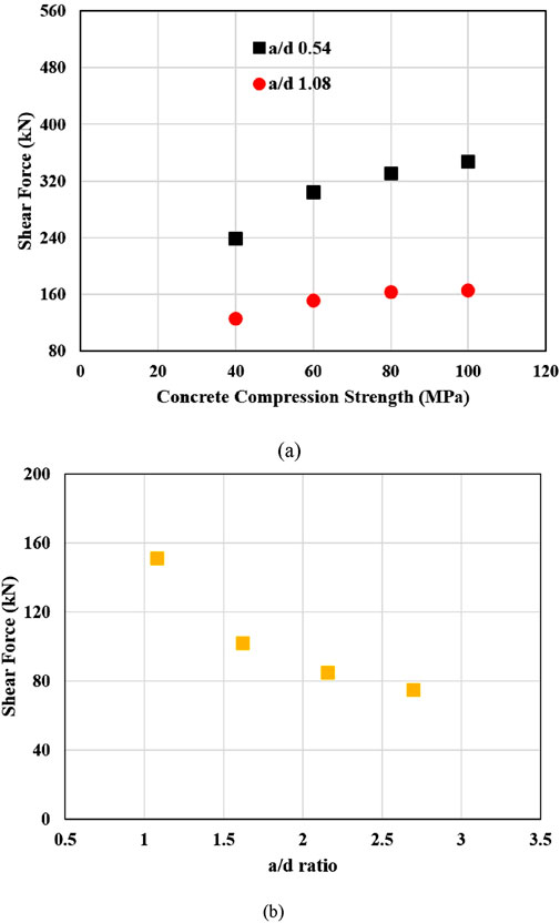
Figure 5. Effects of concrete compression strength and a/d ratio; (a) concrete compression strength (b) a/d ratio.
3.2.2 Web opening dimensions
The effect of web opening dimensions on the unstrengthened behaviour was investigated by conducting numerical analyses on beams identical to UH5F3. All the beams considered had the same material and geometrical properties but varied in web opening depth and width. Figure 6 depicts the relation between shear force and the ratio of web opening area (woa), calculated as x multiplied by y, to shear span area (ssa), calculated as (h × a) minus woa. As shown in the figure, the relation between shear force capacity and woa to ssa ratio is inverse. The shear force capacity significantly decreased as the woa/ssa ratio increased. A decrease in the woa/ssa ratio from 0.05 to 0.33 resulted in a significant reduction in shear force capacity, from 487.5 kN to 184.8 kN, a decrease of 62.1%. This trend indicated that larger web openings relative to the shear span adversely affected the shear resistance. The initial reduction in shear force capacity was steeper up to a woa/ssa ratio of 0.33, after which the reduction became more gradual. The effective shear-resisting area of the web of the beam was significantly reduced once the woa/ssa ratio exceeded 0.33; stress redistribution hence approached a near-steady state. Further increase in web opening diminished the load transfer to the support through direct compression. Consequently, as web openings become larger, the load transfer to the support through direct compression is increasingly disrupted in RC deep beams.
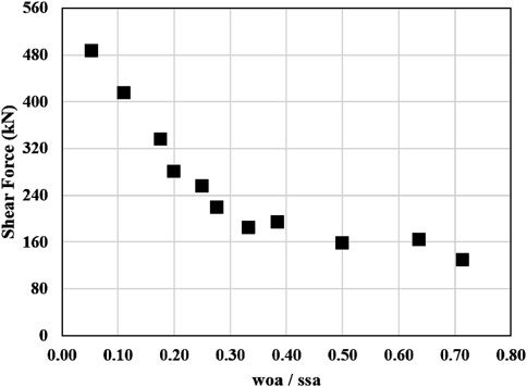
Figure 6. Effect of web opening dimensions.
3.2.3 Location of web opening
The location of the web opening was investigated by considering both the horizontal distance from the support and the vertical distance from the bottom of the beam. The beams were identical to UH5F3 and UH10F3; however, different horizontal distances from the support were numerically tested to evaluate the effect of horizontal distance. The horizontal distance was defined by factor c (see Figure 7) and varied as 0.25 and 0.75 times the shear span of either 300 or 600 mm. Accordingly, the corresponding centre-to-centre (c/c) distances were either 75 and 225 mm, or 150 or 450 mm. The vertical distance from the web opening to either the top or bottom of the beam was kept constant at 300 mm c/c, as illustrated in Figure 7. Similar to the investigation of horizontal distance, the effect of vertical distance was examined using beams identical to UH5F3 and UH10F3, but with varying vertical distances from the bottom of the beam. The vertical distance was defined by the factor d (see Figure 8) and varied as 0.25, and 0.75 times the total height of 600 mm. Thus, the corresponding c/c distances were 150 mm and 450 mm. The horizontal distance from the web opening to either the support or the loading point was kept constant at either 150- or 300-mm c/c, as illustrated in Figure 8.
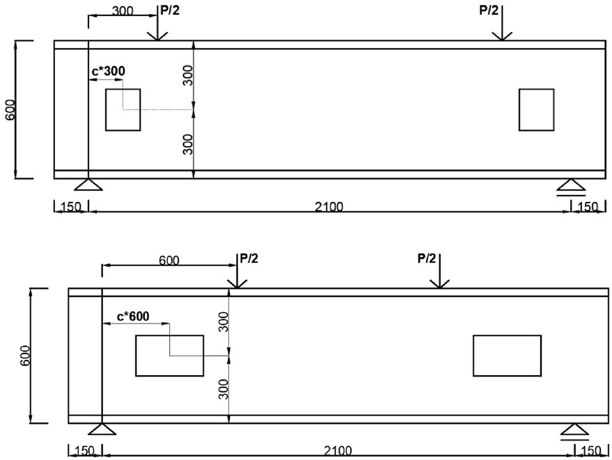
Figure 7. Effect of horizontal distance (all dimensions in mm).
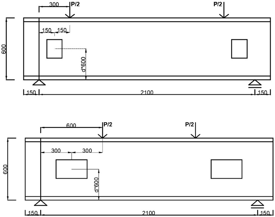
Figure 8. Effect of vertical distance (all dimensions in mm).
Figure 9 illustrates the effects of the vertical and horizontal distances of the web opening on the shear force capacity. The investigations were conducted by considering two a/d ratios of 0.54 and 1.08. Variations in the horizontal distance from the support influenced shear resistance for both series. For instance, increasing the distance from 75 to 225 mm (c/c) resulted in approximately a 15.8% increase in the shear force capacity of the beams (from 373.2 to 432.3 kN) with an a/d ratio of 0.54 (see Figure 9a). A similar trend was also obtained for beams with an a/d ratio of 1.08. The shear force capacity increased from 141.5 to 209.9 kN (by about 48%) with increasing distance from 150 to 450 mm c/c. These results confirmed that shear resistance increased as the horizontal distance from support increased. Figure 9b shows the variations in shear force capacity with respect to the vertical distance from the bottom face of the beams with a/d ratios of 0.54 and 1.08. An increase in the vertical distance from 150 mm to 450 mm caused a rise of about 15.5% in the shear force capacity of the beams (from 339.2 kN to 391.7 kN) with a/d ratios of 0.54 (see Figure 9b). The vertical distance from the bottom face of the beams with a/d ratios of 1.08 also had a similar trend. Shear force capacity increased from 119.6 to 264.6 kN with increasing vertical distance from the bottom face of the beam. These results showed that the shear force capacity increased as the web opening moved farther away from the bottom face of the beam. As a result, the shear force capacity of the beam is directly influenced by the extent to which arch action is interrupted in the direct load transfer to the support. Variations in shear resistance depend on the position of the web opening, which affects the continuity of the load path from the load point to the support.
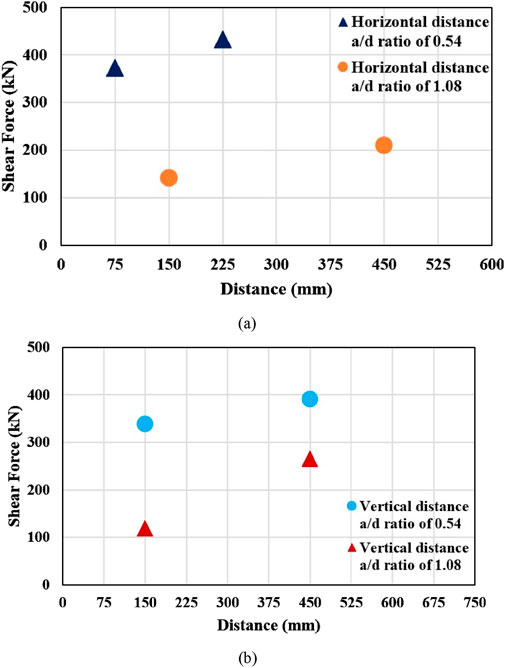
Figure 9. Location of web opening (a) Horizontal distance (b) Vertical distance.
3.3 Strengthened behaviour
The strengthening procedure was conducted by embedding CFRP bars into the shear spans. The CFRP bars used in following parametric studies had an elastic modulus of 130 GPa, a tensile strength of 2300 MPa, and an ultimate strain of 1.77%.
3.3.1 Shear resistance
The numerical analyses were conducted on beams identical to H5F3 and H10F3 but strengthened with embedded 12 mm CFRP bars. Two FRP bars were used, one placed near the support and the other near the loading point, as shown in Figure 10. All other parameters were kept constant to focus on investigating the effectiveness of the strengthening.
Figure 10. FE model of strengthened beam.
Figure 11 shows the variation in shear force versus midspan deflection for both unstrengthened and strengthened beams. The use of CFRP bars improved the shear force capacity in both series. For H5F3, the shear resistance increased by about 9.3% (from 278.6 to 304.4 kN) due to the embedded CFRP bars. In the case of H10F3, the CFRP bars improved the shear force capacity by about 33.8% (from 133.4 to 178.4 kN). The smaller rise in the shear resistance of H5F3 can be attributed to its lower a/d ratio of 0.54. As the a/d ratio decreases, arch action becomes more dominant, which means that the shear resistance is primarily carried by the concrete rather than the FRP bars. As shown in the figure, both unstrengthened and strengthened beams with an a/d ratio of 0.54 exhibited higher post-cracking stiffness compared to those with an a/d ratio of 1.08. This can be attributed that an increase in the a/d ratio leads to higher bending moments, resulting in more cracking and thus lower stiffness. Moreover, Figure 11 clearly indicates the presence of CFRP bars enhanced the post-cracking stiffness of the strengthened beams in comparison to their unstrengthened counterparts.
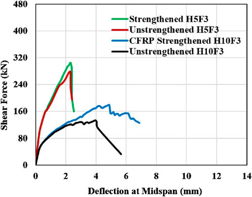
Figure 11. Shear force vs deflection at midspan.
3.3.2 FRP bar diameter and configuration
The effect of FRP bar diameter was examined by considering different CFRP bar diameters of 8, 10, and 12 mm. The numerically tested beams were identical to the CFRP-strengthened H10F3 and H5F3, and all parameters except for the bar diameter were kept constant. The shear capacities of the strengthened beams (Vt), together with the corresponding shear capacities of the unstrengthened beams (Vc), are given in Table 3. The FRP bar contribution (Vf), calculated as Vt minus Vc, is also included in the table. The total shear force capacity of the strengthened beams with a/d ratios of 0.54 and 1.08 increased from 291.5 to 304.4 kN (by approximately 4.4%) and from 162.7 to 178.4 kN (by approximately 9.6%), respectively, as the bar diameter increased from 8 to 12 mm. The FRP contribution also increased, respectively, from 12.9 to 25.8 kN and from 29.3 to 45 kN. The use of larger-diameter FRP bars can therefore enhance shear resistance by limiting crack opening. Figure 12 illustrates the variation of FRP bar diameter versus Vf (%) for beam series with a/d ratios of 0.54 and 1.08. As shown in the figure, Vf (%) gradually increased with increasing bar diameter from 8 to 12 mm. This gradual increase can be attributed to the dominant arch action, which is more significant than truss action in deep beams. This effect is clearly evident in Figure 12, as the strengthened beams with an a/d ratio of 0.54 exhibited lower Vf (%) values.
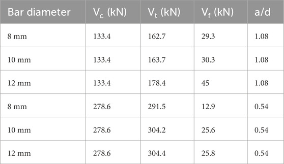
Table 3. Results on FRP bar diameter.
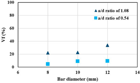
Figure 12. Effect of FRP bar diameter.
The effect of FRP bar configuration was investigated by varying the number and placement of CFRP bars in the shear span, positioned before and after the web openings, as shown in Figure 13. The numerically tested beams were identical to the CFRP-strengthened H10F3, but with varying numbers of CFRP bars in the shear span. The configurations are presented in Figure 13. In the first configuration, two CFRP bars were used—one placed before and the other after the web opening. The second configuration included a total of four CFRP bars, arranged in two pairs with a c/c spacing of 50 mm. The third configuration (Configuration C in Figure 13) also had four CFRP bars, but each pair was spaced at 75 mm c/c. Figure 14 shows the effect of these configurations. The CFRP bars significantly increased the shear force capacity in all cases. The ultimate shear capacities were comparable since the shear force capacity was primarily governed by arch action rather than truss action. The contribution of CFRP reinforcement increased from 45 to 51.6 kN (about by 14.7%). The shear force capacity of the beam with a web opening was significantly reduced when the load transfer to the support was interrupted by the opening. Therefore, the CFRP bar configuration should be designed with consideration of this effect.
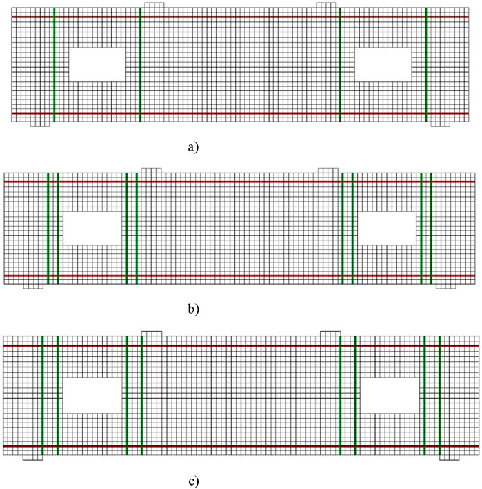
Figure 13. Different configurations of embedded CFRP bars (a) Configuration A, (b) Configuration B, (c) Configuration C.

Figure 14. Effect of CFRP bar configuration.
4 Comparison of design model predictions
TR55 (2012) is presently the only official standard that addresses the design of embedded FRP systems. TR55 (2012) employs the truss analogy to predict FRP contribution which is given by Equation 8.
where Ɛfse is the effective strain, which can be taken as 0.004; Ef is the elastic modulus of the FRP bar; and Weff is the effective width, calculated as given in Equation 9.
where h is the strengthening depth and lb,max, the maximum anchorage length, is calculated using Equation 10.
where db is the bar diameter, τb, the average bond stress, can be taken as 15 MPa, ƔA, the safety factor for adhesive material, can be taken as one for fair comparison.
The properties of the numerically tested beams are listed in Table 4. The FE model–predicted Vf values, along with the corresponding TR55 (2012) predictions, are presented in Table 5. The TR55 design code (2012) significantly overestimated the contribution of CFRP bars, with a mean value of 2.57. This can be attributed to the fact that TR55 (2012), based on the truss analogy, provides accurate predictions primarily for slender beams. Arch action, where the applied load is transferred to the support through direct compression, is dominant in deep beams compared to truss action. Therefore, TR55 (2012) overestimated the strengthened shear force capacity. The purpose of this comparison is to highlight the need for a specific design formulation for deep beams strengthened with embedded FRP bars. Further experimental research is necessary to investigate the behaviour of both unstrengthened and DE-strengthened beams with existing openings. The development of an accurate design model has been identified as a crucial focus for future work, supported by experimental study and additional parametric finite element research.
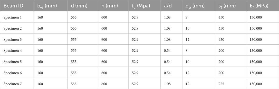
Table 4. Properties of the numerically tested beams.
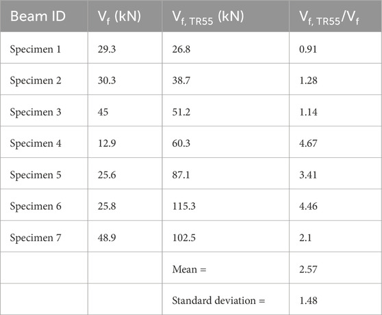
Table 5. Comparison of TR55 predictions.
5 Conclusion
This study aimed to investigate the behaviour of high-strength concrete deep beams with web openings, taking into account both the unstrengthened condition, which has not yet been fully understood, and the strengthened condition with embedded CFRP bars, which has not been studied yet. The outcomes of this study allow for the following main conclusions to be drawn.
• The developed FE model gave accurate prediction for the ultimate load capacities. This was proved with a standard deviation of 0.03 and a mean value of 0.97. These findings are noteworthy because they show that the FE model can be a trustworthy predictive tool for the practical design of concrete deep beams with web opening.
• The effect of concrete strength was examined for unstrengthened beams with a/d ratios of 0.54 and 1.08. Increasing the concrete strength from 40 to 100 MPa instigated an improvement in shear force capacity of approximately 45.5% and 32%, respectively. The effect of the a/d ratio on shear force capacity was also examined separately. An increase in the a/d ratio from 1.08 to 2.7 resulted in a reduction in shear force capacity by approximately 50%.
• The effect of web opening dimensions was investigated by taking into account the ratio of web opening area to shear span area. An inverse relationship was observed between shear force capacity and this ratio. When the ratio increased from 0.05 to 0.33, the shear force capacity decreased by 62.1%. This indicates that larger web openings relative to the shear span significantly decrease shear resistance. Beyond a ratio of 0.33, the rate of reduction in shear resistance became more gradual. The effective shear-resisting area of the web of the beam was significantly reduced once the woa/ssa ratio exceeded 0.33; stress redistribution hence approached a near-steady state. Further increase in web opening diminished the load transfer to the support through direct compression. Consequently, as web openings become larger, the load transfer to the support through direct compression is increasingly disrupted in RC deep beams.
• An increase in the horizontal distance from the support and the vertical distance from the bottom of the beam instigated an increase in shear resistance for beams with a/d ratios of 0.54 and 1.08. Shear resistance was directly affected by the position of the web opening. The position of web opening affected the continuity of the load path from the loading point to the support.
• The use of CFRP bars enhanced the shear force capacity of the beams. Shear resistance increased by approximately up to 33.8%. With increasing the CFRP bar diameter from 8 mm to 12 mm, the contribution to shear resistance also increased. The use of larger-diameter FRP bars can enhance shear resistance by limiting crack opening. In addition, the shear resistance was affected by the configuration of the CFRP bars. The shear resistance of beams with web openings was significantly reduced when load transfer to the support was interrupted by the opening. The CFRP bar configuration should therefore be designed to account for this effect.
• The TR55 design code significantly overestimated the contribution of CFRP bars. The purpose of this comparison is to highlight the need for a specific design formulation for DE FRP- strengthened deep beams strengthened with existing web openings. Further experimental research is necessary to investigate the behaviour of both unstrengthened and DE-strengthened beams with existing openings.
Data availability statement
The original contributions presented in the study are included in the article/supplementary material, further inquiries can be directed to the corresponding author.
Author contributions
KS: Investigation, Software, Writing – review and editing, Conceptualization, Validation, Formal Analysis, Writing – original draft, Methodology, Visualization. BE: Formal Analysis, Writing – review and editing.
Funding
The author(s) declare that no financial support was received for the research and/or publication of this article.
Conflict of interest
The authors declare that the research was conducted in the absence of any commercial or financial relationships that could be construed as a potential conflict of interest.
Generative AI statement
The author(s) declare that no Generative AI was used in the creation of this manuscript.
Any alternative text (alt text) provided alongside figures in this article has been generated by Frontiers with the support of artificial intelligence and reasonable efforts have been made to ensure accuracy, including review by the authors wherever possible. If you identify any issues, please contact us.
Publisher’s note
All claims expressed in this article are solely those of the authors and do not necessarily represent those of their affiliated organizations, or those of the publisher, the editors and the reviewers. Any product that may be evaluated in this article, or claim that may be made by its manufacturer, is not guaranteed or endorsed by the publisher.
References
Abdul-Razzaq, K. S., Ali, H. I., and Abdul-Kareem, M. M. (2017). A new strengthening technique for deep beam openings using steel plates. Int. J. Appl. Eng. Res. 12 (24), 15935–15947. Available online at: https://www.ripublication.com/ijaer17/ijaerv12n24_268.pdf, https://www.ripublication.com/Volume/ijaerv12n24.htm.
Alsaeq, H. M. (2013). Effects of opening shape and location on the structural strength of RC deep beams with openings. World Acad. Sci. Eng. Technol. Int. J. Civ. Environ. Eng. 7 (6), 494–499. doi:10.5281/zenodo.1329204
Bui, L. V. H., Stitmannaithum, B., and Ueda, T. (2020). Experimental investigation of concrete beams strengthened with embedded through-section steel and FRP bars. ASCE J. Compos. Constr. 24 (5), 04020052. doi:10.1061/(ASCE)CC.1943-5614.0001055
Campione, G., and Minafo, G. (2012). Behaviour of concrete deep beams with openings and low shear span-to-depth ratio. Eng. Struct. 41, 294–306. doi:10.1016/j.engstruct.2012.03.055
Caro, M., Dirar, S., Quinn, A., and Yapa, H. (2023). Shear strengthening of existing reinforced concrete beams with embedded bars – an overview. Proc. Institution Civ. Eng. - Struct. Build. 176, 439–452. doi:10.1680/jstbu.20.00169
Chaallal, O., Mofidi, A., Benmokrane, B., and Neale, K. (2011). Embedded through-section FRP rod method for shear strengthening of RC beams: performance and comparison with existing techniques. ASCE J. Compos. Constr. 15 (3), 374–383. doi:10.1061/(asce)cc.1943-5614.0000174
Chin, S. C., Shafiq, N., Kusbiantoro, A., and Nuruddin, M. F. (2014). Reinforced concrete deep beams with openings strengthened using FRP – a review. Adv. Mater. Res. 1025–1026, 938–943. doi:10.4028/www.scientific.net/amr.1025-1026.938
De Lorenzis, L., and Nanni, A. (2001). Shear strengthening of reinforced concrete beams with near-surface mounted fiber-reinforced polymer rods. ACI Struct. J. 98 (1), 60–68. doi:10.14359/10147
Dirar, S., Caro, M., Sogut, K., and Quinn, A. (2024). Experimental behaviour, FE modelling and design of large-scale reinforced concrete deep beams shear-strengthened with embedded fibre reinforced polymer bars. Structures 67, 106938. doi:10.1016/j.istruc.2024.106938
Dirar, S., Sogut, K., Caro, M., Rahman, R., Theofanous, M., and Faramarzi, A. (2025). Effect of shear span-to-effective depth ratio and FRP material type on the behaviour of RC T-beams strengthened in shear with embedded FRP bars. Eng. Struct. 332, 120105. doi:10.1016/j.engstruct.2025.120105
Dutta, B., Kumari, A., and Nayak, A. N. (2022). Shear behaviour of RC deep beams retrofitted with externally bonded GFRP fabrics: experimental and numerical study. Structures 46, 1–16. doi:10.1016/j.istruc.2022.10.042
Dutta, B., Nayak, A. N., Dirar, S., Nanda, B., and Theofanous, M. (2023). Shear strengthening of continuous RC T-beams with deep embedded CFRP and steel bars: a numerical study. Structures 52, 187–204. doi:10.1016/j.istruc.2023.03.157
El Maaddawy, T., and Sherif, S. (2009). FRP composites for shear strengthening of reinforced concrete deep beams with openings. Compos. Struct. 89 (1), 60–69. doi:10.1016/j.compstruct.2008.06.022
Erfan, A. M., Hafez, R., and Badawy, M. M. (2024). Behavior of high strength concrete deep beams reinforced with basalt fiber reinforced polymer bars with and without openings. Structures 69, 107397. doi:10.1016/j.istruc.2024.107397
Fawzy, A., EL-Helloty, A., Mahmoud, M. H., and Summra, A. (2024). Investigating reinforced concrete beams with web opening under static and cyclic loads. J. Eng. 2024, 3511913. doi:10.1155/2024/3511913
Godat, A., Chaallal, O., and Neale, K. W. (2013). Nonlinear finite element models for the embedded through-section FRP shear-strengthening method. Comput. and Struct. 119, 12–22. doi:10.1016/j.compstruc.2012.12.016
Gong, B., and Li, H. (2024). A couple voronoi-RBSM modeling strategy for RC structures. Struct. Eng. Mech. 91 (3), 239–250. doi:10.12989/sem.2024.91.3.239
Guan, H., and Doh, J. H. (2007). Development of strut-and-tie models in deep beams with web openings. Adv. Struct. Eng. 10 (6), 697–711. doi:10.1260/136943307783571427
Hassan, H. M., Arab, M. A. E. S., and El-Kassas, A. I. (2019). Behavior of high strength self compacted concrete deep beams with web openings. Heliyon 5 (4), e01524. doi:10.1016/j.heliyon.2019.e01524
Hu, O. E., and Tan, K. H. (2007). Large reinforced-concrete deep beams with web openings: test and strut-and-tie results. Mag. Concr. Res. 59 (6), 423–434. doi:10.1680/macr.2007.59.6.423
Ibrahim, M. A., El Thakeb, A., Mostfa, A. A., and Kottb, H. A. (2018). Proposed formula for design of deep beams with shear openings. HBRC J. 14 (3), 450–465. doi:10.1016/j.hbrcj.2018.06.001
Ibrahim, N., Elkholy, S., Godat, A., and El-Kholy, A. (2023). Implementation of modified compression field theory to simulate the behavior of fiber-reinforced polymer shear-strengthened reinforced concrete beams under monotonic loading. Buildings 13, 898. doi:10.3390/buildings13040898
Ismail, E., Issa, M. S., and Elbadry, K. (2021). Finite element analysis of reinforced concrete deep beam with large opening. Beni-Suef Univ. J. Basic Appl. Sci. 10, 25. doi:10.1186/s43088-021-00104-z
Jasim, W. A., Allawi, A. A., and Oukaili, N. K. (2018). Strength and serviceability of reinforced concrete deep beams with large web openings created in shear spans. Civ. Eng. J. 4 (11), 2560–2574. doi:10.28991/cej-03091181
Jiang, H., Chen, Z., Fang, Z., Fang, S., Tu, W., Mo, F., et al. (2025). Rapid hardening high performance concrete (RHHPC) for bridge expansion joints: from material properties to interfacial shear performance. Constr. Build. Mater. 458, 139638. doi:10.1016/j.conbuildmat.2024.139638
Kani, G. N. J. (1964). The riddle of shear failure and its solution. ACI J. Proc. 61 (4), 441–468. doi:10.14359/7791
Kani, G. N. J. (1967). How safe are our large reinforced concrete beams? ACI J. Proc. 64 (3), 128–141. doi:10.14359/7549
Khalil, A. H. A., Etman, E. E., and El-Nasr, A. E. A. (2004). Behavior of high strength concrete deep beams with openings. Ain Shams Eng. J. 39 (3), 123–140. Available online at: https://scholar.google.com/scholar?q=Khalil%20A-HA%2C%20Etman%20EE%2C%20EL-Nasr%20AEA.%20Behavior%20of%20high%20strength%20concrete%20deep%20beams%20with%20openings.
Liu, J., and Mihaylov, B. (2020). Shear strength of RC deep beams with web openings based on two-parameter kinematic theory. Struct. Concr. 21 (1), 349–361. doi:10.1002/suco.201800356
Liu, F., Tang, R., Li, Q., Wang, H., Zou, Y., and Yuan, X. (2025). Improved thermal performance, frost resistance, and pore structure of cement–based composites by binary modification with mPCMs/nano–SiO2. Energy 332, 137166. doi:10.1016/j.energy.2025.137166
Lu, W. Y., Lin, G. Z., Tseng, C. C., and Lin, S. J. (2020). Shear strength of reinforced concrete deep beams with web openings. J. Chin. Inst. Eng. 43 (7), 694–705. doi:10.1080/02533839.2020.1796816
Luo, J., Wu, G., Zhao, G., Ma, Y., Fang, Z., and Fang, S. (2025). Experimental and numerical analysis on shear performance of single embedded nut bolted shear connectors in prefabricated steel-UHPC composite structures under cyclic loading. Structures 73, 108446. doi:10.1016/j.istruc.2025.108446
Maaddawy, T., and El-Ariss, B. (2012). Behavior of concrete beams with shortshear span and web opening strengthened in shear with CFRP composites. J. Compos. Constr. 16 (1), 47–59. doi:10.1061/(asce)cc.1943-5614.0000237
Mabrouk, R. T. S., Mahmoud, M. A. S., and Kassem, M. E. (2022). Behavior of reinforced concrete deep beams with openings under vertical loads using strut and tie model. Civ. Eng. J. 7, 148–170. doi:10.28991/cej-sp2021-07-011
Mofidi, A., Chaallal, O., Benmokrane, B., and Neale, K. (2012). Experimental tests and design model for RC beams strengthened in shear using the embedded through-section FRP method. ASCE J. Compos. Constr. 16 (5), 540–550. doi:10.1061/(asce)cc.1943-5614.0000292
Mohamed, A. R., Shoukry, M. S., and Saeed, J. M. (2014). Prediction of the behavior of reinforced concrete deep beams with web openings using the finite element method. Alexandria Eng. J. 53 (2), 329–339. doi:10.1016/j.aej.2014.03.001
Muhammad, J. H. (2025). Effect of basalt macro fiber on shear strength of high-strength concrete beams with web openings: a finite element parametric study. Case Stud. Constr. Mater. 23, e05088. doi:10.1016/j.cscm.2025.e05088
Nie, X. F., Zhang, G. M., Chen, T. Y., and Yu, T. (2020). Strengthening of RC beams with rectangular web openings using externally bonded FRP: numerical simulation. Compos. Struct. 248, 112552. doi:10.1016/j.compstruct.2020.112552
Palermo, D., and Vecchio, F. J. (2007). Simulation of cyclically loaded concrete structures based on the finite-element method. J. Struct. Eng. 133, 728–738. doi:10.1061/(asce)0733-9445(2007)133:5(728)
Qapo, M., Dirar, S., and Jemaa, Y. (2016). Finite element parametric study of reinforced concrete beams shear-strengthened with embedded FRP bars. Compos. Struct. 149, 93–105. doi:10.1016/j.compstruct.2016.04.017
Saleh, M., AlHamaydeh, M., and Zakaria, M. (2023). Finite element analysis of reinforced concrete deep beams with square web openings using damage plasticity model. Eng. Struct. 278, 115496. doi:10.1016/j.engstruct.2022.115496
Shabanlou, M., Meghdadi, Z., and Ghaffar, S. H. (2025). Experimental and analytical study of the residual performance of reinforced concrete deep beams with circular web openings. Results Eng. 25, 104229. doi:10.1016/j.rineng.2025.104229
Shi, T., Li, K., Wang, C., Jin, Z., Hao, X., Sun, P., et al. (2025). Fracture toughness of recycled carbon fibers reinforced cement mortar and its environmental impact assessment. Case Stud. Constr. Mater. 22, e04866. doi:10.1016/j.cscm.2025.e04866
Sogut, K. (2025). Structural behaviour of concrete deep beams reinforced with aluminium alloy bars. Appl. Sci. 15, 5453. doi:10.3390/app15105453
Sogut, K., Dirar, S., Theofanous, M., Faramarzi, A., and Nayak, A. N. (2021). Effect of transverse and longitudinal reinforcement ratios on the behaviour of RC T-beams shear strengthened with embedded FRP BARS. Compos. Struct. 262, 113622. doi:10.1016/j.compstruct.2021.113622
Sogut, H., Ozcelik, R., Sogut, K., and Erdal, F. (2025). Experimental behavior and FE modeling of buckling restrained braced frame with slip-critical connection. Appl. Sci. 15 (10), 5626. doi:10.3390/app15105626
Teng, J. G., Chen, J. F., Smith, S. T., and Lam, L. (2003). Behaviour and strength of FRP strengthened RC structures: a state-of-the-art review. Proc. Institution Civ. Eng. - Struct. Build. 156 (1), 51–62. doi:10.1680/stbu.156.1.51.37880
The Concrete Society (2012). Technical report no. 55 design guidance for strengthening concrete structures using fibre composite materials. third ed. Crowthorne: The Concrete Society.
Thorenfeldt, E., Tomaszewicz, A., and Jensen, J. J. (1987). “Mechanical properties of high strength concrete and applications in design,” in Utilization of HighStrength concrete. Stavanger: Tapir, 149–159.
Triantafillou, T. C. (1998). Shear strengthening of reinforced concrete beams using epoxy bonded FRP composites. ACI Struct. J. 95 (2), 107–115. doi:10.14359/531
Valerio, P., and Ibell, T. J. (2003). Shear strengthening of existing concrete bridges. Proc. Institution Civ. Eng. Struct. Build. 156 (1), 75–84. doi:10.1680/stbu.156.1.75.37881
Valerio, P., Ibell, T. J., and Darby, A. P. (2009). Deep embedment of FRP for concrete shear strengthening. Proc. Institution Civ. Eng. Struct. Build. 162 (5), 311–321. doi:10.1680/stbu.2009.162.5.311
Vecchio, F. J. (2000). Disturbed stress field model for reinforced concrete: formulation. ASCE J. Struct. Eng. 126 (9), 1070–1077. doi:10.1061/(asce)0733-9445(2000)126:9(1070)
Vecchio, F. J., and Collins, M. P. (1986). The modified compression field theory for reinforced concrete elements subjected to shear. ACI Struct. J. 83 (2), 219–231. doi:10.14359/10416
Vecchio, F. J., and Collins, M. P. (1993). Compression response of cracked reinforced concrete. ASCE J. Struct. Eng. 119 (12), 3590–3610. doi:10.1061/(asce)0733-9445(1993)119:12(3590)
Wong, P. S., Vecchio, F. J., and Trommels, H. (2013). VecTor2 and FormWorks user’s manual second edition. Toronto: University of Toronto.
Wu, H. C., and Eamon, C. D. (2017). Strengthening of concrete structures using fiber reinforced polymers (FRP): Design, construction and practical applications. UK: Woodhead Publishing.
Yang, K. H., Eun, H. C., Lee, E. T., and Chung, H. S. (2003). Shear characteristics of high-strength concrete deep beams without shear reinforcements. Eng. Struct. 25 (8), 1343–1352. doi:10.1016/s0141-0296(03)00110-x
Yang, K. H., Eun, H. C., and Chung, H. S. (2006). The influence of web openings on the structural behavior of reinforced high-strength concrete deep beams. Eng. Struct. 28 (13), 1825–1834. doi:10.1016/j.engstruct.2006.03.021
Yang, L., Gao, Y., Chen, H., Jiao, H., Dong, M., Bier, T. A., et al. (2024). Three-dimensional concrete printing technology from a rheology perspective: a review. Adv. Cem. Res. 36 (12), 567–586. doi:10.1680/jadcr.23.00205
Yang, C., Nan, Z., Huo, Y., Yang, Y., Xu, P., Xiao, Y., et al. (2025). Design, characterisation, and crushing performance of hexagonal-quadrilateral lattice-filled steel/CFRP hybrid structures. Compos. Part B Eng. 304, 112631. doi:10.1016/j.compositesb.2025.112631
Yoo, T. M., Doh, J. H., Guan, H., and Fragomeni, S. (2013). Experimental behaviour of high-strength concrete deep beams with web openings. Struct. Des. Tall Special Build. 22, 655–676. doi:10.1002/tal.718
Keywords: CFRP, concrete, deep beam, FRP material, finite element, strengthening, web opening
Citation: Sogut K and Ercan B (2025) Behaviour of unstrengthened and DE CFRP-strengthened high-strength concrete deep beams with web openings. Front. Mater. 12:1661180. doi: 10.3389/fmats.2025.1661180
Received: 07 July 2025; Accepted: 09 September 2025;
Published: 22 September 2025.
Edited by:
Annalisa Napoli, University of Salerno, ItalyReviewed by:
Mahmoud Ebrahimi, University of Maragheh, IranZhuangcheng Fang, Guangdong University of Technology, China
Copyright © 2025 Sogut and Ercan. This is an open-access article distributed under the terms of the Creative Commons Attribution License (CC BY). The use, distribution or reproduction in other forums is permitted, provided the original author(s) and the copyright owner(s) are credited and that the original publication in this journal is cited, in accordance with accepted academic practice. No use, distribution or reproduction is permitted which does not comply with these terms.
*Correspondence: Kagan Sogut, a2FnYW4uc29ndXRAa2lsaXMuZWR1LnRy