Abstract
Prefabricated bridges have emerged as a significant trend in modern bridge construction. To study the in-plane and out-of-plane flexural performance of ultra-high-performance concrete (UHPC) beams with wet joints, in-plane and out-of-plane specimens with different curing methods for UHPC wet joints were designed and fabricated. The cracking loads, peak loads, and crack development of the specimens were recorded and analyzed. The test results revealed that all specimens experienced flexural failure with damage to the normal section. Moreover, the flexural capacity of the jointed specimens reached a minimum of 91% of the complete specimen’s flexural capacity. The joints influenced the cracking behavior of in-plane specimens but had minimal impact on out-of-plane specimens. Chiseling, increasing steel fiber contents and welding longitudinal steel bars with short steel bars reduced structural damage and decrease in stiffness. The different curing methods for UHPC at the joints have little impact on stiffness and flexural capacity of the joint specimens but played a positive role in improving ductility. Finally, a calculation method for flexural capacity considering the contribution of web steel bars is provided.
1 Introduction
Ultra-high performance concrete (UHPC), a novel type of cementitious material with precise performance specifications, exhibits exceptional characteristics such as high compressive strength (>150 MPa), significant tensile strength (>5 MPa), exceptional toughness, durability, and strain-hardening behavior (Wille et al., 2014; Haber et al., 2018). UHPC bridges are frequently prefabricated and assembled to ensure construction quality and expedite project timelines. However, prefabricated assembled UHPC bridge structures lack continuity in steel fiber distribution and longitudinal steel bars due to the different casting times (Li et al., 2018). Meanwhile, the mechanical and durability properties of these structures are crucial factors that influence their overall stress distribution and performance (Russell and Graybeal, 2013). Consequently, conducting comprehensive research on the joints of prefabricated assembled UHPC bridges holds significant importance.
In prefabricated UHPC bridges, the common joint type employed is typically a wet joint. Numerous studies have been conducted on the mechanical performance of wet joint. However, these studies have primarily focused on normal concrete (NC) joints and NC-UHPC joints and studies available on the mechanical performance of full-size UHPC wet joint structures is limited. Chapman (2010) conducted flexural experiments on plain concrete wet joint specimens with U-shaped steel bars. The results indicated that U-shaped steel bars can help reduce crack width at wet joints, and joint slabs reinforced with U-shaped steel bars outperformed those with straight steel bars. Arafa et al. (2016) carried out flexural experiments on plain concrete slab and beam specimens using different materials for joints. The experimental results showed that the NC-UHPC joint specimens performed better than the complete plain concrete specimens. The cracking performance of the UHPC wet joint specimens surpassed that of the complete plain concrete specimens. After observing good mechanical performance of NC-UHPC joint specimens, scholars began to pay attention to the effects of different joint designs and other experimental variables on the mechanical properties of NC-UHPC joint specimens. Peng and Yan (2020) conducted flexural experiments on one complete beam and five jointed beams with various joint types, including vertical joint, rhombus joint, vertical joint with top and bottom strips, tied rhombus joint with top and bottom strips, and welded rhombus joint with top and bottom strips. The results indicated that the welded rhombic joint with top and bottom strips exhibited the highest stiffness, strongest cracking resistance, and best flexural capacity. Feng et al. (2022) fabricated different types and shapes of UHPC wet jointed beams and conducted flexural experiments. The results revealed that the maximum crack width of UHPC wet jointed beams appeared at the interface between the joint and the prefabricated part. UHPC wet jointed beams with inverted trapezoidal joints exhibited better performance, and the flexural performance of UHPC jointed beams with top and bottom strip joints or rhombus joints was superior to that of rectangular ones. Zhang et al. (2020a), Zhu et al. (2021) proposed a prestressed bolt hybrid connection and studied its flexural capacity, characteristic load values, deformation characteristics, and damage modes. The effects of bolts and epoxy adhesive on the flexural capacity of the node are also discussed.
Steel fibers were noted to play a crucial role in the mechanical properties of UHPC. Jung et al. (2014) used retarder to slow down the strength development of UHPC at the joints and exposed steel fibers by breaking part of the concrete at the interface. The exposure of steel fibers ensured the ductility of the prefabricated UHPC bridge deck at the joints and reduced crack width. Qiu et al. (Zhao et al., 2022) proposed an innovative UHPC joint and conducted tensile tests to address the discontinuity of steel fibers at the joints. The fiber-fine parameters with similar tensile properties to monolithically cast specimens were obtained.Qiu et al. (2025) proposed a T-shaped steel plate-UHPC composite wet joint for prefabricated UHPC bridge decks. The experimental results indicate that composite joints are comparable to cast-in-place UHPC joints in terms of mechanical properties and have better ductility. Lu et al. (2025) proposed a novel steel plate-coarse aggregate UHPC composite joint to enhance the crack resistance of precast steel-UHPC composite beams under negative bending moment. The composite joints reached or even exceeded the level of cast-in-place joints in terms of load-bearing capacity, stiffness, and crack resistance. A prediction method for flexural bearing capacity considering the actual contribution of fibers was proposed.
The treatment of steel bars and the parameter details at the joint were also one of the key factors affecting the mechanical properties of wet joints. Yin et al. (2022) used ABAQUS to analyze the impact of reinforcement ratio on the mechanical properties of UHPC wet joints, discovering a “bimodal effect” of reinforcement ratio on tangential shear stress at the interface. A reinforcement ratio of 4.8% for wet joints was recommended. Qiu et al. (2022) conducted flexural experiments on 12 UHPC joint slabs and found that increasing the steel bar diameter not only enhanced the flexural capacity of UHPC joints but also improved crack resistance. The weak section of the wet joint specimen is typically found at the interface between the precast and the cast-in-place part. Jang and Lee (2017) set a 7-level treatment method for joint interfaces from the material’s point of view, which led to the derivation of a reasonable surface treatment method for joints. Qi et al. (2019), Lu et al. (2021) utilized steel wire mesh (SWM) to treat dovetail groove wet joints and conducted fatigue and flexural experiments. The findings indicated that SWM interface treatment effectively ensured fiber bridging at interfaces, significantly enhancing the mechanical properties of jointed UHPC panels and dispersing fatigue cracks.
In the experimental study mentioned above, the dimensions discussed mainly revolve around the material composition of UHPC, the joint form of the specimen, and the interface treatment. There is limited consideration given to whether UHPC wet joints require steam curing like prefabricated segments. Moreover, in actual use, for arch bridges (especially prefabricated ones), lightweight bridges such as pedestrian bridges, and some beam bridges with larger spans and smaller widths, earthquake and wind loads may cause out of plane deformation of the wet joints. However, the research mentioned above on the bending performance of UHPC wet joints has only focused on in-plane bending, neglecting the investigation of joint specimens under out-of-plane bending performance. Therefore, three in-plane specimens and three out-of-plane specimens were designed and fabricated. Subsequently, a flexural load experiment is conducted on these specimens. Through analysis of their cracking loads, ultimate loads, and crack development, a corresponding method for calculating flexural bearing capacity is proposed.
2 Experimental program
2.1 Design of specimens
To investigate the in-plane and out-of-plane flexural performance of UHPC rhombus wet joint specimens, a total of three UHPC test beams and three UHPC test plates are designed and fabricated as in-plane and out-of-plane flexural specimens. These will subsequently be referred to as in-plane and out-of-plane specimens. As depicted in Table 1, the in-plane specimens comprise one complete UHPC beam (I-1), one joint beam with UHPC steam-cured at the joint (I-2), and one joint beam with UHPC naturally cured at the joint (I-3). The out-of-plane specimens include one complete slab (O-1), one joint slab with UHPC steam-cured at the joint (O-2), and one joint slab with UHPC naturally cured at the joint (O-3). Specific details regarding the dimensions, reinforcement, and wet joints of the experimental specimens are shown in Figures 1, 2. It is worth noting that in order to enhance the load-bearing capacity of the interface and reduce the possibility of relative sliding of the interface, shear keys are set on both sides of the interface when designing the specimen to improve the shear resistance of the interface.
TABLE 1
| Name of specimens | Shape of joint connection | Ratio of longitudinal steel reinforcement/% | Ratio of stirrups reinforcement/% | UHPC wet joint maintenance method |
|---|---|---|---|---|
| I-1 | Complete beam | 0.45 | 0.71 | — |
| I-2 | Rhombus wet joint | 0.45 | 0.71 | Steam curing |
| I-3 | Rhombus wet joint | 0.45 | 0.71 | Natural curing |
| O-1 | Complete slab | 1.46 | 0.35 | — |
| O-2 | Rhombus wet joint | 1.46 | 0.35 | Steam curing |
| O-3 | Rhombus wet joint | 1.46 | 0.35 | Natural curing |
Main parameters of experimental specimens.
FIGURE 1
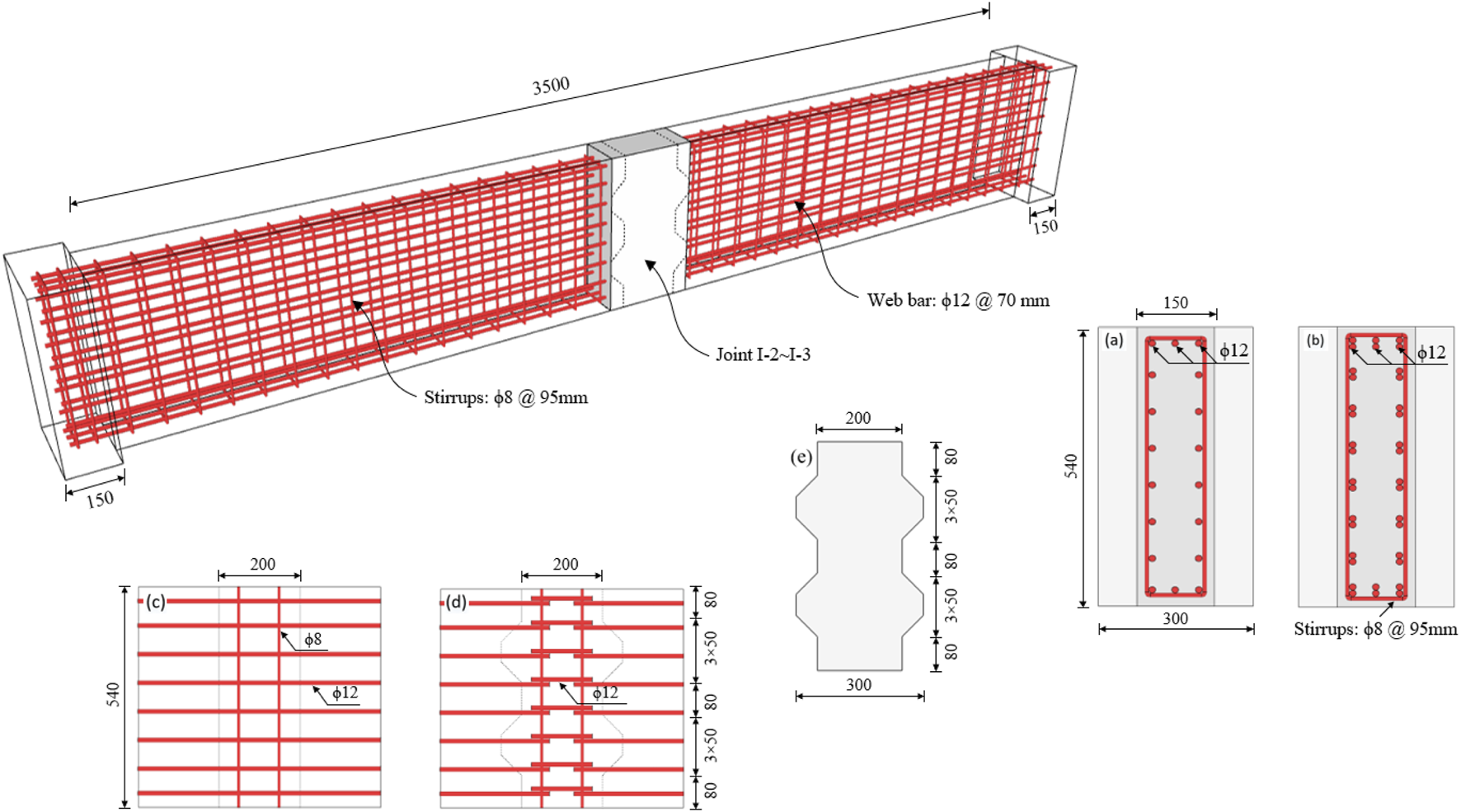
Schematic diagrams of in-plane specimens (unit: mm): (a) complete beam cross-section; (b) UHPC wet joint cross-section; (c) details of the complete beam specimen at the position corresponding to the rhombus wet joint; (d) details of rhombus wet joints; (e) rhombus wet joints.
FIGURE 2
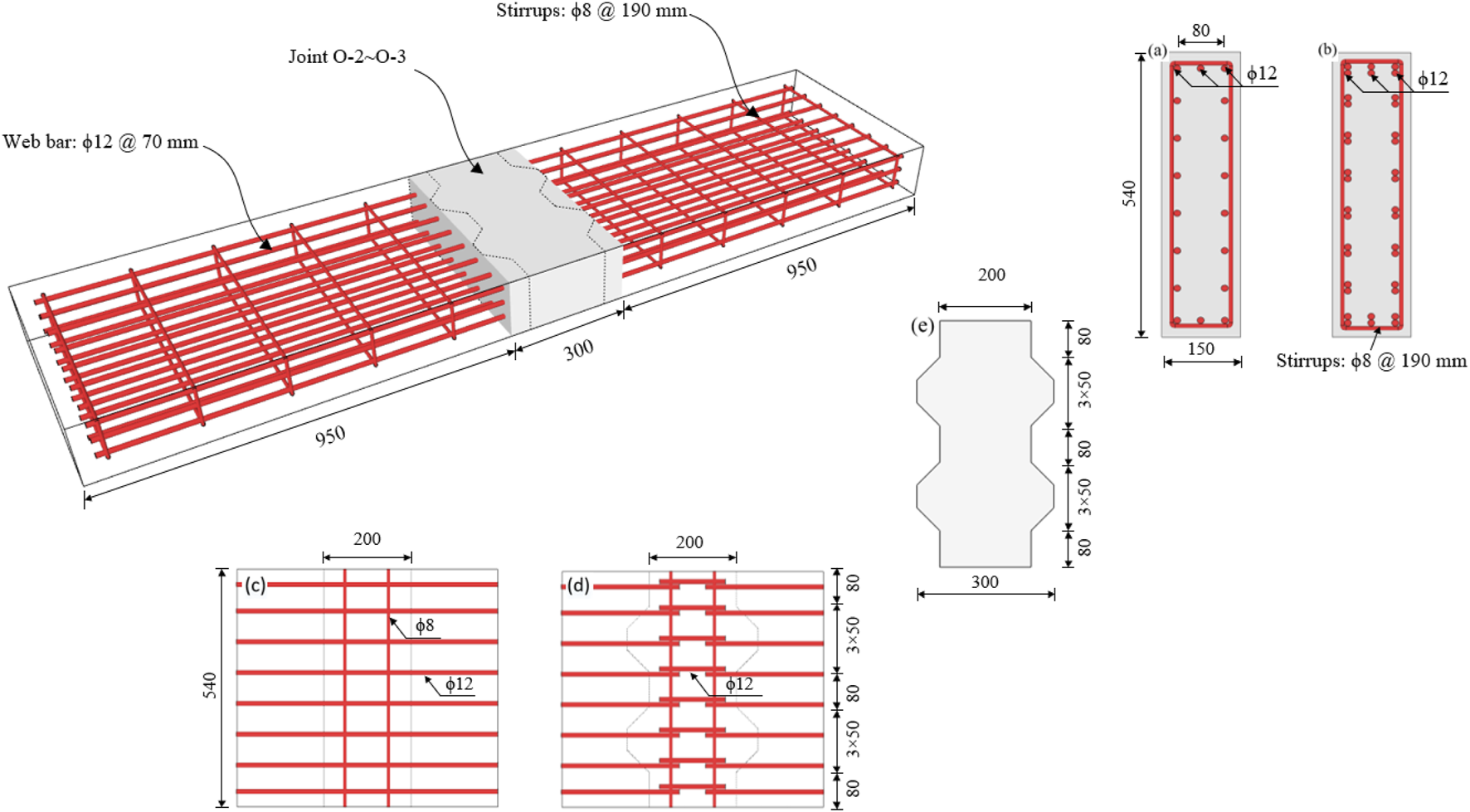
Schematic diagrams of out-of-plane specimens (unit: mm): (a) complete slab cross-section; (b) UHPC wet joint cross-section; (c) details of the complete slab specimen at the position corresponding to the rhombus wet joint; (d) details of rhombus wet joints; (e) rhombus wet joints.
It can be seen from Figure 1 that the in-plane specimen measures 3.8 m in length with a calculated length of 3.65 m, a width of 0.15 m, and a depth of 0.54 m. Due to the narrow width of the experimental beams, the aspect ratio of the beams is 25.3, similar to that of long columns. To prevent tilting during loading, the width of the specimen at both ends is extended to 0.3 m. Three HRB400 ribbed steel bars, each 12 mm in diameter with a spacing of 40 mm, are arranged at the top and bottom of the specimen. Additionally, two HRB400 ribbed steel bars (web steel bars) of 12 mm diameter are longitudinally arranged between the top and bottom of the specimen with a spacing of 70 mm. To prevent shear damage, stirrups with a diameter of 8 mm is placed at a spacing of 95 mm along the longitudinal direction of the beam. The longitudinal steel bar reinforcement ratio, stirrup reinforcement ratio, and the maintenance method of UHPC at the joints for the in-plane specimens are detailed in Table 1. As shown in Figure 1, the joint width of specimens I-2 to I-3 measures 0.3 m, and the steel bars arrangement at the UHPC wet joint matches that of the corresponding section of the complete in-plane specimen. However, it is important to note that the longitudinal steel reinforcement at the joint is in a disconnected state. To improve the continuity of the steel bars, steel bars of the same diameter are used to weld the steel bars of the two prefabricated portions, ensuring that the welding length of steel bars exceeds 10 times the diameter of the welding steel bars (where d represents the diameter of the welding steel bars).
As shown in Figure 2, the out-of-plane specimen has dimensions of 2.2 m in length, 0.15 m in width, and 0.54 m in height. The cross-sectional dimensions for the flexural static load experiments remain consistent with those of the in-plane specimens. However, there is an interchange of height and width, resulting in a distinct flexural form for the UHPC wet joint. To prevent shear failure, stirrups with a diameter of 8 mm are evenly spaced at intervals of 190 mm along the length of the slab. The arrangement of longitudinal steel bars and the construction details at the joints match those of the in-plane specimens. The longitudinal steel bar reinforcement ratio, stirrup reinforcement ratio, and the maintenance method of UHPC at the joints for the out-of-plane specimens are shown in Table 1.
2.2 Specimen preparation
In-plane and out-of-plane specimens made of UHPC with wet joints comprise two precast UHPC parts and one cast-in-place UHPC joint. Given the similarity in the fabrication process of in-plane and out-of-plane specimens, this paper will provide a detailed display and description of the fabrication process for in-plane specimens without delving into the fabrication of out-of-plane specimens.
It can be seen in Figure 3 that the process began with the assembly and welding of the steel mold plate, followed by placing the pre-tied reinforcing steel skeleton into the mold. To ensure a uniform distribution of the UHPC raw material within the steel mold plate and maintain the material’s mechanical properties, two high-frequency vibrators were used to apply appropriate vibrations during the UHPC injection process. After pouring the precast parts, the UHPC surface was covered with a membrane for natural maintenance lasting 48 h. As mentioned in reference Aaleti and Sritharan (2019), there may be a lack of appropriate mechanical connections between the unroughened interface of new and old UHPC, which could lead to weakened interface strength. The bonding between new and old UHPC needs to be established through sufficient surface roughness to provide resistance through shear friction mechanisms. Interface bonding can enhance the strength of the interface to resist stress caused by mechanical loads, differential shrinkage, and/or thermal effects, while maintaining extended service life performance. Therefore, once the UHPC had solidified, the mold was removed and the joint bonding surface of the prefabricated segments was chiseled, and the macroscopic weave depth measured by the sand-filling method was about 1.0∼5.0 mm (Aaleti and Sritharan, 2019). The prefabricated parts underwent steam curing at a temperature of 90°C for 48 h. The longitudinal steel bars protruding from the two precast parts were then welded together by means of short steel bars of the same diameter, followed immediately by the casting of the UHPC at the joints. Following the UHPC casting, each specimen was steam-conditioned or naturally cured according to the requirements. At this stage, the specimen was completed and prepared for experimentation. It is important to note that the production process of the complete specimen was relatively straightforward, involving only the cast-in-place production of components and steam curing.
FIGURE 3
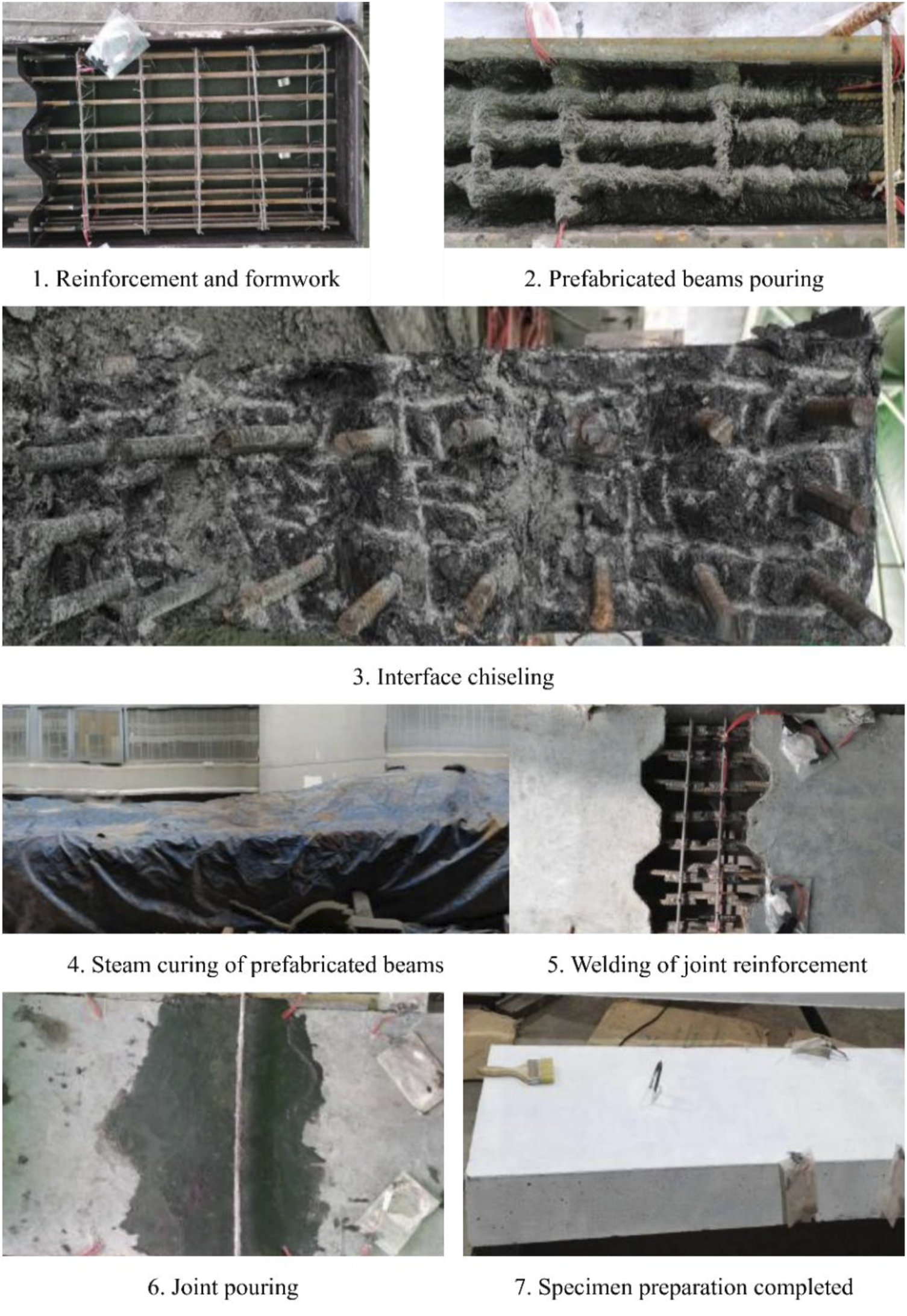
The fabrication process of experimental specimens.
2.3 Material properties
UHPC material employed in this study is UHPC150 provided by Hunan Xingguli Company. The steel fibers used are 13 mm in length, 0.2 mm in diameter, with an aspect ratio of 65 for the cylindrical straight steel fibers. The steel fiber content in the prefabricated parts is 2.0%. As mentioned in the introduction, the crack resistance performance at the interface is lower than that of the intact specimen, and the widest crack of the specimen appears at the interface. The discontinuity of the steel fibers at the interface weakens the bearing capacity and crack resistance of the specimen, while the continuity of the steel fibers can play a bridging role at the interface, improve the crack resistance performance of the interface, reduce the crack width, and enhance the stiffness and bearing capacity of the specimen (Jung et al., 2014; Zhao et al., 2022; Qiu et al., 2025; Lu et al., 2025). Therefore, considering the discontinuity of fibers at the joints, the UHPC mix at the joints consists of UHPC150 with a steel fiber content of 2.5% to enhance joint mechanical performance. During the casting process of the specimens, cubic or prismatic samples were prepared for testing. Compression tests, modulus of elasticity tests, and flexural tests were carried out to determine the mechanical properties of UHPC according to the Chinese code GB/T 31387 (AQSIQ SAC General Administration of Quality Supervision, 2015). The mechanical properties of UHPC are shown in Table 2. According to the French code NF P 18–470 (AFNOR, 2016), the tensile strength of UHPC can be obtained by converting the flexural test data, the equation is shown in Table 2. Furthermore, steel bars used in the experiments underwent material properties testing, and the results are summarized in Table 3.
TABLE 2
| Type of material | f cu (MPa) | E c (GPa) | f MOR (MPa) | f t (MPa) |
|---|---|---|---|---|
| UHPC150-20-1 | 151.36 | 46.43 | 24.56 | 7.51 |
| UHPC150-20-2 | 150.55 | 44.07 | 24.04 | 7.23 |
| UHPC150-25-Z | 159.07 | 45.45 | 25.13 | 8.35 |
| UHPC150-25-B | 139.06 | 41.68 | 24.33 | 6.93 |
Mechanical properties of UHPC.
Note: (1) ; (2) fcu is cubic compressive strength; fMOR is flexural strength; ft is direct tensile strength; UHPC150-20-i, denotes the ith batch of UHPC cast with 2.0% steel fiber dosing,i takes the values of 1,2; UHPC150-25-X denotes UHPC with 2.5% steel fibers, where Z denotes steam curing and B denotes natural curing.
TABLE 3
| D s (mm) | f y (MPa) | E s (GPa) | Φ |
|---|---|---|---|
| 8 | 441.2 | 200 | 24.3% |
| 12 | 462.3 | 200 | 25.4% |
Mechanical properties of steel rebar.
Note: Ds is diameter of steel bars; fy is yield strength; Es is elastic modulus of steel bars; and φ is elongation of steel bars.
2.4 Experimental setup and loading process
The loading diagram of in-plane and out-of-plane specimens are shown in Figures 4, 5, respectively. It can be seen from Figures 4, 5 that both ends of the specimen used a fixed hinge bearing and a movable hinge bearing to establish a simple support system. This loading system involved a 100-ton hydraulic actuator along with a 100-ton sinusoidal load cell to enable the application and control of the load. To implement the 4-point loading, a distribution beam was used to evenly distribute the load to the loading action points, maintaining a spacing of 0.7 m between the two loading points.
FIGURE 4
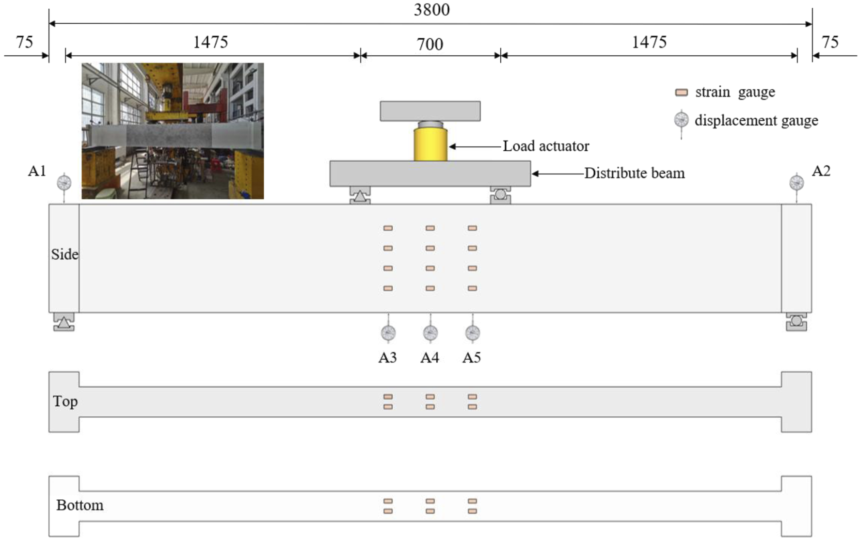
Schematic diagram of loading of in-plane specimens (Unit: mm).
FIGURE 5
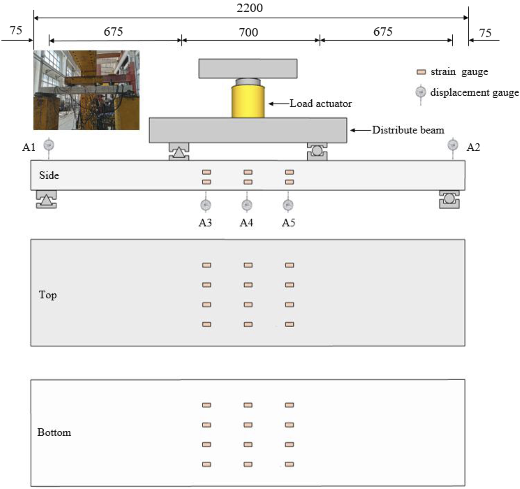
Schematic diagram of loading of out-of-plane specimens (Unit: mm).
To ensure the loading system and measuring instruments reach a normal working condition and eliminate initial inelastic deformation of the specimens, two preloading tests were conducted before the formal loading process. Each preload consisted of five stages, incrementally reaching up to 30% of the predicted cracking load. Following the preloading, formal loading began with each level’s load not exceeding 5% of the predicted peak load. The load increment for each level of the in-plane specimens was 4 kN, while for the out-of-plane specimens, it was 2 kN. Adjustments were made when the maximum crack width reached 0.3 mm. When the load could not be further increased,the load was adjusted based on a 1 mm displacement increase for each level until the completion of the load test. Displacement and strain, crack development, crack morphology, and crack width at the monitoring locations, i.e., the UHPC wet joint interface and the pure bending region, were observed and recorded during each loading stage.
As shown in Figures 4, 5, five vertical displacement gauges were positioned along the longitudinal direction of each specimen, both for in-plane and out-of-plane specimens. Two of these displacement gauges (A1 and A2) were installed at the support locations to eliminate the influence of support vertical deflection on the measurement outcomes. The remaining three displacements (A3, A4, and A5) were placed at three designated cross-sections within the pure bending section. Specifically, displacement gauge A2 was situated at the mid-span section of the specimen, while A1 and A3 were positioned on the left and right sides of the specimen, 0.25 m away from A2. To accurately measure strain in the pure bending section and monitor crack development in real-time, multiple strain gauges were placed laterally across three distinct sections. To measure the strain of UHPC, 12 strain gauges were arranged to each lateral surface of the in-plane specimen, with 6 strain gauges on both the upper and lower surfaces. Similarly, 6 strain gauges were attached to each lateral surface of the out-of-plane specimen, with additional 12 strain gauges on both upper and lower surfaces. Furthermore, strain gauges for measuring strain in the longitudinal steel bars were positioned at three specific cross-sections. In each cross-section, one strain gauge was allocated to the bottom tensile steel bars and one to the top compressive steel bars.
3 Experimental results and discussions
3.1 Failure mode and crack distribution
All the specimens experienced typical cross-section bending damage, with the damage morphology of the in-plane and out-of-plane specimens shown in Figure 6a as follows: the primary crack was situated in the pure bending region at the midpoint of the span, with all steel fibers at the main crack being pulled out or detached, resulting in cracks wider than 2 cm, as shown in Figure 6b. The number of cracks in the bending and shear segments was relatively small, and there were no conspicuous shear diagonal cracks. The UHPC in the compression zone within the pure bending section at the middle of the span of the test specimen collapsed. The damage process of the complete specimen unfolded as follows: prior to the emergence of the initial crack, the deflection of the specimen exhibited a linear increase with the rising load. The first crack appeared within the pure bending region of the span, and as loading continued, the length and width of the crack gradually expanded. Furthermore, the crack’s width experienced a rapid surge as the ultimate load approached. Upon reaching the peak load, the load sensor’s reading could no longer increase, prompting the load to be controlled based on displacement. After several load increments, the UHPC in the compression zone collapsed, resulting in specimen damage. The damage process of the joint specimen closely mirrored that of the complete specimen, except that the initial crack appears at the joint interface, and the early-stage cracks mainly develop at the joint interface.
FIGURE 6
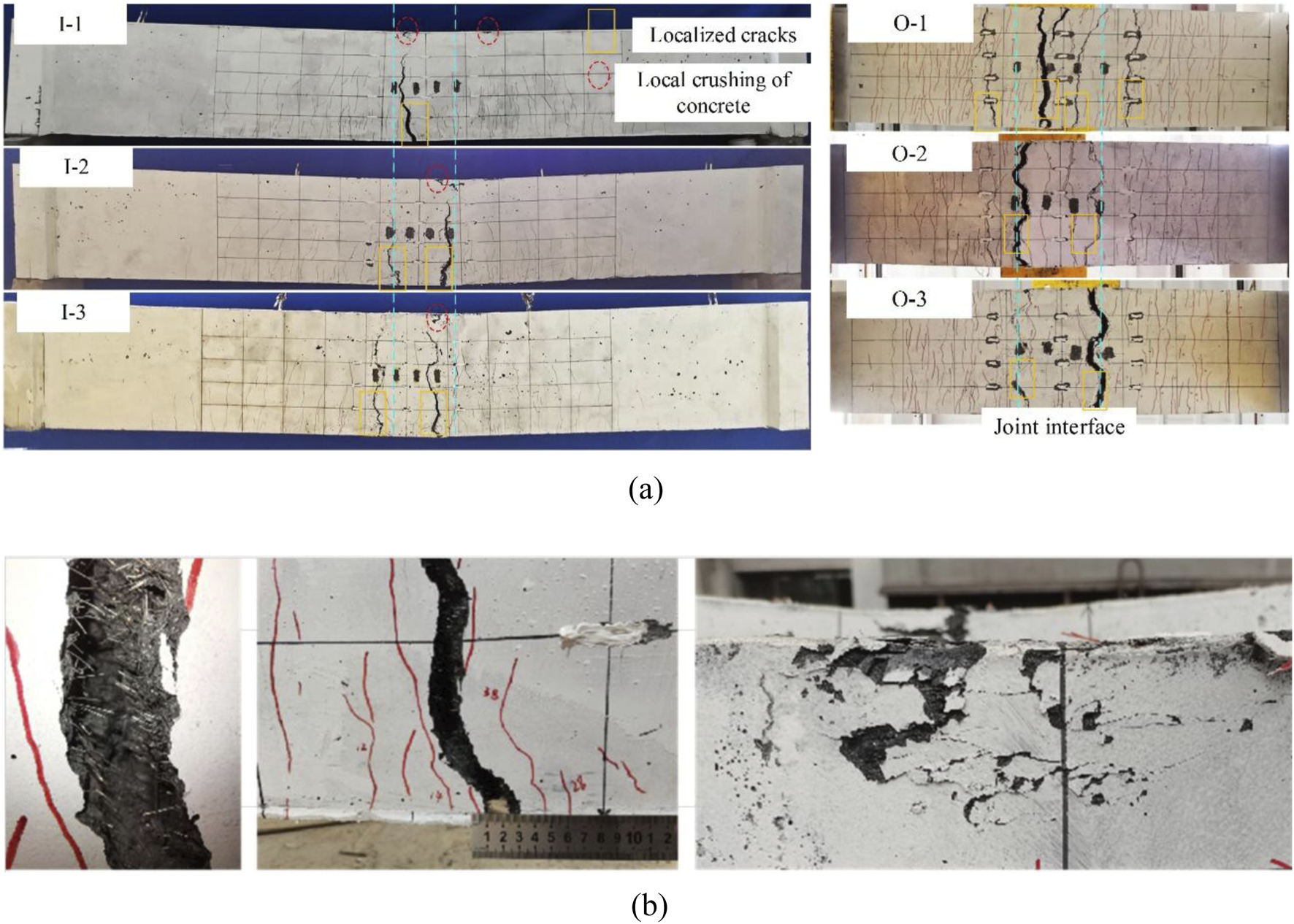
Failure modes: (a) Overall failure mode; (b) main crack and crushing.
It can be seen from Figure 7 that the distribution of cracks at maximum widths of 0.05 mm, 0.10 mm, 0.20 mm, 0.30 mm, and at failure for both in-plane and out-of-plane specimens, showing the cracking behavior of the specimens. Typically, a crack width of 0.05 mm is crucial for the durability design of UHPC (Qiu et al., 2020a; Rafiee, 2012; Qiu et al., 2020b). It is can also be seen from Figure 7 that there is a relatively uniform progression of crack numbers on the complete specimen surface. As the maximum crack width reaches 0.3 mm, the crack count stabilizes, with most crack formation occurring in the initial loading stages. In comparison to the complete specimen, the jointed specimen exhibits fewer cracks, primarily due to its lower structural integrity and the weak joint surface. Once a crack initiates on the joint surface, it tends to concentrate and expand predominantly in the section, while crack growth in other areas of the specimen proceeds at a slower pace. The quantity of cracks is mainly influenced by the maximum crack width, which can extend up to 0.2 mm. The cracking pattern and development trend in the two jointed specimens are similar. The presence of the joint significantly impacts the crack development trend on the specimen’s surface. However, the maintenance approach of UHPC at the joint has a relatively minor effect on the crack development trend on the specimen’s surface.
FIGURE 7
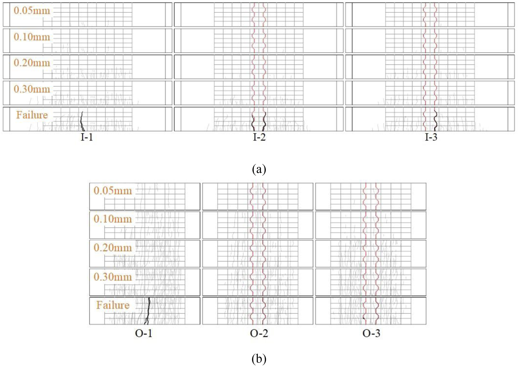
Distribution of cracks: (a) In-plane specimens; (b) Out-of-plane specimens.
Similar to the in-plane specimens, the number of cracks in the out-of-plane jointed specimens was less compared to the out-of-plane complete specimen. Crack propagation in both the complete and jointed specimens mainly occurred during the initial loading phase, from the onset of loading until reaching a maximum crack width of 0.2 mm. During the later loading stages, the development of crack width was more gradual compared to the in-plane specimen. The pattern of crack evolution in both the complete and jointed specimens remained largely consistent, with the joint having a relatively minor influence on the crack propagation trend in the out-of-plane specimen.
3.2 Load-deflection curves
The load deflection curves of the in-plane and out-of-plane specimens are shown in Figure 8. These curves exhibit typical bending characteristics and can be broadly categorized into three stages: (1) During the elastic stage, the deflection prior to initial cracking increased linearly with the applied load, and the curve displayed a larger but consistent slope, which indicated that the specimen only produced elastic deformation under the action of load and the flexural rigidity of the specimen basically remained constant; (2) During the crack development stage, As cracks emerged and the load intensified, the slope of the curve decreased, indicating that the specimen experienced some degree of plastic deformation leading to a reduction in stiffness. (3) During the yield stage, there was a noticeable change in the curve’s direction, followed by a phase where the load remained relatively unchanged while the deflection continued to increase. This behavior demonstrated the specimen’s capacity for plastic deformation (Yang et al., 2010; Qi et al., 2020).
FIGURE 8
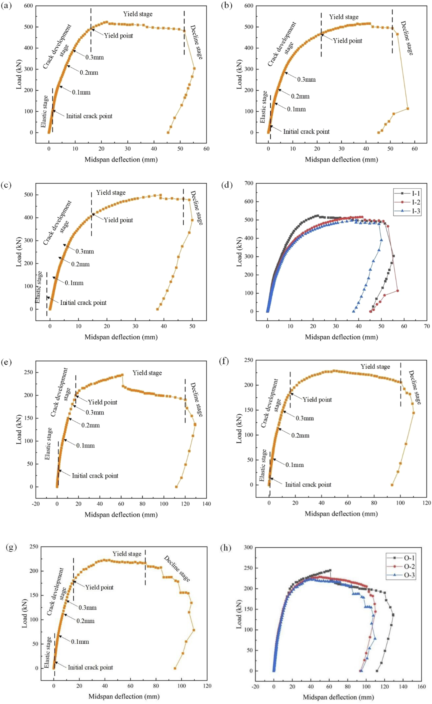
Load-Deflection Curves: (a) specimen I-1; (b) specimen I-2; (c) specimen I-3; (d) Comparison curves for in-plane test specimens; (e) specimen O-1; (f) specimen O-2; (g) specimen O-3; (h) Comparison curves for out-of-plane test specimens.
When comparing the load-deflection curves of the jointed specimen and the complete specimen, it is can be seen from Figure 8 that the overall slope of the load-deflection curve for the jointed specimen is smaller than that of the complete specimen. With the same maximum crack width, the complete specimen can withstand a much higher load than the jointed specimen. The difference in load between the two jointed specimens is minimal, indicating that the stiffness of the jointed specimen is inferior to that of the complete specimen. The joints reduces the stiffness of the specimen, and the curing method of UHPC at the joint does not have a significant impact on the stiffness of the jointed specimen.
The corresponding loads and mid-span displacements of the specimens in both the in-plane and out-of-plane specimens at various states were shown in Table 4. The cracking loads of in-plane jointed specimens I-2 and I-3 are 45.9 kN and 52.5 kN, respectively. The cracking loads of out-of-plane jointed specimens O-2 and O-3 are 22.0 kN and 25.0 kN, respectively. These findings suggest that the steam curing of UHPC at the joints had a adverse effect on the initial cracking behavior of the jointed specimens. Compared to the complete specimens, the wet joints expedited the initial cracking behavior of the members. This suggests that the chiseling at the interface of the experimental specimens, along with the augmentation of steel fiber contents in the joints, did not notably enhance the initial cracking resistance of the jointed specimens. It is noteworthy that the joints have no significant impact on the structural integrity or the stiffness of the specimens. As shown in Table 4, the flexural capacity of the in-plane jointed specimens I-2 and I-3 only decreased by 1.4% and 4.7%, respectively, compared to the complete specimen I-1. The flexural capacity of the out-of-plane jointed specimens O-2 and O-3 decreased by only 6.5% and 9.0%, respectively, compared to the complete O-1. This can be attributed to hand-chiseling treatment and the enhancement of longitudinal steel bats continuity achieved through the utilization of short welding steel bars at the joints. Furthermore, the curing methods of UHPC at the joints did not significantly enhance the flexural capacity of the jointed specimens. In addition, it can be seen from Figure 8 and Table 4 that the in-plane specimens have higher flexural capacity compared to the out-of-plane specimens. And due to the larger thickness of the in-plane specimens, they can have smaller deflection during the test process, which reflects that the stiffness of the in-plane specimens is better than that of the out of plane specimens.
TABLE 4
| Specimen | Cracking state | Yielding state | Peak state | Limit state | ||||
|---|---|---|---|---|---|---|---|---|
| P cr (kN) | Δcr (mm) | P y(kN) | Δy (mm) | P p (kN) | Δp (mm) | P u (kN) | Δu (mm) | |
| I-1 | 100.3 | 1.42 | 491.2 | 16.03 | 523.1 | 22.08 | 480.7 | 51.55 |
| I-2 | 45.9 | 0.76 | 473.0 | 22.6 | 515.9 | 40.6 | 493.6 | 50.88 |
| I-3 | 52.5 | 0.89 | 430.7 | 17.69 | 498.5 | 38.86 | 477.7 | 48.95 |
| O-1 | 36.0 | 1.32 | 199.9 | 17.37 | 244.6 | 61.12 | 190.1 | 120.15 |
| O-2 | 22.0 | 0.74 | 195.1 | 19.1 | 228.7 | 49.42 | 205.3 | 100.47 |
| O-3 | 25.0 | 1.14 | 192.3 | 19.26 | 222.7 | 39.4 | 216.4 | 71.56 |
Summary of the flexural test results of the specimens.
Note: Pcr is the initial cracking load; Δcr is the mid-span deflection at the initial cracking load; Py is the load when the longitudinal steel bar yields; Δy is the mid-span deflection when the longitudinal steel bar yields;Pp is the peak load; Δp is the mid-span deflection corresponding to the peak load; Pu is the ultimate load; Δu is the mid-span deflection corresponding to the ultimate load, respectively.
3.3 Load-longitudinal steel bar strain curve
The strain variation of the tensile steel bars at the mid-span section of the out-of-plane specimens was shown in Figure 9. It can be observed from Figure 9 that the strains of the tensile steel bars at mid-span in both the jointed and complete specimens are essentially consistent before reaching the yield point. And the loads when the steel bars yielded are generally similar. This can be attributed to the utilization of short welding steel bars at the joint of the specimen, which effectively incorporated the short welding steel bars into the load-bearing mechanism. The welding operation greatly enhanced the continuity and load-carrying capacity of the steel bars at the joint. However, the strain curves of mid-span tensile steel bars in in-plane specimens exhibites a different phenomenon as load changes. As shown in Figure 10, there is a notable disparity in the strains of mid-span cross-section tensile steel bars between the jointed specimen and the complete specimen after cracking occured in the jointed specimen (around a load of 50 kN). Furthermore, as the width of cracks at the joint interface of the jointed specimen expanded, the growth rate of strains of the mid-span cross-section tensile steel bars increased significantly, surpassing that of the complete specimen. The main reason can be attributed to the presence of a weaker section at the joint interface in the jointed specimen.
FIGURE 9
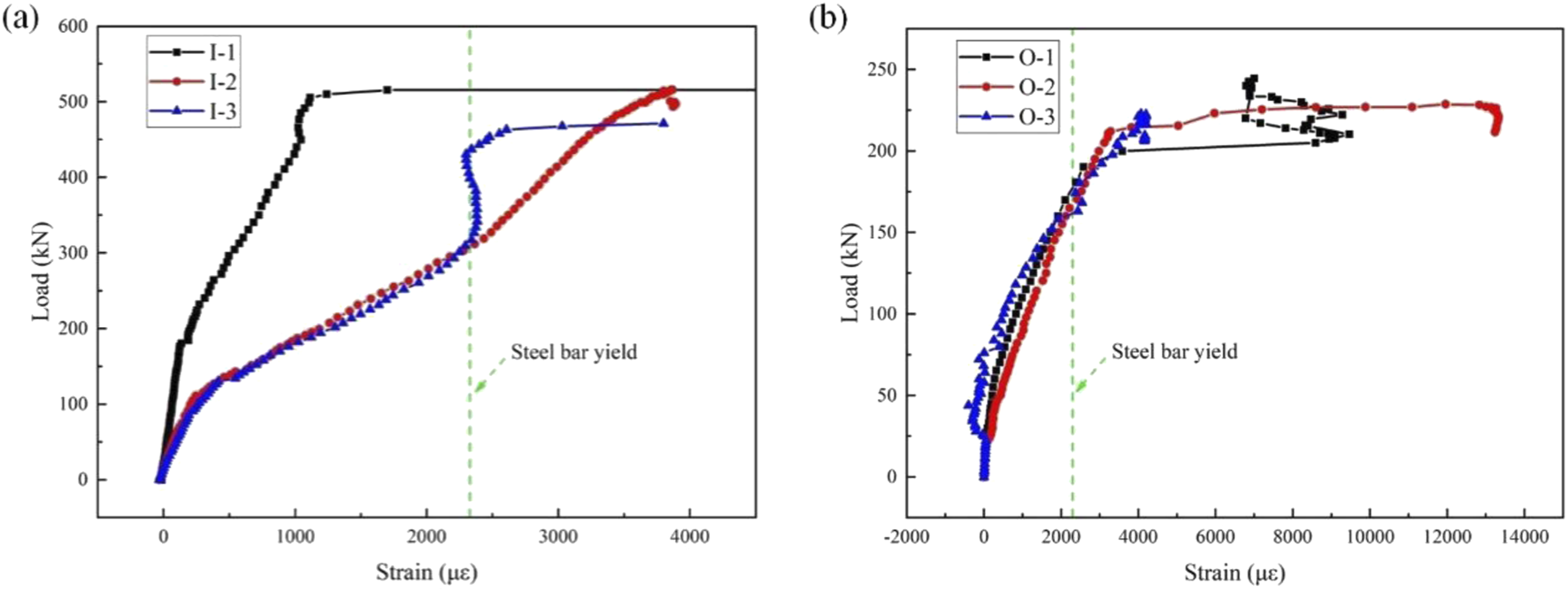
Load-longitudinal steel bar strain curve: (a) In-plane specimens; (b) Out-of-plane specimens.
FIGURE 10
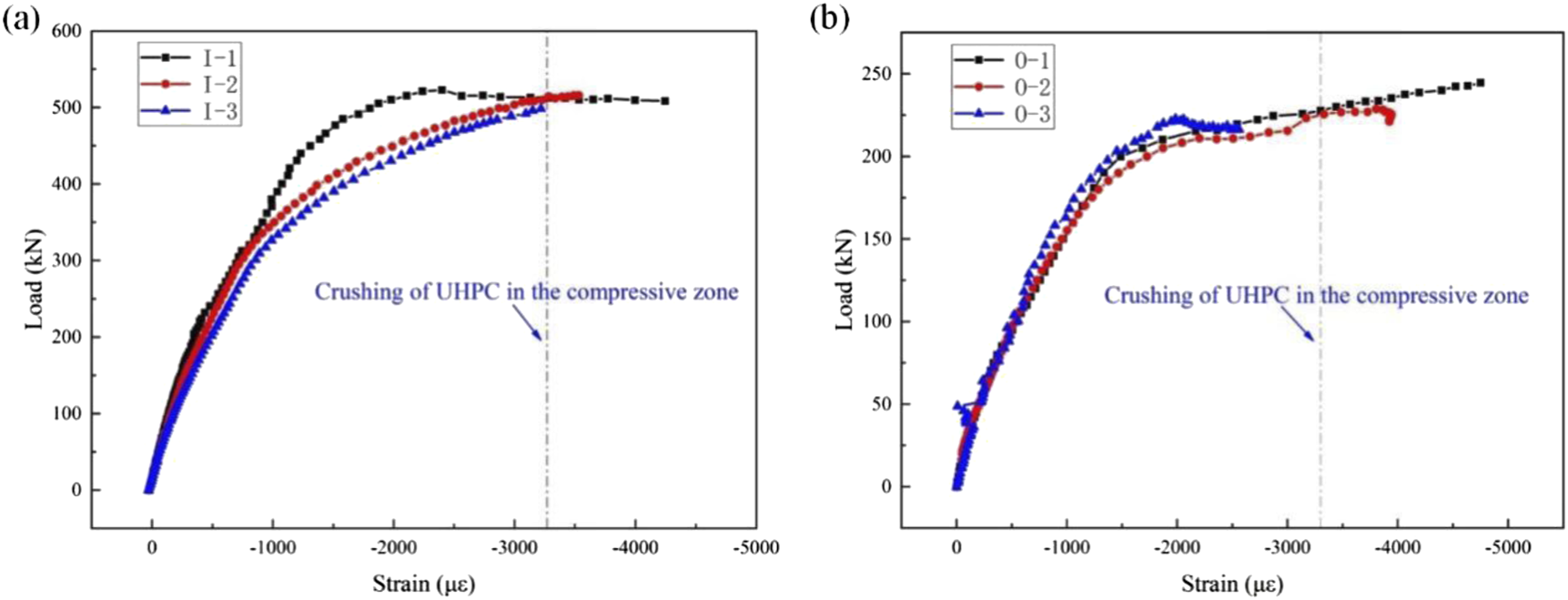
Load-UHPC compressive strain curve: (a) In-plane specimens; (b) Out-of-plane specimens.
During the crack development stage, the jointed specimen exhibited a higher crack width and number compared to the complete specimen. This directly led to premature debonding of UHPC at the joint interface and a increase in the participation of tensile steel bars in bearing the load. Therefore, the strain growth rate of the tensile steel bars across the jointed specimen was significantly greater than that of the complete specimen. However, the absence of this phenomenon in the out-of-plane specimen can be attributed to the bending form of the specimen (slab), which reduces the degree of mechanical property weakening caused by the interface between the joint and prefabricated part. The inversion of the wet joint in the UHPC allows the tensile capacity to be provided by an entire row of longitudinal steel bars at the bottom of the slab. In contrast, the in-plane specimens only have three longitudinal steel bars at the bottom of the beam. The final strains in both the in- and out-of-plane specimens reached 2,300 microstrain, indicating that the steel bars had yielded.
3.4 UHPC compressive strain
The variation of UHPC compressive strain with load at the mid-span section of each specimen during the loading process is shown in Figure 10. It can be seen in Figure 10 that UHPC compressive strain of the in-plane specimens exhibits a gradual increase with the applied load during the initial loading phase. After the occurrence of cracking, the compressive strain experiences a slower increment with the load, aligning with the development trend observed in the load-deflection curve. For the out-of-plane specimens, the evolution of UHPC compressive strain across the span of the three specimens demonstrates a consistent pattern. The load-deflection curves display a gradual change after the initial crack, tending towards a horizontal direction as approaching the ultimate load. By the late loading stage, the UHPC compressive strain in each specimen had reached approximately 3,500 microstrains, indicating the crushing of UHPC in the compression zone. In summary, the existence of joints and the maintenance method of UHPC at the joints do not notably impact the trend of compressive strain in the UHPC across the span in relation to the applied load magnitude.
In addition, it can be seen from Figure 10 that there are some differences in the compression curves of UHPC in the compression zone between the in-plane and out-of-plane specimens. After reaching a load of 200 kN, the growth rate of compressive strain in the UHPC compression zone of the out-of-plane specimen significantly decreases. This is likely due to the lower flexural stiffness of the specimen, faster crack development, and the early entry of tensile steel bars into the yield stage, resulting in a significant decline in flexural capacity. Due to the stronger stiffness, the in-plane specimen has a smaller degree of deflection in the early stage of loading, and the crack width is smaller than that of the out-of-plane specimen. Therefore, the attenuation rate of bearing capacity is slower than that of the out of plane specimen.
3.5 UHPC strain distribution in mid-span section
Strain gauges were applied in the pure bending section where cracks primarily developed in the specimens. As the specimens cracked, some of the cracks extended through the strain gauges, causing damage to these strain gauges. Therefore, the strain data at the onset of cracking for each member was utilized to plot the curve depicting the variation of UHPC strain with the height of the cross-section. The curves depicting UHPC strain versus beam section height for the mid-span section of the pure bending segment of in-plane and out-of-plane specimens are shown in Figure 11. It can be seen from Figure 11 that the UHPC strain exhibits an approximately linear distribution with respect to the section height at each loading level, with only minor deviations in the data from individual strain gauges. This indicates that the specimen aligns with the cross-sectional assumption in both the positive and negative bending moment regions. In this paper, the bottom surface of the beam is considered as the starting surface of the beam height, with a height of 0 mm. The top heights of the in-plane and out of plane specimens are 540 mm and 150 mm, respectively.
FIGURE 11
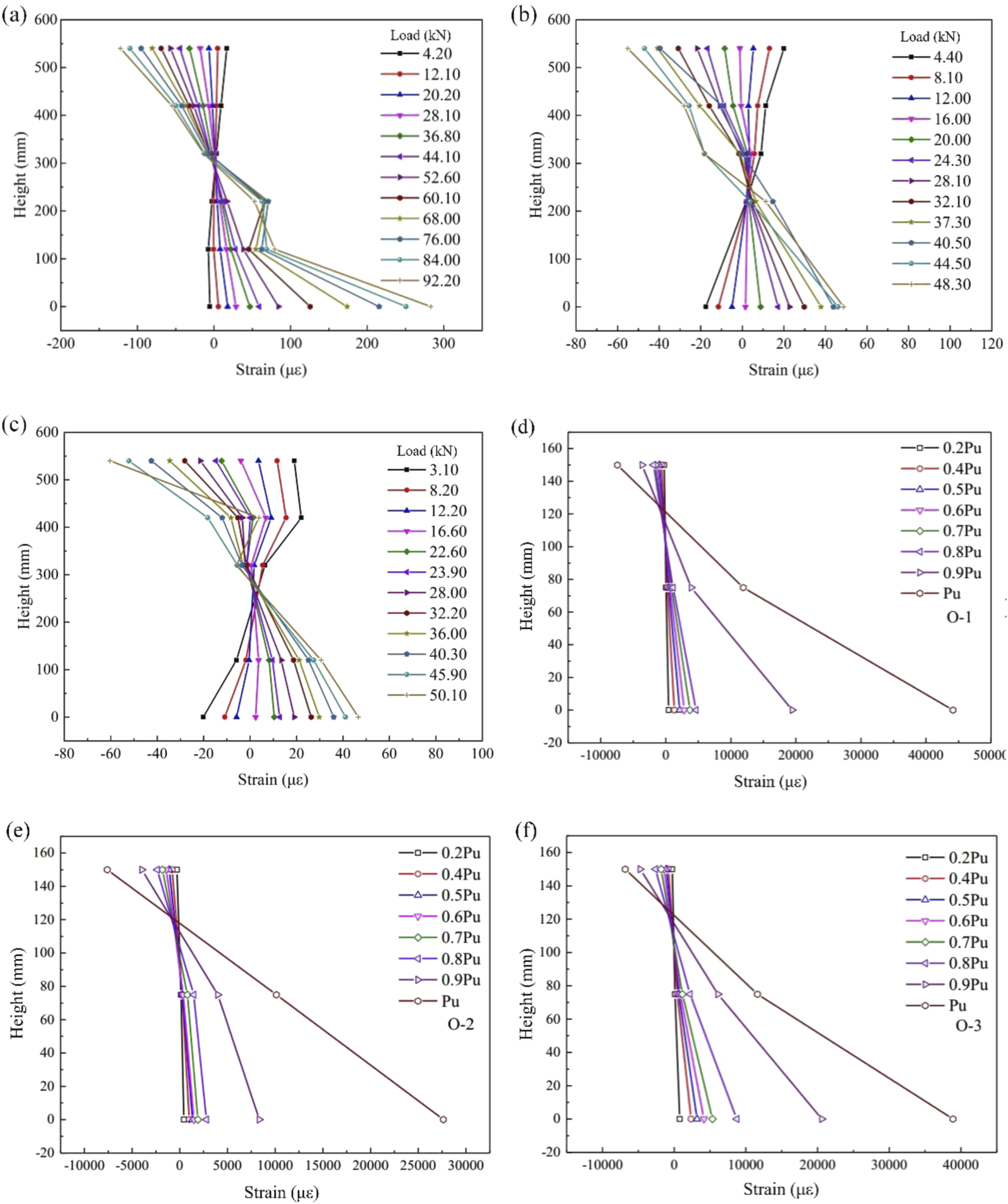
UHPC strain variation curve with height: (a) Specimen I-1; (b) Specimen I-2; (c) Specimen I-3; (d) Specimen O-1; (e) Specimen O-2; (f) Specimen O-3.
3.6 Ductility
The ductility of a flexural member can be quantified using the ductility coefficient, typically determined through the energy method and the geometric graphing method. In this paper, the ductility coefficients of the test specimens are calculated using the geometric graphing method as described in Figure 12 (Zhang and Huang, 2005).
FIGURE 12
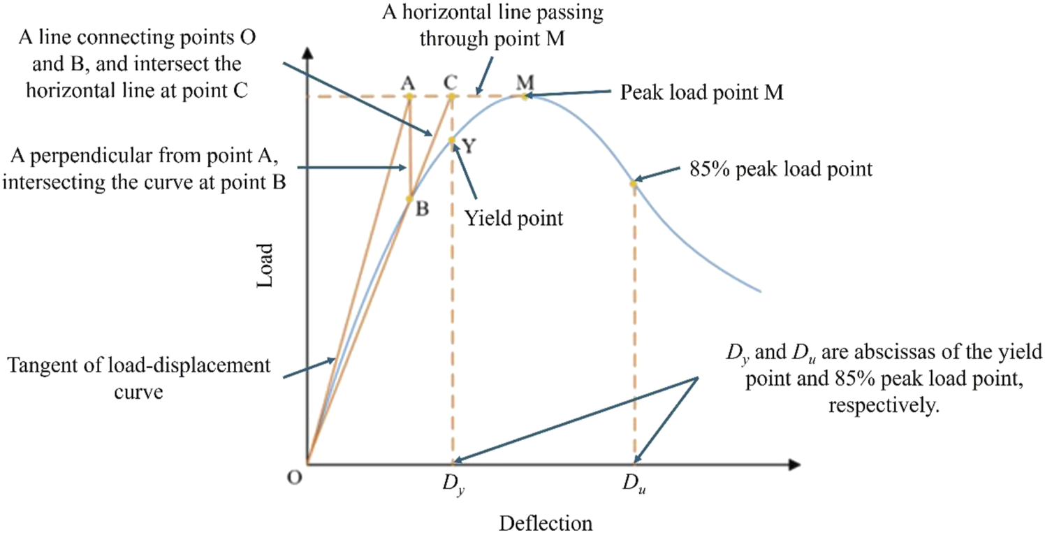
Calculation model of ductility.
As shown in Figure 12, draw a horizontal line passing through the peak load point M. Meanwhile, draw a tangent of the load-deflection curve from point O intersecting with the horizontal line at point A. Then, draw a perpendicular from point A intersecting with the load-deflection curve at point B. Draw a line connecting points O and B and extend it to intersect with the horizontal line at point C. Draw a perpendicular from point C intersecting with the curve at point Y, which is the yield point. Dy and Du, which are abscissas of the yield and 85% peak load points, respectively, represent the deflection of the yield and 85% peak load points, respectively. The ductility coefficient μ can be calculated by Equation 1; (Zhang et al., 2020b; Pam et al., 2001; Ke et al., 2023). During this analysis, the applied load for each specimen was gradually reduced to 0 at the end of the test, so that an accurate value of Du could be obtained.
The results of the calculations are presented in Table 5. It is observed that the ductility coefficients of the complete specimens exceed those of the jointed specimens. Furthermore, the ductility coefficients of the members with UHPC steam-conditioned at the joints surpass those of the members naturally conditioned with UHPC at the joints. This observation suggests that the presence of joints diminishes the ductility of the members. Moreover, the method of UHPC curing at the joints impacts the ductility of the specimens, with the ductility of members cured by steam curing outperforming that of naturally cured members.
TABLE 5
| Speciment | D y (mm) | D u (mm) | μ |
|---|---|---|---|
| I-1 | 11.6 | 53.1 | 4.58 |
| I-2 | 12.5 | 53.5 | 4.28 |
| I-3 | 12.1 | 49.2 | 4.07 |
| O-1 | 10.1 | 83.1 | 8.23 |
| O-2 | 12.2 | 88.2 | 7.23 |
| O-3 | 13.6 | 85.0 | 6.25 |
Calculation results of ductility.
It can also be seen from Table 5 that the ductility of the out-of-plane specimens is better than that of the in plane specimens. As mentioned above, the degree of bending deformation of the out-of-plane specimens is greater than that of the in plane specimens. When the load is greater than 200 kN, the steel bars of the out-of-plane specimens are close to yielding, and the degree of crack development is greater than that of the in plane specimens, which leads to more participation of steel bars in the deformation of the specimens. In addition, due to the lower stiffness and attenuation of the flexural capacity of the out of plane specimens, the deflection of the specimens between the yield point and peak load point increases more than that of the in-plane specimens, resulting in greater ductility of the out-of-plane specimens.
4 Flexural capacity calulation
4.1 Existing calculation method
Currently, there is no specific equation for calculating the flexural capacity of UHPC joint slabs and UHPC joint beams in domestic and international codes and regulations. However, researchers have conducted relevant studies and proposed equations based on experimental observations and theoretical research, offering valuable reference and practical significance.
Jia et al. (2021) modeled UHPC beams with rectangular wet joints and assumed the stress distribution as illustrated in Figure 13a, leading to the derivation of the following bearing capacity, as shown in Equation 2.where fcu represents the cubic compressive strength of UHPC; b and h denote the width and height of the beam, respectively; xc signifies the height of the compression zone of UHPC; fy and As stand for the yield strength and area of the tensile steel bars, respectively; fy’and As’represent the yield strength and area of the compression steel bars, respectively; ft indicates the tensile strength of UHPC; α is the equivalent rectangular stress coefficient, assumed to be 0.92; h0 is the effective height of the section; a’ denotes the distance from the center of the compression steel bar to the edge of compression zone; a represents the distance from the center of the tensile steel bar to the edge of tension zone; and Mu is the theoretically calculated value of flexural load capacity.
FIGURE 13
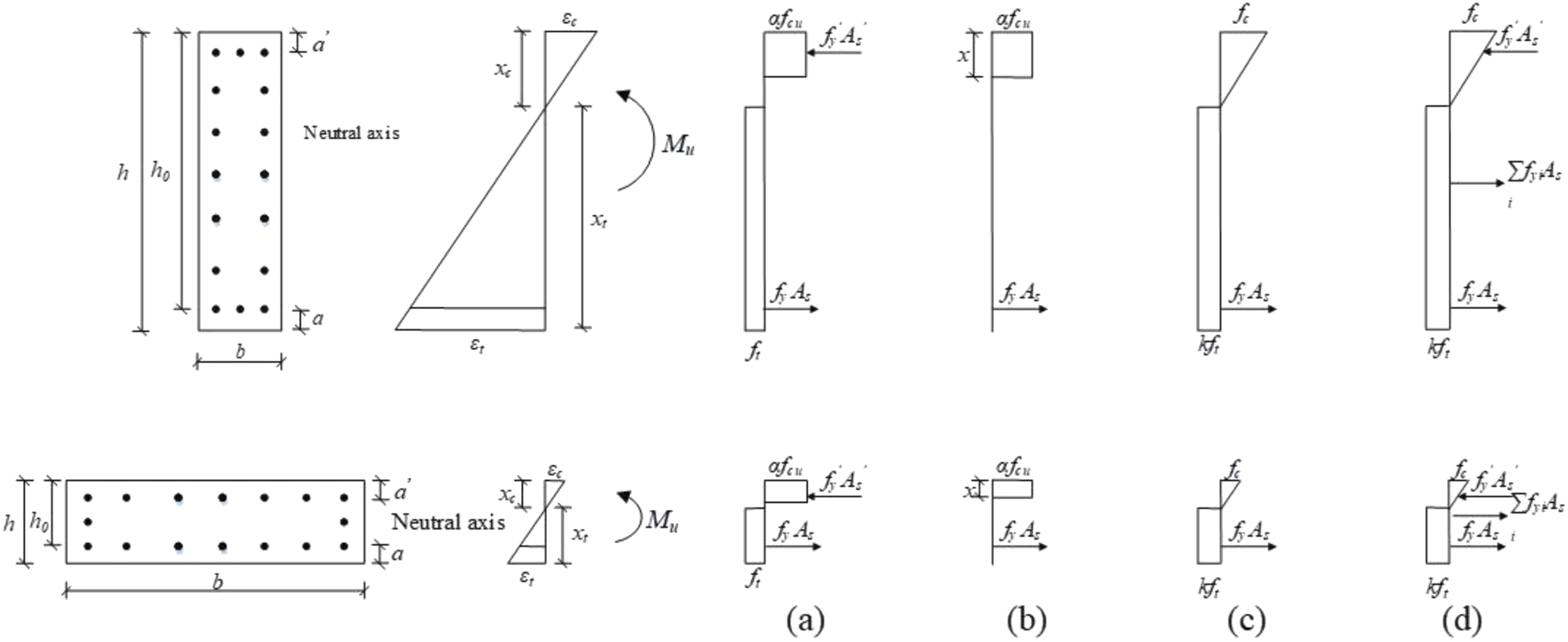
Cross-section strain and stress distribution: (a)Jia et al. (2021); (b)Yuan et al. (2020); (c)Yue et al. (2023); (d) This paper.
To explore the performance of UHPC beams with rectangular wet joints, an experimental study was conducted by Yuan et al. (2020). Based on the stress distributions shown in Figure 13b, a calculation equation for determining the bearing capacity of jointed beams was proposed, as shown in Equation 3.
Yue et al. (2023) conducted foot-scale modeling tests on UHPC panels with dovetail and comb wet joints. The stress distribution was assumed as shown in Figure 13c and derived Equation 4.where fc represents the axial compressive strength of UHPC, which is 0.9 times the cubic compressive strength fcu; k denotes the discount factor for the tensile strength of UHPC.
The flexural capacity of the specimens in this study was calculated using the aforementioned methods, and the results were shown in Table 6. The flexural capacity values listed in the table represent the measured and calculated values for the actual damaged cross-sections of the specimens. It is worth noting that the equations introduced by Jia et al. (2021) and Yuan et al. (2020) are not employed to determine the flexural capacity of the entire cast-in sections, as they are specifically designed for the jointed sections.
TABLE 6
| Specimen | Experimental values M(kN·m) |
calculation values Mu (kN·m) | |||||||
|---|---|---|---|---|---|---|---|---|---|
| Jia et al. (2021) | Yuan et al. (2020) | Yue et al. (2023) | This paper | ||||||
| M u | M u/M | M u | M u/M | M u | M u/M | M u | M u/M | ||
| I-1 | 385.8 | — | — | — | — | 220.2 | 0.571 | 380.0 | 0.985 |
| I-2 | 380.5 | 229.3 | 0.603 | 78.6 | 0.207 | 109.6 | 0.288 | 315.3 | 0.829 |
| I-3 | 367.6 | 217.5 | 0.592 | 78.5 | 0.214 | 107.0 | 0.291 | 307.0 | 0.835 |
| O-1 | 82.6 | — | — | — | — | 113.9 | 1.379 | 83.8 | 1.014 |
| O-2 | 77.2 | 76.75 | 0.994 | 46.9 | 0.608 | 54.6 | 0.707 | 70.0 | 0.907 |
| O-3 | 75.2 | 73.40 | 0.976 | 46.8 | 0.622 | 53.8 | 0.715 | 67.8 | 0.902 |
| Average value | 0.791 | 0.412 | 0.659 | 0.912 | |||||
| Coefficient of variation | 0.491 | 0.982 | 1.362 | 0.186 | |||||
Flexural capacity calculation results.
As shown in Table 6, the computed values from the current equations demonstrate a low level of agreement with the experimental data, indicating unsatisfactory predictions. However, it is noteworthy that the predictions for the out-of-plane specimens are more accurate compared to those for the in-plane specimens. The reason for not achieving satisfactory prediction results is that all equations suggested by the aforementioned scholars overlook the contribution of the web steel bars. In cases of out-of-plane specimens with a lower web steel bar reinforcement ratio, the contribution of web steel bars is less compared to in-plane specimens with a higher web bar reinforcement ratio, resulting in better prediction accuracy. The web steel bars play a beneficial role in enhancing the stiffness of the reinforcement structure and restricting crack propagation in the tension zone, consequently enhancing the flexural capacity of the specimens. In the test conducted by Jia et al. (2021) on UHPC beams with rectangular wet joints, the flexural capacity of UHPC jointed beams with girders was 256.2 kN, while that of UHPC jointed beams without girders was 197.4 kN. The ratio of the flexural capacity for UHPC jointed beams with and without web steel bars was 1.30, indicating the significant contribution of web steel bars to the flexural capacity of UHPC specimens. In order to predict more accurately the flexural capacity of UHPC joint specimens with web steel bars, it is necessary to propose a new calculation method that considers the flexural contribution of web steel bars.
4.2 Calculation method considering the contribution of web steel bars
Drawing from the experimental findings and incorporating existing research outcomes, the stress distribution of the section at the limit state is shown in Figure 13d, with the following assumptions: (1) The UHPC flexural specimens adhere to the cross-sectional assumption for specimen cross-sections both before and after deformation and cracking. (2) Ignoring the shear deformation and axial deformation of the specimens under vertical forces. (3) There is no significant relative slip between the steel bars and UHPC. (4) The steel bar in tensile zone yields, and the tensile stress of UHPC is uniformly considered as kft (Xiao et al., 2021; Hwang and Park, 2014). Previous studies have shown that the reduction factor k ranges from 0.2 to 0.6. When the specimen is a complete specimen without joints, it means that the tensile strength does not need to be reduced, that is, k = 1.0. As k decreases, the interfacial bonding strength also decreases (Hwang and Park, 2014). Therefore, according to the definition in reference (Hwang and Park, 2014), specimens I-2 and I-3 have weaker mechanical interlocking at the rhombus wet joints than slabs O-2 and O-3, k for specimens I-2 and I-3 is taken as 0.4. For specimens O-2 and O-3, k is taken as 0.6. And for specimens I-1 and O-1, k is taken as 1.0.
Based on the section equilibrium condition, the following flexural capacity can be calculated by Equation 5.where fyi represents the stress of the ith layer of web steel bars, calculated through section strain; Asi denotes the area of the ith layer of web steel bars; hsi is the distance from the ith layer of steel bar to the neutral axis; other symbols carry the same meanings as mentioned earlier.
The results obtained from the proposed calculation method, which takes into account the contribution of web steel bars to flexural capacity, are shown in Table 6. A comparison with other methods reveals that the calculated values using our approach exhibit the closest agreement with experimental values, and also demonstrate lower dispersion.
5 Conclusion
This paper presents an experimental study on the flexural performance of UHPC in-plane and out-of-plane specimens with rhombus wet joints. The conclusions drawn are as follows.
1. The performance of the complete specimens is superior to that of the jointed specimens, primarily in terms of stiffness and ductility. The complete specimens exhibit higher stiffness and better ductility. The joints alters the crack propagation trend in the in-plane specimens but has a minimal impact on the crack propagation trend in the out-of-plane specimens.
2. Steam curing for the joints of UHPC in jointed specimens is expected to have an adeverse effect on the initial cracking behavior. Furthermore, it does not significantly improve the stiffness and flexural capacity of the jointed specimens. However, in terms of ductility, the ductility of jointed specimens with steam-cured joints is better than that of jointed specimens with naturally cured joints.
3. Compared to the complete specimens, the flexural capacity of the jointed specimens only decreases by 1.4%–9.0%. This indicates that the chiseling, the increase in steel fiber contents in the joints, and welding longitudinal steel bars with short steel bars reduced structural damage and decrease in stiffness. This approach can provide valuable practical insights for actual engineering applications.
4. The contribution of web steel bars to the flexural capacity of UHPC beams is significant and should not be overlooked. The calculation method proposed in this paper, which takes into account the flexural contribution of web steel bars, can accurately predict the flexural capacity of UHPC jointed components with web steel bars. It demonstrates higher accuracy when compared to existing methods in the literature.
This study only tested three in-plane and three out-of-plane specimens, all of which had the same geometric shape and similar steel bar configuration. In future research, we will consider a wider range of geometric shapes, reinforcement ratios, fiber content and joint shapes to make the research conclusions more widely acceptable. And statistical parameters will be adopted after expanding the experimental results to support the results.
In addition, the effects of different surface treatments and surface roughness levels on the interfacial performance of the wet joints were not quantified. Note that due to the discontinuity of steel fibers at the joint, the influence of steel fibers is generally not considered. The bending performance of this area is mainly provided by the bonding performance of the new and old cement-based matrix and the tensile performance of the longitudinal steel bars, and obviously the latter is dominant. Nevertheless, we will still consider the bonding performance of cement-based matrix under different surface treatments in subsequent experiments. Moreover, the impact of different range of interface roughness will also be considered and quantified to obtain more valuable research results.
Statements
Data availability statement
The original contributions presented in the study are included in the article/supplementary material, further inquiries can be directed to the corresponding authors.
Author contributions
SC: Conceptualization, Methodology, Writing – original draft. BL: Conceptualization, Methodology, Writing – review and editing. ZW: Data curation, Investigation, Writing – review and editing. HL: Data curation, Resources, Writing – review and editing. BH: Data curation, Resources, Writing – review and editing. BY: Funding acquisition, Resources, Writing – review and editing.
Funding
The author(s) declare that financial support was received for the research and/or publication of this article. The authors gratefully acknowledge the financial support from Key Science and Technology Program of Guangxi (Grant No. 2022-ZD6-086) and Guangxi Natural Science Foundation Program (Grant No. 2021GXNSFBA075034).
Conflict of interest
Author SC was employed by Nanning Transportation Investment Group Co., Ltd. Author BL was employed by Hualan Design (Group) Co., Ltd. Authors ZW and HL were employed by Nanning Second Ring Expressway Co., Ltd.
The remaining authors declare that the research was conducted in the absence of any commercial or financial relationships that could be construed as a potential conflict of interest.
Generative AI statement
The author(s) declare that no Generative AI was used in the creation of this manuscript.
Any alternative text (alt text) provided alongside figures in this article has been generated by Frontiers with the support of artificial intelligence and reasonable efforts have been made to ensure accuracy, including review by the authors wherever possible. If you identify any issues, please contact us.
Publisher’s note
All claims expressed in this article are solely those of the authors and do not necessarily represent those of their affiliated organizations, or those of the publisher, the editors and the reviewers. Any product that may be evaluated in this article, or claim that may be made by its manufacturer, is not guaranteed or endorsed by the publisher.
References
1
Aaleti S. Sritharan S. (2019). Quantifying bonding characteristics between UHPC and normal-strength concrete for bridge deck application. J. Bridge Eng.24 (6), 04019041. 10.1061/(ASCE)BE.1943-5592.0001404
2
AFNOR (2016). Concrete — ultra-high performance fibre-reinforced concrete — specifications, performance, production and conformity. 18–470.
3
AQSIQ SAC General Administration of Quality Supervision (2015). “Inspection and quarantine of the people’s Republic of China, 2015, standardization administration of the people’s Republic of China,” in Reactive powder concrete. GB/T, 31387–32015.
4
Arafa A. Farghaly A. S. Ahmed E. A. Benmokrane B. (2016). Laboratory testing of gfrp-rc panels with uhpfrc joints of the nipigon river cable-stayed bridge in Northwest Ontario, Canada. J. Bridge Eng.21 (11), 05016006. 10.1061/(ASCE)BE.1943-5592.0000943
5
Chapman C. E. (2010). Behavior of precast bridge deck joints with small bend diameter U-bars. Knoxville: University of Tennessee.
6
Feng Z. Li C. X. Ke L. Yoo D. Y. (2022). Experimental and numerical investigations on flexural performance of ultra-high-performance concrete (UHPC) beams with wet joints. Structures45, 199–213. 10.1016/j.istruc.2022.09.029
7
Haber Z. B. Varga I. D. L. Graybeal B. A. Nakashoji B. El-Helou R. (2018). Properties, and behavior of UHPC-Class materials
8
Hwang H. Park S. Y. (2014). A study on the flexural behavior of lap-spliced cast-in-place joints under static loading in ultra-high performance concrete bridge deck slabs. Can. J. Civ. Eng.41 (7), 615–623. 10.1139/cjce-2013-0281
9
Jang H. Lee H. (2017). An experimental study on the bonding shear performance evaluation of the uhpc according to an bonding interface treatment of the construction joint. J. korea Inst. Build. Constr.33 (6), 41–48. 10.5659/JAIK_SC.2017.33.6.41
10
Jia Y. N. Zeng T. S. Hu M. Y. Yan B. F. (2021). Flexural performance of UHPC with T-strip with diamond-shaped joint beams. Highw. Eng.46 (5), 104–109. 10.19782/j.cnki.1674-0610.2021.05.016
11
Jung K. Park S. Y. Kim S. T. Kim B. S. Cho K. (2014). A study on the flexural performance of uhpc precast deck-joint interface by the exposure of steel fiber. Engineering06 (13), 1000–1006. 10.4236/eng.2014.613090
12
Ke L. Guo J. Yan B. F. Cheng H. Feng Z. Zhou J. et al (2023). Shear performance evaluation of damaged RC beams strengthened with cast-in-place U-shaped UHPFRC shell. Structures58, 105530. 10.1016/j.istruc.2023.105530
13
Li G. P. Hu H. Ren C. Zhou S. Y. Li J. X. (2018). Durability performance of structural joints in bridge concrete. J. Civ. Eng.51 (07), 98–103. 10.15951/j.tmgcxb.2018.07.011
14
Lu K. W. Xu Q. Z. Li W. C. Hu Y. Wang J. Yao Y. (2021). Fatigue performance of UHPC bridge deck system with field-cast dovetail joint. Eng. Struct.237, 112108. 10.1016/j.engstruct.2021.112108
15
Lu K. W. Tan Y. Q. Wang K. K. Zhang F. Wang J. (2025). A steel plate-coarse aggregate UHPC composite joint equivalent to cast-in-place in the negative moment regions. Eng. Struct.333 (6), 120139. 10.1016/j.engstruct.2025.120139
16
Pam H. J. Kwan A. Lslam M. S. (2001). Flexural strength and ductility of reinforced normal- and high-strength concrete beams. Proc. institution Civ. engineers-structures Build.146 (4), 381–389. 10.1680/stbu.2001.146.4.381
17
Peng K. K. Yan B. F. (2020). Experimental study of the flexural behaviour of ultra-high-performance concrete beam with wet joint. Mag. Concr. Res.74 (2), 70–80. 10.1680/jmacr.20.00078
18
Qi J. N. Bao Y. Wang J. Q. Li L. Li W. (2019). Flexural behavior of an innovative dovetail UHPC joint in composite bridges under negative bending moment. Eng. Struct.200, 109716. 10.1016/j.engstruct.2019.109716
19
Qi J. N. Cheng Z. Wang J. Q. Zhu Y. T. Li W. C. (2020). Full-scale testing on the flexural behavior of an innovative dovetail UHPC joint of composite bridges. Struct. Eng. Mech.75 (1), 49–57. 10.12989/sem.2020.75.1.049
20
Qiu M. H. Shao X. D. Wille K. Yan B. Wu J. (2020a). Experimental investigation on flexural behavior of reinforced ultra high performance concrete low-profile T-beams. Int. J. Concr. Struct. Mater.14 (1), 5. 10.1186/s40069-019-0380-x
21
Qiu M. H. Shao X. D. Zhu Y. P. Zhan J. Yan B. Wang Y. (2020b). Experimental investigation on flexural cracking behavior of ultra high performance concrete beams. Struct. Concr.21 (5), 2134–2153. 10.1002/suco.201900339
22
Qiu M. H. Shao X. D. Yan B. F. Zhu Y. Chen Y. (2022). Flexural behavior of UHPC joints for precast UHPC deck slabs. Eng. Struct.251, 113422. 10.1016/j.engstruct.2021.113422
23
Qiu M. H. Shao Z. X. Yan B. F. Liu Y. Duan L. Li Z. (2025). Flexural behavior of steel plate-UHPC composite wet joints for precast UHPC deck slabs. Eng. Struct.335 (7), 120361. 10.1016/j.engstruct.2025.120361
24
Rafiee A. (2012). Computer modeling and investigation on the steel corrosion in cracked ultra high performance concrete. German: Kassel University.
25
Russell H. G. Graybeal B. A. (2013). Ultra-high performance concrete: a state-of-the-art report for the bridge community. FHWA-HRt-13-060.
26
Wille K. El-Tawil S. Naaman A. E. (2014). Properties of strain hardening ultra high performance fiber reinforced concrete (UHP-FRC) under direct tensile loading. Cem. Concr. Compos.48, 53–66. 10.1016/j.cemconcomp.2013.12.015
27
Xiao J. L. Zhou M. Nie J. G. Yang T. Y. Fan J. S. (2021). Flexural behavior of steel-UHPC composite slabs with perfobond rib shear connectors. Eng. Struct.245, 112912. 10.1016/j.engstruct.2021.112912
28
Yang I. H. Joh C. Kim B. S. (2010). Structural behavior of ultra high performance concrete beams subjected to bending. Eng. Struct.32 (11), 3478–3487. 10.1016/j.engstruct.2010.07.017
29
Yin Y. S. Yi F. Yang J. Su Q. Zhang G. (2022). Numerical calculation and analysis of mechanical properties of UHPC wet joint interface of prefabricated segmental beams. Case Stud. Constr. Mater.17, e01426. 10.1016/j.cscm.2022.e01426
30
Yuan J. L. Jia Y. N. Yan B. F. (2020). Study on flexural performance of rectangular UHPC wet joints. Highw. Eng.45 (5), 129–134. 10.19782/j.cnki.1674-0610.2020.05.022
31
Yue X. P. Xiao J. L. Zhen Q. Q. Ding R. Ren Y. T. Fan J. S. (2023). Experimental study on the stress performance of ultra-high performance concrete bridge deck slabs with wet joints. J. Civ. Eng.56 (08), 94–107. 10.15951/j.tmgcxb.22030221
32
Zhang H. Z. Huang C. K. (2005). Analysis of shear ductility of reinforced steel-fiber high-strength concrete hoop beams. J. Dalian Univ. Technol.45 (3), 422–426.
33
Zhang Y. Zhu P. Shi J. Q. (2020a). Flexural behavior of precast UHPC beam with prestressed bolted hybrid joint. Eng. Struct.206, 110100. 10.1016/j.engstruct.2019.110100
34
Zhang Y. Li X. L. Zhu Y. P. Shao X. (2020b). Experimental study on flexural behavior of damaged reinforced concrete (RC) beam strengthened by toughness-improved ultra-high performance concrete (UHPC) layer. Compos. Pt. B-Eng.186, 107834. 10.1016/j.compositesb.2020.107834
35
Zhao Q. Huang J. J. Yang J. P. Wang Y. He G. Lai Z. (2022). Experimental study on the tensile behavior of ultra‐high performance concrete fiber continuous joints. Struct. Concr.23 (1), 207–219. 10.1002/suco.202100415
36
Zhu Y. P. Zhang Y. Shi J. Q. (2021). Finite element analysis of flexural behavior of precast segmental UHPC beams with prestressed bolted hybrid joints. Eng. Struct.238, 111492. 10.1016/j.engstruct.2020.111492
Summary
Keywords
bridge engineering, flexural capacity, experimental research, UHPC, wet joint
Citation
Chen S, Liu B, Wu Z, Liu H, Han B and Yan B (2025) Experimental investigations on in-plane and out-of-plane flexural performance of UHPC beams with wet joints. Front. Mater. 12:1663457. doi: 10.3389/fmats.2025.1663457
Received
10 July 2025
Accepted
07 August 2025
Published
20 August 2025
Volume
12 - 2025
Edited by
Yu-Fei Wu, RMIT University, Australia
Reviewed by
Amir Ali Shahmansouri, Washington State University, United States
Kaiwei Lu, Jiangsu University, China
Zhang Guanhua, Liaoning provincial transport scientific research institute, China
Updates
Copyright
© 2025 Chen, Liu, Wu, Liu, Han and Yan.
This is an open-access article distributed under the terms of the Creative Commons Attribution License (CC BY). The use, distribution or reproduction in other forums is permitted, provided the original author(s) and the copyright owner(s) are credited and that the original publication in this journal is cited, in accordance with accepted academic practice. No use, distribution or reproduction is permitted which does not comply with these terms.
*Correspondence: Banfu Yan, yanbanfu@gxu.edu.cn; Bin Han, 1932771912@qq.com
Disclaimer
All claims expressed in this article are solely those of the authors and do not necessarily represent those of their affiliated organizations, or those of the publisher, the editors and the reviewers. Any product that may be evaluated in this article or claim that may be made by its manufacturer is not guaranteed or endorsed by the publisher.