 Yongjun Jia1,2
 Zheng Wang
- 1School of Intelligent Mechatronics, Shaanxi Energy Institute, Xianyang, China
- 2Engineering Research Center of Smart Mining IoT Technology of Shaanxi Province, Xianyang, China
- 3College of Mechanical Engineering, Xi’an University of Science and Technology, Xi’an, China
This study systematically investigates the fracture behavior of X80 pipeline steel welded joints under hydrogen-induced cracking (HIC) conditions through combined experimental characterization and numerical simulation. Microstructural observations and Vickers hardness testing reveal significant heterogeneity in the base metal, heat-affected zone (HAZ), and weld metal (WM), resulting in spatially non-uniform mechanical properties. A user-defined subroutine (USDFLD) was employed to assign continuous material property distributions within the finite element model, accurately capturing mechanical heterogeneity and its influence on crack-tip mechanical fields and crack propagation paths. Results show that welding thermal cycles induce pronounced microstructural evolution, significantly altering hardness and strength distributions, which in turn affect the evolution of crack-tip stress and plastic strain fields. Crack propagation preferentially occurs toward regions of higher yield strength, where limited plasticity leads to intensified crack-tip stress concentration, accelerating crack growth and extending propagation paths. Moreover, crack growth is accompanied by local unloading near the crack tip, reducing peak stress and strain compared to the initial stationary crack tip. The stress and strain field reconfiguration are primarily localized near the crack tip, while the far-field mechanical response remains largely stable.
1 Introduction
With the strategic role of hydrogen energy rising in the global energy transition, hydrogen transmission pipelines—serving as essential infrastructure for large-scale and efficient hydrogen transport—are entering a phase of accelerated engineering deployment. Compared with compressed hydrogen tanks and liquid hydrogen transportation, pipeline transmission offers distinct advantages such as high continuity, low transport cost, and superior energy efficiency, making it one of the primary methods for medium- and long-distance hydrogen delivery (Li et al., 2021; Benjamin et al., 2016). Hydrogen’s high diffusivity and embrittling nature pose severe reliability challenges to transmission pipelines under complex service conditions. High-strength pipeline steels are prone to degradation in mechanical properties during long-term service, and hydrogen ingress may induce HIC, potentially leading to sudden failure events (Sun and Cheng, 2018; Wang et al., 2024a). Statistics show that the coexistence of microstructural defects, hydrogen-rich environments, and external loading can easily trigger typical environmentally assisted cracking (EAC) phenomena such as HIC, posing a significant threat to the structural integrity and operational safety of hydrogen pipelines (Wang et al., 2025a). A comprehensive understanding of the mechanical response and crack propagation behavior of high-grade pipeline steels under high-pressure hydrogen is essential to ensure the reliability of hydrogen transmission pipelines.
Currently, most hydrogen transmission pipelines rely on welded joints for long-distance continuous deployment. Due to the influence of welding thermal cycles and metallurgical transformations, the WM and its adjacent heat-affected zone (HAZ) exhibit significant differences in microstructure and mechanical properties compared to the base metal (Xie et al., 2020), which increases the uncertainty in crack propagation paths and complicates defect assessment and life prediction for welded joints. In engineering practice, the minimum yield strength is typically specified based on the grade of the base metal. However, actual yield strength often exhibits considerable variation, making traditional assumptions of “even-matched” or “over-matched” welds increasingly inadequate for accurate assessment (Zhu et al., 2017; Ayrault et al., 2011). Yang et al. (2015) investigated the fracture resistance of X80 pipeline welds using CTOD and J-integral tests, identifying the fusion zone as a crack-prone region, where the presence of M–A constituents was a critical factor in reduced toughness. Kim et al. (2005) reported that X80 steel, owing to its refined acicular ferrite and polygonal ferrite microstructure, demonstrated excellent low-temperature toughness and weldability; its HAZ also exhibited good impact resistance under high-pressure conditions. Xu et al. (2020) employed finite element analysis to study the effect of weld cap removal on fatigue performance, revealing that reducing stress concentration at the weld toe could effectively delay crack initiation and extend fatigue life, highlighting the critical role of weld geometry. However, most existing studies treat welded joints using simplified, homogeneous partitioned models, neglecting the non-uniform and abrupt transition characteristics across the weld interfaces. Xue et al. (2021) attempted to introduce a continuously graded material model using UMAT, which improved simulation accuracy to some extent, but the approach involved complex implementation and frequent convergence issues. To address these limitations, this study develops a user-defined USDFLD subroutine within ABAQUS to build an efficient, engineering-focused model with continuously varying material properties across welded joints. This model enables high-fidelity simulation of crack-tip mechanical behavior in high-strength pipeline steels under high-pressure hydrogen, providing a solid basis for assessing hydrogen-induced cracking risk.
Due to the highly localized and variable mechanical states at crack fronts in welded structures, accurately capturing the stress–strain evolution in the crack-tip microregion under high-pressure hydrogen environments is essential for predicting HIC propagation paths and evaluating structural integrity (Xue et al., 2021; Wang et al., 2023; Xue et al., 2011). To address this challenge, various experimental and numerical approaches have been developed to investigate weld integrity in hydrogen-embrittlement-prone environments (Shoji et al., 2010; Peng et al., 2011; Dong et al., 2018). Burstow et al. (1998) utilized a modified boundary layer (MBL) method in a 2D plane strain finite element model to simulate cracks within WM aligned parallel to the interface. By adjusting the T-stress and base metal strength, they examined geometric constraints and material mismatch effects, proposing a normalized loading parameter to quantify constraint across different mismatch conditions. Their results indicated that overmatched welds exhibit constraint behavior similar to homogeneous materials, whereas undermatched welds show high sensitivity to loading parameters, sometimes even surpassing homogeneous constraints. (Betegón and Peñuelas (2006) introduced a constraint parameter β_m to quantify mismatch effects in overmatched welds, and further proposed a combined constraint parameter β_T incorporating both geometric and material factors to support safety margin evaluations for high-strength welds in hydrogen environments. Štefane et al. (2019) integrated experimental testing with finite element simulations to reveal the evolution of crack-tip triaxiality in bi-material welded joints under hydrogen permeation. Their study highlighted that neglecting material mismatch and hydrogen–metal interactions in fracture assessments may lead to inaccurate evaluations of weld toughness. Similarly, Wang et al. (2024b) performed comprehensive numerical simulations in ABAQUS to investigate the crack-tip field evolution from initiation to propagation at different locations within dissimilar metal welds, providing new insights into HIC propagation rate prediction. In summary, the refined modeling and parameterization of material heterogeneity, geometric constraints, and hydrogen–metal coupling effects—considering the specific challenges of high-pressure hydrogen service—represent a forward-looking research direction for improving the accuracy of safety design and life assessment in hydrogen pipeline systems.
This study systematically investigates welded joints of X80 high-strength pipeline steel. Metallographic analyses clarify phase transformation mechanisms driving microstructural heterogeneity and HIC susceptibility. Micro-indentation hardness mapping quantifies spatial mechanical variations, underpinning a USDFLD subroutine that continuously assigns mechanical properties in finite element simulations. Combined with crack growth criteria, numerical results reveal how property gradients steer crack propagation and influence crack-tip fields. These findings establish a robust theoretical and modeling framework for integrity assessment and service life prediction of high-grade hydrogen pipelines under high-pressure operation.
2 Materials and methods
2.1 Materials and specimens
High-pressure hydrogen transmission places stringent demands on the structural integrity of welded joints, particularly in high-strength steels where significant mechanical property mismatches often exist between the WM and base metal. Such heterogeneity can serve as a critical zone for the initiation and propagation of HIC. The welded joint investigated in this study was obtained from an in-service X80-grade hydrogen transmission pipeline. Its configuration consists of a typical butt joint between X80 base metals joined by a circumferential weld. The geometric structure and dimensions of the specimen are shown in Figure 1. As illustrated in Figure 1a, the outer diameter of the pipe section is 1,219.0 mm with a wall thickness of 16.5 mm, which conforms to standard design specifications for modern large-diameter hydrogen transmission pipelines.
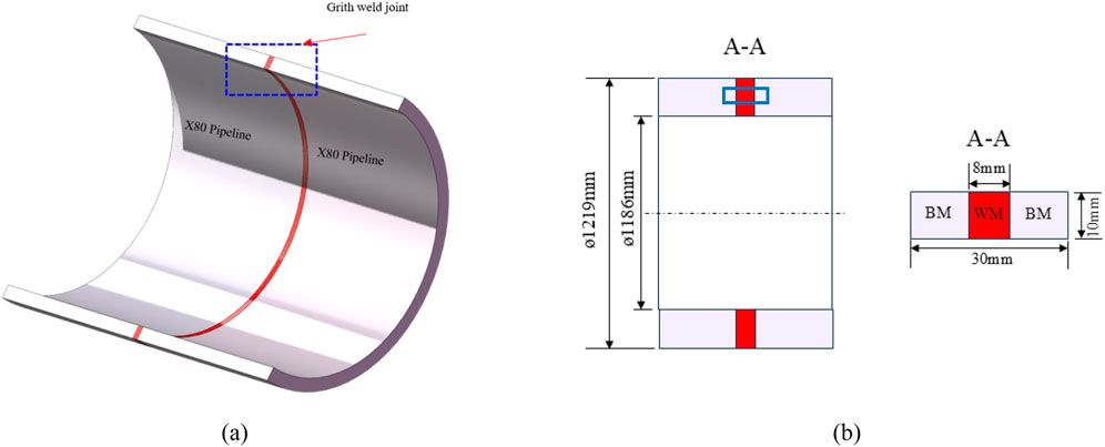
Figure 1. Structure of the X80 pipeline steel welded joint. (a) X80 pipeline steel welded joint (b) Material regions of the welded joint.
The chemical composition of the WM, expressed in weight percent, is listed in Table 1, serving to reveal the potential influence of alloying elements on mechanical performance and hydrogen sensitivity. All specimens were extracted along the axial direction of the pipe and sectioned perpendicular to the circumferential weld to ensure the weld region was centered within each sample. This configuration facilitates a systematic analysis of the microstructural and mechanical differences among the base metal (BM), HAZ, and WM under hydrogen exposure, thereby providing a reliable basis for subsequent mechanical characterization and hydrogen embrittlement assessment.
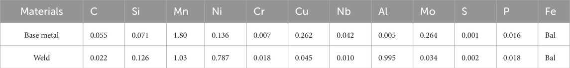
Table 1. Compositions of X80 steel base metal and weld (mass fraction/%).
2.2 Metallographic analysis
Welded joint specimens were extracted from the weld region of the pipeline steel. Surface preparation was carried out using an automated grinding and polishing machine, with final polishing down to 0.2 μm to minimize measurement error. The grinding/polishing wheel was operated at a rotational speed of 1,000 r/min. To remove surface oxides, 200-grit abrasive paper was used initially, followed by sequential fine grinding with 400-, 800-, and 1200-grit papers. Mirror polishing was completed using a polishing cloth and diamond suspension to ensure high surface quality and testing consistency. The specimen preparation process is illustrated in Figure 2.
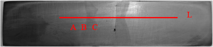
Figure 2. Locations for microstructural observation (A to C) and microhardness measurement (along line L).
After polishing, the weld cross-section was etched using a 4 wt% nitric acid–ethanol solution. Following etching, the samples were rinsed, dried, and subjected to microstructural examination using an optical microscope (OM). Representative micrographs were obtained from positions “A” to “C” as indicated in Figure 2.
2.3 Local mechanical tests
To evaluate the local mechanical properties across different regions of the X80 welded joint, miniature flat tensile specimens were fabricated from the joint cross-section using electrical discharge machining (EDM), as shown in Figure 3. Each specimen had a thickness of 2 mm, a width of 3 mm, and a gauge length of 20 mm.
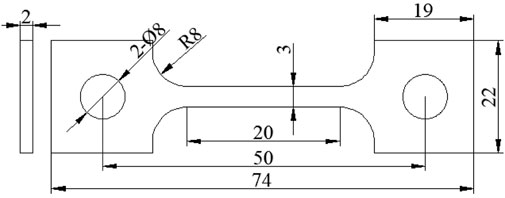
Figure 3. Dimensions of flat tensile specimens for local mechanical testing.
Specimens were extracted from the base metal (No. 1), HAZ (No. 2), and WM (No. 3), with the loading direction parallel to the weld interface to simulate the actual service stress orientation. The specimen layout and numbering are shown in Figure 4. This configuration was designed based on microstructural continuity and stress gradient considerations to reveal the transition in mechanical properties and provide input parameters for subsequent finite element modeling and hydrogen-induced cracking analysis.
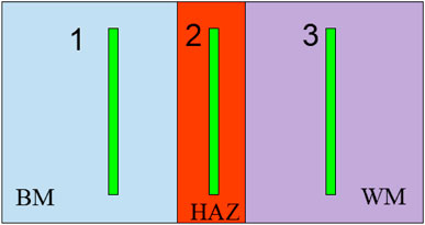
Figure 4. Positions of the three flat tensile specimens in the X80 welded joint.
During uniaxial tensile testing, specimen deformation was monitored in real time using a high-precision static strain measurement system with a range of ±65,000 με, resolution of 0.2 με, and measurement error within ±2 με or 0.4% of the reading, ensuring accurate data acquisition at small strain levels. All miniature tensile tests were conducted on a hydraulic servo loading system with a ±60 kN rated load, maximum operating pressure of 22 MPa, and flow rate of 28 L/min, providing stable loading and fine control suitable for small metallic specimens.
Engineering stress–strain curves from each region were obtained to characterize the local mechanical behavior of the welded joint. For subsequent finite element modeling, experimental data were converted to true stress and true strain using Equations 1 and 2 to better capture material response at large strains.
2.4 Microhardness testing
To characterize hardness distribution across different regions of the welded joint, systematic hardness measurements were conducted following the GB/T 2654—2008 “Welded Joint Hardness Testing Method” and GB/T 4340—2009 “Metal Vickers Hardness Test” standards. A micro-Vickers hardness tester equipped with an automatic turret and image recognition system was used to enable intelligent control and high-precision readings throughout the testing process. Prior to testing, specimen surfaces were mechanically ground and mirror-polished to remove oxides and surface defects. Hardness measurements covered the base metal, HAZ, and WM regions. All tests utilized an automatic loading/unloading program with a load of 196 gf (approximately 200 g) and a dwell time of 15 s. The image system identified the indentation morphology and calculated diagonal lengths to determine hardness values.
Indentation points were arranged along the cross-section with a spacing of 0.5 mm, allowing high-resolution mapping of hardness gradients across different zones.
3 Finite element simulation
3.1 USDFLD subroutine and crack propagation theory
3.1.1 USDFLD subroutine
In this study, material properties (such as stress, strain, and strain rate) are defined as functions of field variables
Initially, material mechanical characteristics are associated with the field variables. During the subroutine initialization, the program obtains the coordinates
3.1.2 Crack propagation based on crack-tip opening stress
To simulate the non-steady-state propagation of HIC under the coupled effects of high-pressure hydrogen environment and mechanical loading, this study develops a crack growth criterion based on Crack-Tip Opening Stress (CTOS), implemented in the ABAQUS finite element platform via the user subroutines USDFLD. The method assumes that hydrogen accumulates at the crack tip, weakening metallic bonds, making the normal principal stress the dominant driving force for crack growth. In this study, the critical opening stress (
Within each loading increment, the Cauchy stress tensor σ at the integration point is extracted using GETVRM and projected onto the unit normal vector n of the crack plane to calculate the opening stress as:
This expression represents the tensile normal stress perpendicular to the crack plane, reflecting the local opening stress at the crack tip. The computed
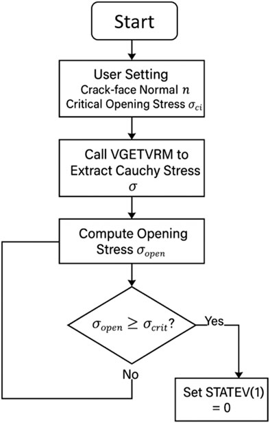
Figure 5. USDFLD flow.
This model preserves the mechanically dominated characteristics based on opening stress and is well suited for simulating dynamic hydrogen-induced crack propagation in heterogeneous structures such as dissimilar metal welded joints. Combined with the crack-tip submodel technique, it accurately captures crack-tip stress evolution and microscale damage behavior while maintaining computational efficiency.
3.2 Geometry and crack locations
The simplified schematic of the X80 pipeline steel welded joint used in the finite element simulations is shown in Figure 6. In actual engineering practice, the weld interface typically exhibits geometric curvature and a metallurgical diffusion zone rather than an ideal flat boundary. To reduce modeling complexity, the weld region is simplified with a perfectly planar interface in this study. To analyze the influence of mechanical gradients at the heterogeneous joint on the evolution of crack-tip stress–strain fields and to investigate local failure mechanisms at the interface, multiple initial cracks were introduced at the interface and its adjacent regions.
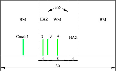
Figure 6. Schematic diagram of different regions in the X80 pipeline steel welded joint.
Near the weld interface, initial crack locations were sequentially arranged within the X80 BM, HAZ, BM/HAZ boundary, and the WM center. As illustrated in Figure 6, the y-axis is defined as the spatial coordinate normal to the interface, with y representing the crack positioned at the interface center.
Based on the USDFLD subroutine that implements a continuous spatial distribution of material properties, four representative initial crack paths were selected to reflect the impact of interface heterogeneity on crack propagation behavior. The crack locations are detailed in Figure 6 and summarized in Table 2.
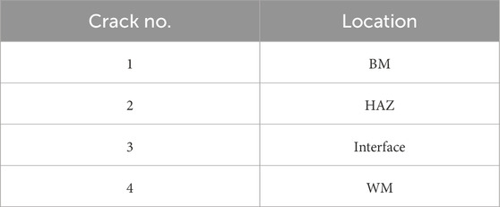
Table 2. Locations of four initial cracks in the weld interface region of X80 pipeline steel.
3.3 Mesh and boundary conditions
To investigate the influence of mechanical heterogeneity on crack-tip fields, a two-dimensional finite element model was established, consisting of: (i) crack-tip stress–strain field analysis, and (ii) crack propagation path simulation.
For the crack-tip field analysis, an initial crack length of a = 3.0 mm was set. The crack tip was modeled using collapsed quadrilateral elements with a midpoint node parameter of 0.25. The mesh near the crack tip region (r = 0.2 mm) was refined to an element size of 0.0025 mm, employing four-node plane strain elements (CPE4), as shown in Figure 7a.
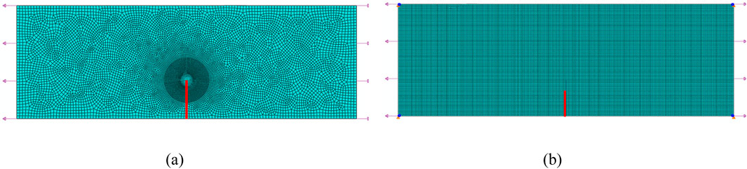
Figure 7. Mesh model: (a) Crack-tip stress–strain field analysis; (b) Crack propagation mesh model.
Crack propagation was simulated using a custom user field subroutine (USDFLD), which dynamically updates local material mechanical properties in the finite element model, enabling continuous evolution of properties near the crack tip and simulation of crack path growth. A constant stress intensity factor
4 Results and discussion
4.1 Microstructure of the X80 pipeline steel welded joint
Figure 8a shows that the X80 base metal primarily consists of regularly arranged polygonal ferrite and fine granular bainite. The ordered distribution of ferrite imparts good toughness and ductility to the material, while the fine particulate bainite exhibits strong corrosion resistance.
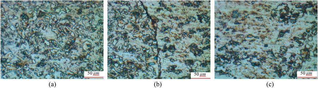
Figure 8. Microstructures of the X80 pipeline steel welded joint at different locations: (a) BM; (b) HAZ/WM interface; (c) Weld center.
Figure 8b illustrates the microstructural changes in the HAZ and at the weld interface. Due to the high heat input during welding and the fusion of different materials, significant microstructural transformations occur in this region, including the partial conversion of ferrite into columnar grains. The elongated morphology and larger size of these columnar grains create a weak zone at the weld edge, which is prone to crack initiation and often serves as the actual fracture origin.
Figure 8c depicts the microstructure at the weld center. Temperature gradients and cooling rate variations during welding lead to partial grain coarsening, while rapid cooling inhibits recrystallization and grain refinement, resulting in heterogeneous grain size distribution. These microstructural differences across regions significantly influence the local mechanical properties of the welded joint.
4.2 Local mechanical properties of the X80 welded joint
Miniature flat tensile specimens were extracted from the BM, HAZ, and WM of the X80 welded joint to measure local mechanical properties. Figure 9a shows the engineering stress–strain curves for BM, HAZ, and WM. Using Equations 1 and 2, the true stress–strain curves for the local regions of the X80 welded joint were obtained, as presented in Figure 9b. The stress-strain curve fitting equations for WM, HAZ, and BM are shown in Equation 4
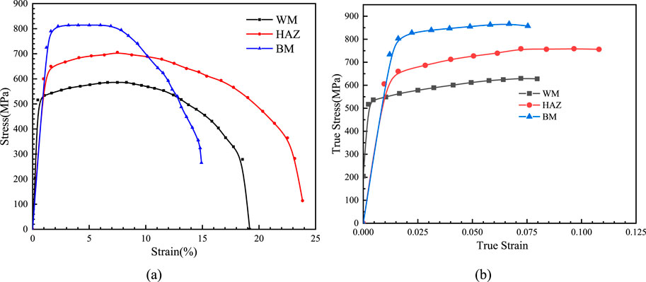
Figure 9. Stress–strain curves of the X80 welded joint (a) Engineering stress–strain curves and (b) True stress–strain.
The mechanical properties of the X80 pipeline steel welded joint were preliminarily evaluated by Vickers hardness testing, with the hardness distribution shown in Figure 10. The results indicate that thermal cycling during welding reduces dislocation density and causes precipitate coarsening, leading to softening in the critical and fine-grained zones, exhibiting a typical “V”-shaped hardness profile. The BM, relatively unaffected by heat input, maintains a high hardness level of approximately 296 ± 2 HV. In contrast, the HAZ shows significant hardness reduction, averaging 209 ± 5 HV, reflecting grain coarsening and thermal softening. The WM hardness gradually increases from 208 HV to about 287 HV, indicating its distinct microstructural state. The high hardness of the X80 BM and the softening in the HAZ highlight the critical roles of material composition, heat input, and strength matching in influencing softening degree. A pronounced hardness gradient exists between the WM and HAZ, and such mechanical heterogeneity can more readily induce HIC under high-pressure hydrogen environments, making the interface region a sensitive site for crack initiation and propagation.
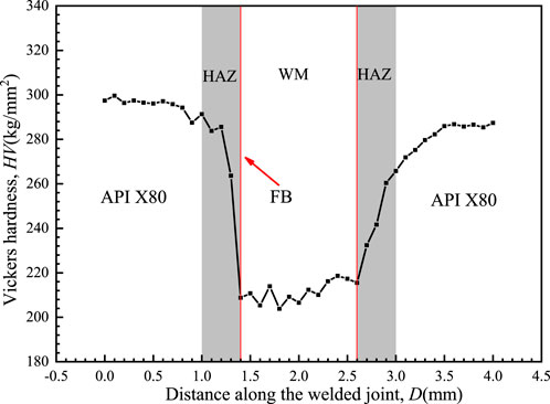
Figure 10. Hardness distribution along the X80 pipeline steel welded joint.
The international standard ISO 15653:2018 provides a technical basis for evaluating the mechanical properties of different regions within welded joints (ISO 15653:2018, 2018). The conversion relationships between hardness and mechanical properties established by this standard enable a relatively accurate estimation of the mechanical property distribution in both the BM and the WM (Wang et al., 2025b). This approach has been widely applied to various engineering materials, including alloy steels, nickel-based alloys, and stainless steels. The correlations between hardness and strength are presented in Equations 5 and 6. The distributions of yield strength and tensile strength along the X80 pipeline steel welded joint are shown in Figures 11a,b.
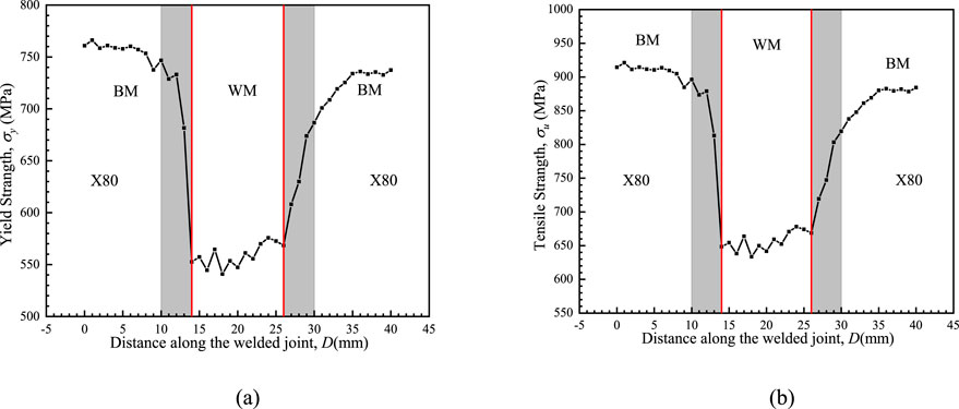
Figure 11. Strength distribution of the X80 pipeline steel welded joint: (a) Yield strength; (b) Tensile strength.
Based on these hardness-strength conversion relations, the strength distribution at various locations in the X80 welded joint was calculated. By substituting the local yield strength into Equation 1, the corresponding stress–strain curve at each point was obtained. Subsequently, these location-dependent stress–strain data were assigned to the finite element model via the USDFLD subroutine, enabling a continuous spatial mapping of mechanical properties throughout the welded joint.
4.3 Crack-tip mechanical fields at different locations of the welded joint
Figure 12 presents the distribution of von Mises stress at the crack tips located in different regions of the welded joint. Cracks 1 and 4 are situated within the BM and weld center, respectively, where material properties are relatively homogeneous. The crack-tip stress fields exhibit symmetrical distributions, with maximum von Mises stresses of approximately 885 MPa and 700 MPa, respectively (see Figures 12a,d).
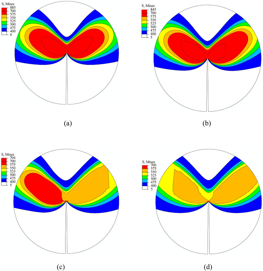
Figure 12. Distribution of crack-tip stress fields at different locations. (a) BM (b) HAZ (c) Interface (d) WM.
Crack 2 is located in the HAZ, where the maximum crack-tip stress reaches about 845 MPa. Due to the gradual transition of material properties on both sides of the crack, the stress field shows only slight asymmetry (Figure 12b).
In contrast, Crack 3 is positioned at the BM/WM interface, where significant mechanical property differences exist across the crack flanks, resulting in a markedly asymmetric crack-tip stress distribution (Figure 12c). This observation indicates that material heterogeneity at the weld interface strongly influences the local crack-tip stress state, suggesting this region as a preferential site for hydrogen-induced crack initiation and growth (Wang et al., 2024c).
The distribution of equivalent plastic strain at the crack tip reflects the differences in mechanical properties and corresponding deformation characteristics across various regions of the welded joint, as shown in Figure 13. Crack 1, located in the BM region with relatively high yield strength, exhibits low plastic strain at the crack tip (maximum approximately 0.175), indicating low deformation concentration, stable crack propagation, and good resistance to plastic deformation, resulting in lower sensitivity to HIC. In contrast, Crack 2 in the HAZ shows slightly increased local plastic strain (maximum around 0.185) due to welding-induced thermal softening, despite good material continuity. The expanded plastic zone makes this region more susceptible to microdamage, thereby increasing the risk of HIC. Crack 3, positioned at the BM/WM interface where significant mechanical property gradients exist, exhibits the highest maximum plastic strain of 0.292. The pronounced plastic strain localization reflects severe softening and enhanced local deformation capacity at the interface, leading to plastic damage accumulation and marking this region as the most sensitive to HIC within the joint. Crack 4, located at the weld center, despite relatively uniform microstructure, shows lower strength and a maximum plastic strain of 0.283, indicating strong local plastic deformation capacity and a similarly high risk of HIC. Overall, the plastic strain distribution within the joint negatively correlates with material strength, and the high plastic deformation in softened regions is a key factor promoting preferential hydrogen-induced crack initiation and propagation.
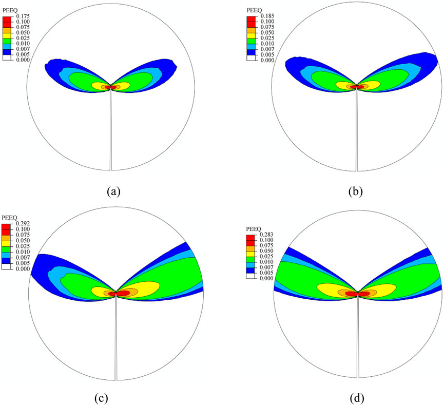
Figure 13. Distribution of crack-tip strain fields at different locations. (a) BM (b) HAZ (c) Interface (d) WM.
The spatial variation of mechanical properties significantly influences the distribution of crack-tip mechanical fields, and heterogeneous mechanical responses can cause deviation in crack propagation paths. Under stable operating conditions, crack growth is primarily governed by the crack-tip opening stress. Considering that HIC typically occurs under constant or slowly varying loads, this study infers from the stress field evolution that cracks tend to propagate toward regions with higher yield strength.
To verify this hypothesis, the next section will present crack propagation path simulations for different initial cracks within the welded joint based on the USDFLD subroutine, aiming to thoroughly analyze crack deflection behavior and potential failure modes in heterogeneous structures.
4.4 Crack propagation paths at different locations of the welded joint
HIC is a delayed fracture phenomenon occurring in metallic materials under sustained tensile stress combined with high-pressure hydrogen environments. The constant external load and the localized stress field at the crack tip are the primary driving forces for HIC propagation. Under continuous stress, stress concentration in defect regions such as microcracks or heterogeneous microstructures may initiate crack nucleation and unstable growth. This section analyzes the influence mechanism of mechanical heterogeneity on HIC crack propagation paths from a mechanical perspective.
Based on crack location analysis, HIC cracks generally tend to propagate toward regions with higher yield strength. This is because high-strength areas exhibit lower toughness and reduced plastic dissipation capacity at the crack tip, thereby decreasing resistance to crack growth. Conversely, low-strength regions possess greater ductility and plasticity, which can partially relieve crack-tip stress concentration and enhance resistance to crack propagation. The crack propagation paths are shown in Figure 14. These findings highlight that gradients in material strength distribution are key factors influencing the deflection of hydrogen-induced crack paths.
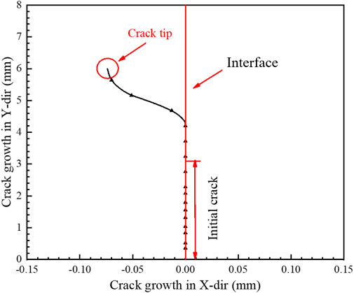
Figure 14. Crack propagation path and crack growth length at the DMWJ interface.
4.5 Evolution of mechanical fields at the growing crack tip
In this section, a finite element model based on ABAQUS was developed to simulate crack propagation behavior at the weld interface region under constant load. The evolution of crack-tip mechanical fields during crack growth was analyzed by extracting von Mises stress and equivalent plastic strain (PEEQ) distributions at crack extensions of 200 μm, 400 μm, and 600 μm, as shown in Figure 15.
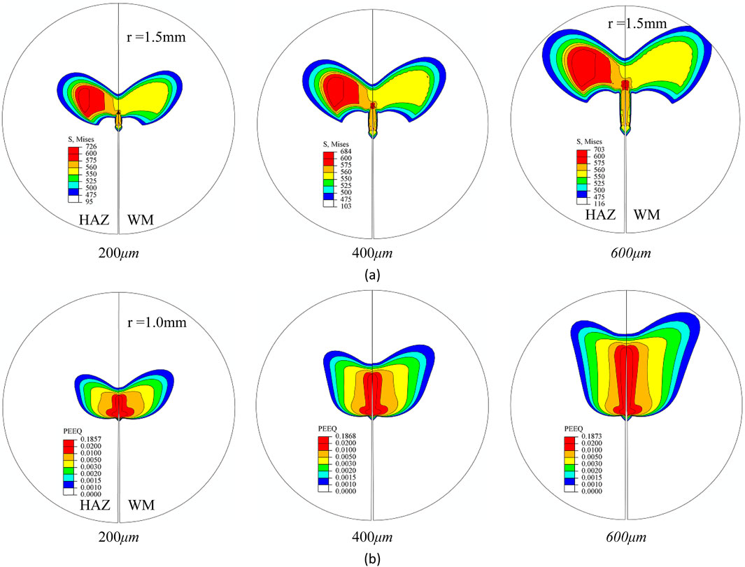
Figure 15. Mechanical fields at the growing crack tip near the weld interface: (a) Crack-tip von Mises stress; (b) Crack-tip equivalent plastic strain.
The results indicate significant changes in the stress and strain states near the crack tip as the crack advances. The mechanical field characteristics at the newly formed crack tip differ notably from those of the initial stationary crack. This variation mainly arises from local unloading ahead of the crack front during propagation, which releases and redistributes the original stress concentration, accompanied by a concurrent adjustment in the plastic zone size. Further observation of Figure 15 reveals pronounced residual stress and plastic strain retention zones along the crack growth path. A local reloading zone forms near the new crack tip, while the crack wake retains a “plasticity memory zone” accumulated during previous growth stages. Although PEEQ values in the wake are slightly lower than those near the new tip, they remain elevated, indicating clear “transferability” and “history dependence” of the crack-tip response. Moreover, the mechanical field reconstruction induced by crack growth is mainly confined to the high-strain near-tip region, while stress states farther from the crack front remain essentially stable. This suggests that the propagation-induced disturbance to the overall stress distribution is localized.
In summary, under constant loading, crack growth triggers a localized mechanical field evolution centered on the crack-tip plastic zone, exhibiting spatial continuity and deformation inheritance. This plasticity-dominated evolution mechanism provides fundamental mechanical support for stable HIC propagation under non-instantaneous loading conditions. Although hydrogen diffusion and environmental corrosion effects are not explicitly considered here, the observed crack-tip evolution trends offer valuable insights into the driving mechanisms of HIC.
5 Conclusion
This study systematically analyzed and characterized the microstructure and local mechanical properties of X80 pipeline steel welded joints. A user-defined subroutine (USDFLD) was implemented to realize the continuous assignment of material properties within the finite element model, capturing mechanical heterogeneity. Crack propagation paths under HIC conditions were also investigated. The main conclusions are as follows.
1) The X80 BM primarily consists of polygonal ferrite and bainite. The HAZ exhibits significant recrystallization with increased and randomly distributed grain sizes. The weld center shows pronounced grain coarsening due to temperature gradients and cooling rate differences. Microstructural variations among different joint regions are the fundamental cause of spatial mechanical heterogeneity.
2) The welded joint exhibits a typical “V”-shaped hardness profile, with the highest hardness in the BM (∼296 HV) and a marked decrease to around 209 HV in the HAZ. The overall hardness difference exceeds 80 HV, indicating a significant strength gradient. The hardness jump at the interface creates a pronounced stress concentration zone, making it a potential sensitive site for preferential HIC initiation.
3) Material property heterogeneity strongly affects the distribution of stress and plastic strain at the crack tip. The high-strength side tends to develop stress concentrations, while the low-strength side undergoes larger plastic deformation. The interface region, combining stress peaks and plastic strain localization, is identified as the most HIC-sensitive and weakest area in the welded joint.
4) Crack propagation paths generally tend to deviate toward regions with higher yield strength. These areas possess lower toughness and are less capable of alleviating crack-tip stress concentration, thereby reducing fracture resistance. Conversely, low-strength regions dissipate stress through plasticity mechanisms, enhancing resistance to crack growth and inhibiting HIC.
5) During crack propagation, the crack-tip von Mises stress and equivalent plastic strain undergo significant evolution. Local unloading at the advancing crack tip leads to stress and plastic zone reconfiguration, forming residual stress and “plasticity memory” zones along the crack path. The influence of crack growth is mainly confined to the near-tip region, with limited impact on the far-field mechanical state, indicating a localized effect of crack extension.
Data availability statement
The original contributions presented in the study are included in the article/supplementary material, further inquiries can be directed to the corresponding author.
Author contributions
YJ: Data curation, Investigation, Methodology, Validation, Writing – original draft, Writing – review and editing. HX: Investigation, Methodology, Project administration, Resources, Writing – review and editing. ZW: Formal Analysis, Funding acquisition, Methodology, Validation, Writing – review and editing.
Funding
The author(s) declare that financial support was received for the research and/or publication of this article. Shaanxi Provincial Natural Science Basic Research Program (2025JC-YBMS-542), Key Scientific Research Program of Shaanxi Provincial Department of Education (24JR048), Xianyang Innovation Capability Support Program - Excellent Innovation Team Program (L2024-CXNLKJRCTD-KJTD-0009) and Scientific Research Projects of Shaanxi Energy Institute (2024KYTD05).
Conflict of interest
The authors declare that the research was conducted in the absence of any commercial or financial relationships that could be construed as a potential conflict of interest.
Generative AI statement
The author(s) declare that no Generative AI was used in the creation of this manuscript.
Publisher’s note
All claims expressed in this article are solely those of the authors and do not necessarily represent those of their affiliated organizations, or those of the publisher, the editors and the reviewers. Any product that may be evaluated in this article, or claim that may be made by its manufacturer, is not guaranteed or endorsed by the publisher.
References
Ayrault, D., Bonaventure, A., Asserin, O., Montay, G., and Klosek, V. (2011). Numerical and experimental evaluation of residual stresses in dissimilar weld joints. Pressure Vessels and Piping Conference 44564, 1515–1522.
Benjamin, A. C., Freire, J. L. F., Vieira, R. D., and Cunha, D. J. (2016). Interaction of corrosion defects in pipelines–part 2: MTI JIP database of corroded pipe tests. Int. J. Press. Vessels Pip. 145, 41–59. doi:10.1016/j.ijpvp.2016.06.006
Betegón, C., and Peñuelas, I. (2006). A constraint based parameter for quantifying the crack tip stress fields in welded joints. Eng. Fract. Mech. 73 (13), 1865–1877. doi:10.1016/j.engfracmech.2006.02.012
Burstow, M. C., Howard, I. C., and Ainsworth, R. A. (1998). The influence of constraint on crack tip stress fields in strength mismatched welded joints. J. Mech. Phys. Solids 46 (5), 845–872. doi:10.1016/s0022-5096(97)00098-7
Dong, L., Peng, Q., Han, E. H., Ke, W., and Wang, L. (2018). Microstructure and intergranular stress corrosion cracking susceptibility of a SA508-52M-316L dissimilar metal weld joint in primary water. J. Mater. Sci. and Technol. 34 (8), 1281–1292. doi:10.1016/j.jmst.2017.11.051
ISO 15653:2018 (2018). Metallic materials – method of test for the determination of quasistatic fracture toughness of welds. Geneva, Switzerland: International Organization for Standardization
Kim, C. M., Lee, J. B., and Yoo, J. Y. (2005). A study on the metallurgical and mechanical characteristics of the weld joint of X80 steel. In: ISOPE international ocean and polar engineering conference; 2005 June 19-24; Seoul, Korea. Tampa, FL: ISOPE.
Li, X., Zhang, Y., Abbassi, R., Yang, M., Zhang, R., and Chen, G. (2021). Dynamic probability assessment of urban natural gas pipeline accidents considering integrated external activities. J. Loss Prev. Process Industries 69, 104388. doi:10.1016/j.jlp.2020.104388
Peng, Q. J., Xue, H., Hou, J., Sakaguchi, K., Takeda, Y., Kuniya, J., et al. (2011). Role of water chemistry and microstructure in stress corrosion cracking in the fusion boundary region of an alloy 182-A533B low alloy steel dissimilar weld joint in high temperature water. Corros. Sci. 53 (12), 4309–4317. doi:10.1016/j.corsci.2011.08.046
Shoji, T., Lu, Z., and Murakami, H. (2010). Formulating stress corrosion cracking growth rates by combination of crack tip mechanics and crack tip oxidation kinetics. Corros. Sci. 52 (3), 769–779. doi:10.1016/j.corsci.2009.10.041
Štefane, P., Naib, S., Hertelé, S., De Waele, W., and Gubeljak, N. (2019). Crack tip constraint analysis in welded joints with pronounced strength and toughness heterogeneity. Theor. Appl. Fract. Mech. 103, 102293. doi:10.1016/j.tafmec.2019.102293
Sun, J., and Cheng, Y. F. (2018). Assessment by finite element modeling of the interaction of multiple corrosion defects and the effect on failure pressure of corroded pipelines. Eng. Struct. 165, 278–286. doi:10.1016/j.engstruct.2018.03.040
Wang, Z., Xue, H., Wang, S., and Zhang, Y. (2023). A multi-method coupled approach to simulate crack growth path and stress-strain field at the tip of the growing crack in the dissimilar metal welded joint. Int. J. Press. Vessels Pip. 206, 105046. doi:10.1016/j.ijpvp.2023.105046
Wang, Z., Xue, Y., Wang, R., Wu, J., Zhang, Y., and Xue, H. (2024a). Review on crack growth driving force at the tip of stress corrosion cracking in the safe end dissimilar metal welded joint. Nucl. Eng. Des. 429, 113609. doi:10.1016/j.nucengdes.2024.113609
Wang, Z., Xue, H., Zhang, Y., Wang, R., and Geng, M. (2024b). Characterization of mechanical heterogeneity and study of the mechanical field at the tip of the stationary-growing crack in dissimilar metal welded joints. J. Eng. Mater. Technol. 146 (4), 041003. doi:10.1115/1.4065096
Wang, Z., Xue, H., Wang, R. X., Wu, J., and Wu, Z. (2024c). Study on microstructure, SCC crack propagation paths, and mechanical field at the tip of the stationary-propagating crack of pipeline steel girth welded joint. J. Press. Vessel Technol., 1–28. doi:10.1115/1.4067926
Wang, Z., Xue, H., Hui, Y., Wang, R., Wu, J., and Zhang, Y. (2025a). Investigation of crack propagation and mechanical field evolution at the tip of a growing crack under variable loading in dissimilar metal welded joints. Int. J. Press. Vessels Pip. 216, 105496. doi:10.1016/j.ijpvp.2025.105496
Wang, Z., Xue, H., Wang, R., and Zhang, Y. (2025b). Effect of microstructure and mechanical heterogeneity on mechanical fields at stationary and growing crack tips in dissimilar metal welded joints. Adv. Eng. Mater. 27 (10), 2402868. doi:10.1002/adem.202402868
Xie, G. M., Duan, R. H., Xue, P., Ma, Z. Y., Liu, H. L., and Luo, Z. A. (2020). Microstructure and mechanical properties of X80 pipeline steel joints by friction stir welding under various cooling conditions. Acta Metall. Sin. Engl. Lett. 33 (1), 88–102. doi:10.1007/s40195-019-00940-0
Xu, K., Qiao, G., Pan, X., Chen, X. w., Liao, B., and Xiao, F. r. (2020). Simulation of fatigue properties for the weld joint of the X80 weld pipe before and after removing the weld reinforcement. Int. J. Press. Vessels Pip. 187, 104164. doi:10.1016/j.ijpvp.2020.104164
Xue, H., Li, Z. J., Lu, P. Z., and Shoji, T. (2011). The effect of a single tensile overload on stress corrosion cracking growth of stainless steel in a light water reactor environment. Nucl. Eng. Des. 241 (3), 731–738. doi:10.1016/j.nucengdes.2010.12.025
Xue, H., Wang, Z., Wang, S., He, J., and Yang, H. (2021). Characterization of mechanical heterogeneity in dissimilar metal welded joints. Materials 14 (15), 4145. doi:10.3390/ma14154145
Xue, H., Wang, R., Wang, Z., Wu, J., and Hao, X. (2024). Study on crack growth path of API-5L X80 welded joints based on inhomogeneous mechanical properties. Structures 70, 107713. doi:10.1016/j.istruc.2024.107713
Yang, Y., Shi, L., Xu, Z., Lu, H., Chen, X., and Wang, X. (2015). Fracture toughness of the materials in welded joint of X80 pipeline steel. Eng. Fract. Mech. 148, 337–349. doi:10.1016/j.engfracmech.2015.07.061
Zhao, L., Yang, B., and Sun, Y. (2025). Crack-tip constraint analysis of the dissimilar metal-welded joint and constraint match with test specimens. Nucl. Sci. Eng. 199, 1512–1527. doi:10.1080/00295639.2025.2456369
Keywords: pipeline steel, welded joint, microstructure, hic, crack propagation
Citation: Jia Y, Xue H and Wang Z (2025) Research on hydrogen induced cracking behavior and service performance of metal pipeline material. Front. Mater. 12:1668151. doi: 10.3389/fmats.2025.1668151
Received: 17 July 2025; Accepted: 29 July 2025;
Published: 14 August 2025.
Edited by:
Yutai Su, Northwestern Polytechnical University, ChinaReviewed by:
Xujiang Chao, Northwestern Polytechnical University, ChinaKun Zhang, zhejiang university of technology, China
Copyright © 2025 Jia, Xue and Wang. This is an open-access article distributed under the terms of the Creative Commons Attribution License (CC BY). The use, distribution or reproduction in other forums is permitted, provided the original author(s) and the copyright owner(s) are credited and that the original publication in this journal is cited, in accordance with accepted academic practice. No use, distribution or reproduction is permitted which does not comply with these terms.
*Correspondence: Zheng Wang, emhrc3lqeTUxOUAxNjMuY29t