 Litao Shen1,2
 Tianhui Zhang
- 1Shanxi Transportation Technology Research & Development Co., Ltd., Taiyuan, China
- 2Shanxi Transportation Research Institute Group Co., Ltd., Taiyuan, China
- 3College of Aeronautics and Astronautics, Taiyuan University of Technology, Taiyuan, China
The dynamic response of ultra-high-performance concrete (UHPC) hollow beams under drop-weight impact loading was investigated through a combined experimental and numerical simulation. High-speed cameras were utilized to record the dynamic response process of the UHPC hollow beams. The structural response process was categorized into four distinct phases: the initial peak loading phase, the steel fiber pull-out phase, the unloading phase, and the structural stabilization phase. A finite-element model developed in ABAQUS/Explicit accurately reproduced the experimental results and was employed to elucidate deformation and failure mechanisms. Further parametric studies revealed that the peak impact load increases with the height-to-width ratio under constant structural thickness. Beams with a height-to-width ratio of 1.4 exhibited stable post-peak load-bearing behavior. Moreover, for a fixed height-to-width ratio, configurations with greater thickness along the height and reduced thickness along the width demonstrated enhanced impact resistance. These findings provide valuable insights for the design of impact-resistant UHPC structures, highlighting the importance of geometric optimization to improve performance under dynamic loading conditions.
1 Introduction
Ultra-high-performance concrete (UHPC) is a high-toughness cementitious composite material composed of cement, mineral admixtures, aggregates, fibers, chemical additives, and water. It exhibits ultra-high mechanical properties and exceptional impermeability and has been widely applied in the construction industry (Bajaber and Hakeem, 2021; Tayeh et al., 2019; Xue et al., 2020).
Modern infrastructure predominantly utilizes concrete as the base material. Structural components such as beams, columns, and piers may experience varying levels of impact loads, including collisions between vehicles and bridge barriers, highway guardrails, or ships and bridge piers (Zhou et al., 2018). Localized damage caused by impact loads can propagate throughout the structure, leading to a loss in its original load-bearing capacity (Jia et al., 2021). Fan et al. (2019) conducted drop-weight tests on three types of UHPC columns with different nesting configurations, revealing that UHPC nested at the impact location and column ends exhibited the poorest impact resistance. Wei et al. (2019) performed drop-weight impact tests on square and circular UHPC and normal-strength concrete (NSC) columns, proposing a theoretical method to evaluate the residual load-bearing capacity of UHPC columns post-impact. Wu et al. (2019), Wang et al. (2019a), and Wang et al. (2019b) systematically investigated the dynamic responses of UHPC-filled steel tubes under varying boundary conditions, impact energies, and steel tube thicknesses. Their results demonstrated that adjusting the impact energy and the ratio of outer-to-inner steel tube thickness significantly enhanced structural impact resistance.
In recent years, researchers worldwide have extensively studied the response mechanisms and energy dissipation of UHPC-based materials and structures under dynamic loading (Li et al., 2015; Yan et al., 2022; Astarlioglu and Krauthammer, 2014). Jia et al. (2021) experimentally and numerically analyzed the low-velocity impact performance of reinforced UHPC members, proposing a parameter generation method for the UHPC continuous surface cap (CSC) model. This model was validated through drop-weight tests on reinforced UHPC specimens. Khosravani et al. (2019) employed a modified Hopkinson bar to analyze cylindrical UHPC specimens with different mix proportions under a strain rate of 30 s−1, determining their dynamic elastic modulus, tensile strength, and specific fracture energy. Fujikake et al. (2006) conducted drop-weight tests on simply supported I-shaped UHPC beams with 2.6% longitudinal reinforcement. Flexural distributed cracks were observed at the mid-span bottom of the beams, leading to the development of a two-degrees-of-freedom theoretical model. Yoo et al. (2015) and Yoo et al. (2016) investigated the impact resistance of fixed rectangular cross-section UHPC beams with varying reinforcement ratios and steel fiber types. Their findings indicated that increasing the reinforcement ratio and incorporating 2% straight steel fibers significantly improved impact resistance.
Existing studies on the dynamic response of UHPC structures have primarily focused on solid and composite configurations. Compared to solid UHPC or composite systems, hollow beams offer significant advantages in reducing self-weight and material usage while maintaining high mechanical performance, making them particularly suitable for applications where weight savings and sustainability are prioritized, such as long-span bridges, protective structures, and advanced prefabricated elements. The novelty of this work lies in the integrated experimental and numerical approach to systematically reveal the failure mechanisms and energy dissipation characteristics specific to hollow UHPC cross-sections under impact, which have not been adequately addressed in previous studies focused predominantly on solid or composite UHPC members. This research establishes the influence of key geometric parameters, such as height-to-width ratio and directional thickness distribution, on impact resistance, providing new insights for the optimized design of hollow UHPC structures under dynamic loads.
To address this gap, this study investigates the dynamic response of UHPC hollow beams subjected to impact loading. Drop-weight tests were conducted to evaluate the impact resistance and fracture mechanisms of UHPC hollow beams under varying impact velocities. High-speed cameras were employed to record structural dynamic responses. A finite-element model was developed using ABAQUS, and its reliability was validated by comparing simulated structural responses and impact force–time histories with experimental observations. Parametric analyses were performed to examine the influence of wall thickness and height-to-width ratio on the impact resistance of UHPC hollow beams under a constant cross-sectional area.
2 Experimental investigations
2.1 Specimens and experimental setup
The dynamic impact tests on UHPC hollow beams were conducted using a DHR9401 self-weight drop-weight impact testing platform, as illustrated in Figure 1. The support blocks were placed horizontally on the testing platform, and the specimen was positioned on top of the support blocks under its own weight, with no additional constraints between the specimen and the supports. The specimen had a total length of 550 mm, a width and height of 150 mm, and a wall thickness of 30 mm. The contact length between the specimen and the support blocks was 25 mm, resulting in an effective specimen length of 500 mm. The drop hammer, made of 64 HRC chromium steel with a diameter of 80 mm, was equipped with a sensor at its tip to record the impact force–time history during the test using an oscilloscope. A high-speed digital image correlation (DIC) camera was placed in front of the specimen to capture the deformation process after impact. The i-SPEED 7 high-speed camera, manufactured by the UK-based company iX-Cameras, was connected to a computer via i-SPEED software. During testing, two cameras were triggered simultaneously with the dynamic strain gauge and the impact hammer. Finally, the captured dynamic response signals were processed using a typical transfer path analysis method to generate a cloud diagram and time–history curves of the calibrated impact area on the specimen.
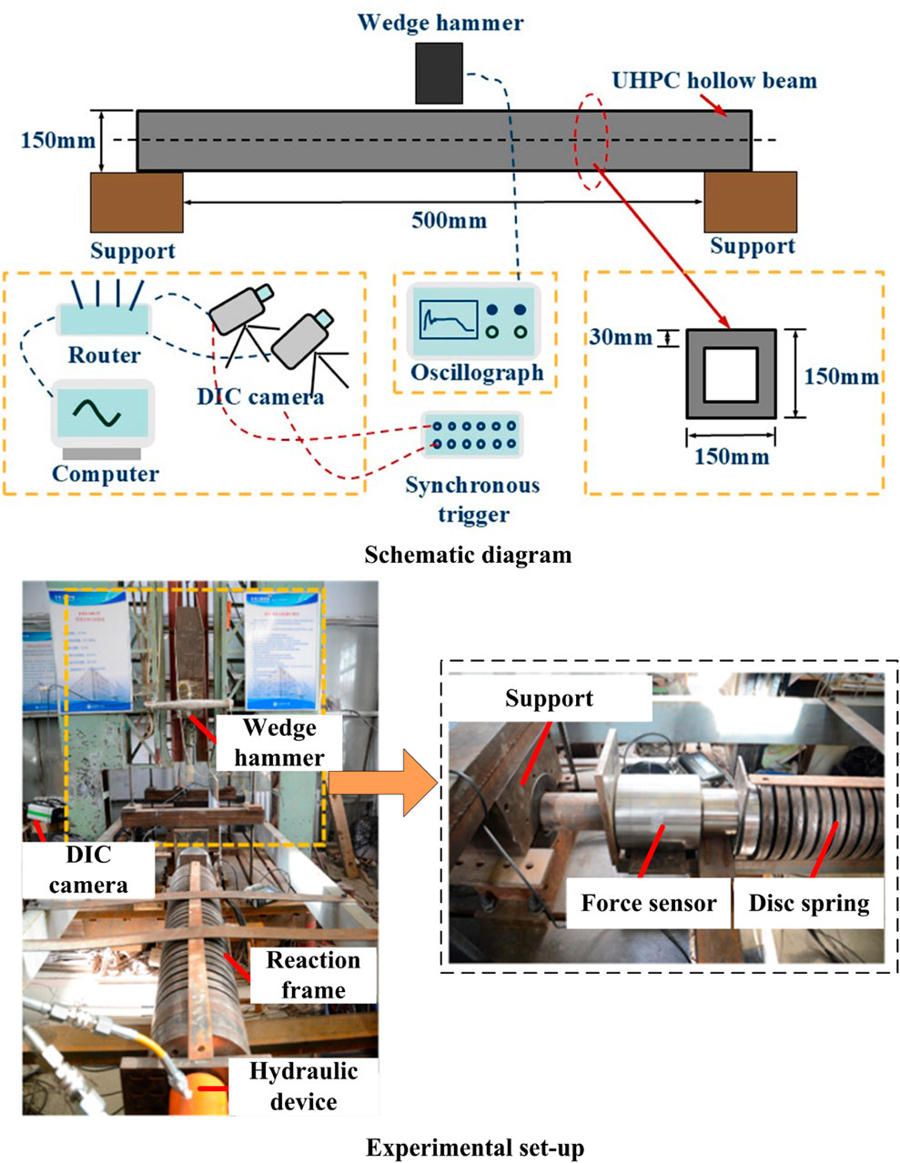
Figure 1. Experimental setup of drop-weight test.
Gan et al. (2024) summarized the distribution of dynamic strain rates in concrete under impact, seismic, and blast loading, as well as the achievable strain-rate ranges of different testing apparatuses. The dynamic strain rates induced by accidental loads during the service life of concrete structures generally do not exceed 10−1 s−1. Based on the practical service conditions of concrete structures, impact tests were conducted using a wedge hammer with a mass of 0.52 kg and an additional counterweight of 30 kg, released from heights of 0.1 m and 1 m, respectively.
The UHPC hollow beams were fabricated using the following raw materials: cement, mineral powder, silica fume, calcium powder, coarse sand, medium sand, fine sand, water reducer, defoamer, expansion agent, water, and copper-coated steel fibers. The specific mix proportions were as follows: cement (850 kg/m3), mineral powder (50 kg/m3), silica fume (50 kg/m3), calcium powder (50 kg/m3), coarse sand (590 kg/m3), medium sand (210 kg/m3), fine sand (200 kg/m3), water reducer (5 kg/m3), defoamer (2 kg/m3), expansion agent (0.16 kg/m3), water (185 kg/m3), and copper-coated steel fibers (1.5% by volume). Standard quasi-static tests confirmed that the UHPC material achieved a compressive strength of no less than 120 MPa and a tensile strength of no less than 7 MPa after 28 days of curing.
2.2 Experimental results
The dynamic impact test results of the UHPC hollow beams were categorized into two parts: quantitative results, which describe the variation of impact force with response time after the specimen was subjected to drop-weight impact, and qualitative results, which illustrate the typical deformation modes and overall dynamic response processes.
Figure 2 presents the impact force–time history curves of the UHPC hollow beams under drop-weight impacts at heights of 0.1 m and 1.0 m. Ten specimens were tested for each of the two impact loading conditions. The experimental data for each condition were represented by the average of force–time histories from at least three tests that showed high reproducibility. The structural response process under the drop height loading (Figure 3) was divided into four phases: Initial peak load phase: The impact force rapidly reached its peak. Steel fiber pull-out phase: The force fluctuated due to fiber bridging effects. Unloading phase: The force decayed as cracks propagated. Structural stabilization phase: The residual force stabilized after significant damage.
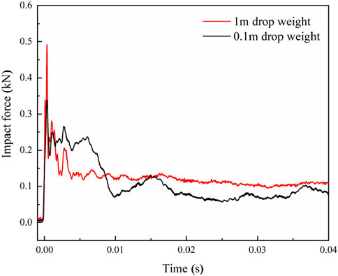
Figure 2. Impact force–time curve of a UHPC hollow beam under different impact velocities.
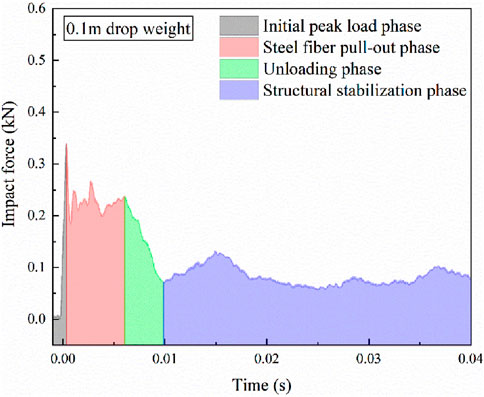
Figure 3. Response process analysis of a UHPC hollow beam.
During the initial loading phase, the UHPC hollow beam specimen undergoes elastic deformation. The interface between the fibers and the concrete matrix is the first to deteriorate, during which microcracks within the specimen initiate and propagate independently. As the response progresses, the bridging effect of the steel fibers across the concrete matrix results in a gradual decline in load-carrying capacity with increasing deflection. The debonding and slip between the steel fibers and the matrix cause minor fluctuations in the response curve. The failure of the interfacial zone induces stress concentration in the surrounding concrete matrix, accelerating crack propagation at the tips and leading to the failure of the concrete matrix. Dispersed microcracks continue to initiate and expand, eventually coalescing into macrocracks. Once macrocracks form, the dominant crack at the mid-span propagates rapidly, resulting in the failure of the specimen.
Under the 0.1 m drop height, the peak impact force was 0.34 kN. During the steel fiber pull-out phase, the force oscillated between 0.18 kN and 0.24 kN. Complete unloading occurred at 0.01 s, after which the force stabilized. For the 1.0 m drop height, the peak force increased to 0.49 kN, with oscillations between 0.13 kN and 0.28 kN. Structural failure occurred at 0.004 s, leading to a rapid decline in load-bearing capacity (Figure 2). Notably, higher impact energies shortened the response durations during the pull-out and unloading phases.
The UHPC hollow beams demonstrated distinct impact resistance characteristics under varying impact energies. The peak impact force increased with impact energy, while higher energy impacts also widened the fluctuation range during the pull-out phase. Compared to the 1.0 m drop height, the peak force at 0.1 m decreased by 26%. DIC images captured at critical time points (Figure 4) revealed the deformation process. 0.1 m impact: Cracks initiated at the bottom and propagated upward, but the specimen retained partial integrity after fiber pull-out. 1.0 m impact: Cracks rapidly extended from the bottom, causing complete fiber debonding and structural collapse at 0.004 s. The random distribution of steel fibers in the UHPC matrix led to non-uniform strain localization. For instance, under the 0.1 m impact, fracture locations deviated from the loading point due to fiber heterogeneity. The dynamic response process of the UHPC hollow beam observed in the experiment is similar to the responses reported by Fan et al. (2019) and Yoo et al. (2015). Under a drop height of 1 m, the UHPC hollow beam exhibited a flexural failure mode, while under a drop height of 0.1 m, it displayed a shear failure mode. The specimen was placed horizontally on the supports and was free to rotate at the boundaries when subjected to impact loading. As a result, no cracking occurred at the boundaries of the UHPC hollow beam under either impact condition. Post-processing of DIC data for the 1.0 m impact case (Figure 5) revealed strain (εxx, εyy) and stress (fxx, fyy) distributions at 0.004 s. The maximum tensile strain and stress occurred along the length direction, decreasing upward. Minor scattered strains in the height direction highlighted the influence of fiber randomness on localized deformation.
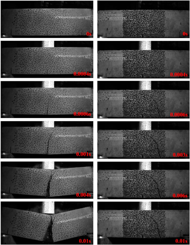
Figure 4. Response process of a UHPC hollow beam under different impact velocities.
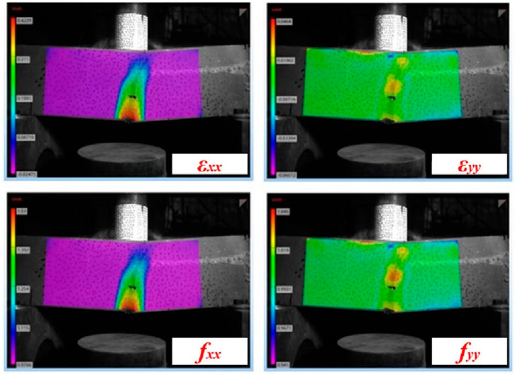
Figure 5. Strain and force analysis of a UHPC hollow beam at 0.004 s under impact load with a drop-weight height of 1 m.
As shown in Figures 2–4, the UHPC hollow beams exhibit distinct fracture failure modes under different impact loading conditions. For the given material and geometric parameters, the load-bearing capacity of the UHPC hollow beam increases with the applied impact energy. Under higher impact energy, the structure experiences complete failure and loses its load-carrying capacity. After the initial peak load is reached, the pull-out behavior of steel fibers contributes to a stable plateau stage in the structural response. Once the steel fibers are completely pulled out, the structure undergoes total failure. It is noteworthy that, as cracking develops, the load-bearing capacity of UHPC shows no significant change with increasing impact velocity. The UHPC hollow beam exhibits better energy absorption performance under lower impact velocities. The current test specimens were standard UHPC hollow beams with uniform wall thickness. In practical applications, the geometric parameters of the structure should be adjusted to meet specific requirements for load-bearing capacity, stiffness, and serviceability.
The tests provided insights into the dynamic deformation modes, impact force evolution, and failure mechanisms of UHPC hollow beams under varying impact velocities. When the drop height is 0.1 m, the cracking location of the UHPC hollow beam does not coincide with the loaded area. The primary source of experimental error is attributed to the non-uniform distribution of steel fibers during the preparation of the UHPC hollow beam. The test environment and the precision of the instruments also influence quantitative data such as the recorded load-displacement history. Therefore, further numerical simulation is necessary to better understand the dynamic response of the UHPC hollow beam under impact loading. In addition, the influence of cross-sectional dimensions and wall thickness on impact resistance requires further numerical investigation.
3 Numerical simulations
3.1 FE model
The dynamic response of the UHPC hollow beam under drop-weight impact loading was simulated using the finite element software ABAQUS, as illustrated in Figure 6. In the model, the X, Y, and Z-axes correspond to the width, height, and length directions of the UHPC hollow beam, respectively. The finite-element model consists of three components: the hammer, the UHPC hollow beam, and the support blocks. The support blocks and hammer were modeled as rigid bodies. The support blocks were assigned fully fixed boundary conditions. The hammer was given an initial velocity along the negative Y-axis. Hard contact (Hard Contact) with a friction coefficient of 0.2 was defined between the hammer, UHPC hollow beam, and support blocks. All components (hammer, UHPC hollow beam, and support blocks) were meshed using C3D8R hexahedral elements. The UHPC hollow beam was discretized with a mesh size of 5 mm, as further refinement did not significantly improve computational accuracy.
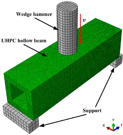
Figure 6. Finite-element model.
The numerical simulations were performed on a high-performance computing platform with the following specifications: an Intel Xeon Scalable Platinum 8457C processor with 96 cores and 192 threads, NVIDIA Quadro A2000 6 GB GDDR6 Professional Graphics Card, a base frequency of 2.6 GHz, a maximum turbo frequency of 3.8 GHz, and a TDP of 350 W, based on the latest Sapphire Rapids architecture. The processor supports a maximum memory frequency of 4,800 MHz and cutting-edge technologies, including Intel® AMX, Intel® SSE4.2, Intel® AVX, Intel® AVX2, and Intel® AVX-512 instruction sets. Eight processors were employed in parallel for the finite element simulations to significantly enhance computational efficiency.
The concrete damaged plasticity (CDP) model in ABAQUS was employed to simulate the nonlinear mechanical behavior of UHPC under tensile and compressive loading (Zhu et al., 2020). When defining the UHPC material properties using the CDP model, the stress–strain relationship must be converted into a stress–inelastic strain relationship. The derivation of the tensile and compressive stress–strain relationships for UHPC is as follows:
Where
If the damage parameters of UHPC during stretching and compression are activated when it reaches the yield strength, the damage parameters are calculated as follows:
Where

Table 1. Material parameters of UHPC hollow beams.
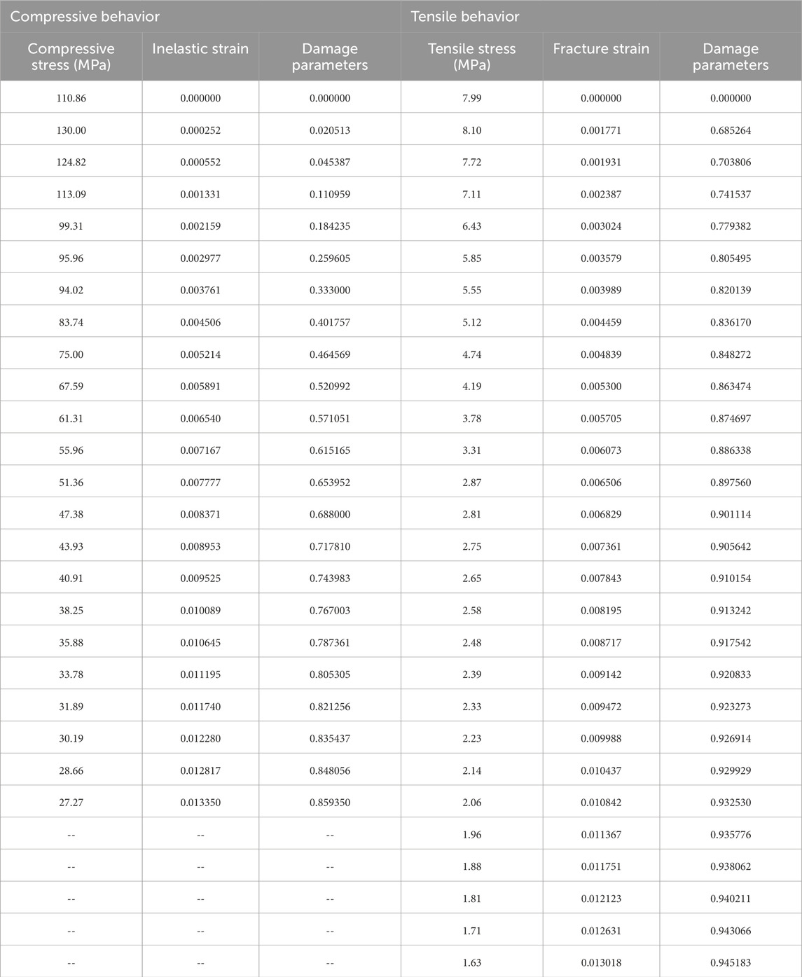
Table 2. Material parameters of UHPC.
In the definition of the concrete damaged plasticity (CDP) material properties, it is also necessary to specify the following parameters: the dilation angle, eccentricity, the ratio of the second stress invariant under tensile to compressive loading (ensuring the maximum principal stress is negative), the ratio of the initial equiaxial compressive yield stress to the uniaxial compressive yield stress, and the viscosity parameter. Based on existing research findings, these five parameters are defined as 15°, 0.1, 1.16, 0.67, and 0, respectively (Al-Osta et al., 2017).
Previous studies have indicated that UHPC demonstrates a certain rate dependency under impact loading (Gan et al., 2024; Feng et al., 2025). As the strain rate increases, the strength of the concrete also increases. The rate dependency of the current simulation is described by a “radial enhancement” approach (Zhou et al., 2023; Kong et al., 2018):
Where
3.2 Verification of the FE model
Figure 7 compares the experimental and simulated dynamic response processes of the UHPC hollow beam under a 1.0 m drop-weight impact. In the numerical simulation, the red regions in the tensile failure contour represent structural fracture. The simulated deformation modes align well with experimental observations. The tensile failure contour reveals that during the initial peak load phase, tension-dominated zones emerged at the bottom and mid-span regions of the UHPC hollow beam. As the response progressed, cracks initiated and propagated upward, leading to a gradual loss of load-bearing capacity. Complete structural failure occurred after a through-thickness fracture. Notably, the finite element simulation assumed a homogeneous UHPC material and did not account for steel fiber effects, thus omitting the fiber pull-out phase observed in experiments.
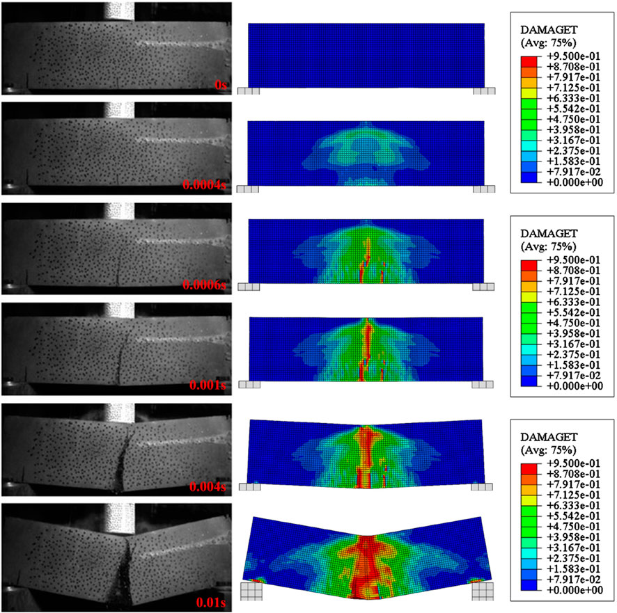
Figure 7. Dynamic response process comparison between the experimental and numerical simulation results.
The reliability of the numerical model was further validated by comparing the simulated and experimental impact force–time histories (Figure 8). The measured peak impact forces from the tests were 0.49 kN (1 m drop weight) and 0.39 kN (0.1 m drop weight), while the numerically simulated peak impact forces were 0.51 kN (1 m drop weight) and 0.38 kN (0.1 m drop weight), corresponding to relative errors of 3.92% and 2.63%, respectively. The simulated initial peak forces matched the experimental results closely. Due to the assumption of material homogeneity in the simulation (neglecting steel fiber pull-out effects), the post-peak force decayed more rapidly as cracks developed, ultimately stabilizing as the structure lost its integrity.
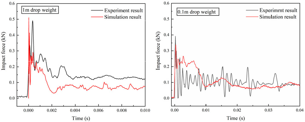
Figure 8. Impact force history comparison between the experimental and numerical simulation results.
The CDP model used for UHPC exhibits significant sensitivity to compression and tensile damage parameters as well as strain rate. Under impact loading, the UHPC hollow beam primarily responds through bending and shear, where changes in compressive behavior have a lesser influence on the overall dynamic response than tensile parameters. UHPC demonstrates a notable strain-rate strengthening effect, and whether the strain-rate effect is considered becomes crucial for accurately predicting the impact force. Neglecting this effect may lead to severe underestimation of the structural stiffness and load-bearing capacity. Furthermore, variations in boundary conditions can significantly affect the final failure mode of the structure. Therefore, in the numerical simulations, the compressive and tensile damage parameters of the material were determined through experimental tests, the strain-rate effect was incorporated based on existing research findings, and the boundary conditions were closely aligned with the actual test setup. Comparisons between the numerical simulations and experimental results in terms of deformation failure modes and load-time histories confirm that the current finite element model demonstrates a higher reliability.
4 Parameter analysis
Under the loading condition of a drop hammer height of 1 m, this study investigates the influence of geometric parameters, including structural width, height, and thickness in both directions, on the impact resistance of UHPC hollow beams while maintaining a constant cross-sectional area. Table 3 summarizes the geometric parameters of different configurations, where h and b denote the height and width of the UHPC hollow beam, respectively, and th and tb represent the thickness along the height and width directions.
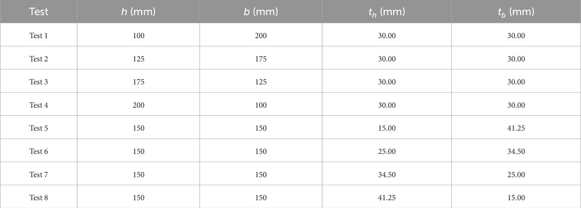
Table 3. Geometric parameters of UHPC hollow beams.
4.1 Influence of h/b
Figure 9 presents the final deformation modes of UHPC hollow beams with a drop hammer height of 1 m and th = tb = 30 mm under varying h/b ratios. The control group’s structural dimensions are specified in Section 2.1. It can be observed that the crack propagation in configurations with h/b = 0.7 and h/b = 1.4 is comparable to that of the control group, with the h/b = 0.7 case exhibiting the least crack propagation. When h/b = 0.5, cracks in the UHPC hollow beam propagate from the central cross-section along the height direction toward both sides under the loading center. For h/b = 2.0, catastrophic failure occurs at the mid-span of the beam. Excessively small h/b ratios increase fracture extent along the length direction, while overly large h/b ratios aggravate structural damage.
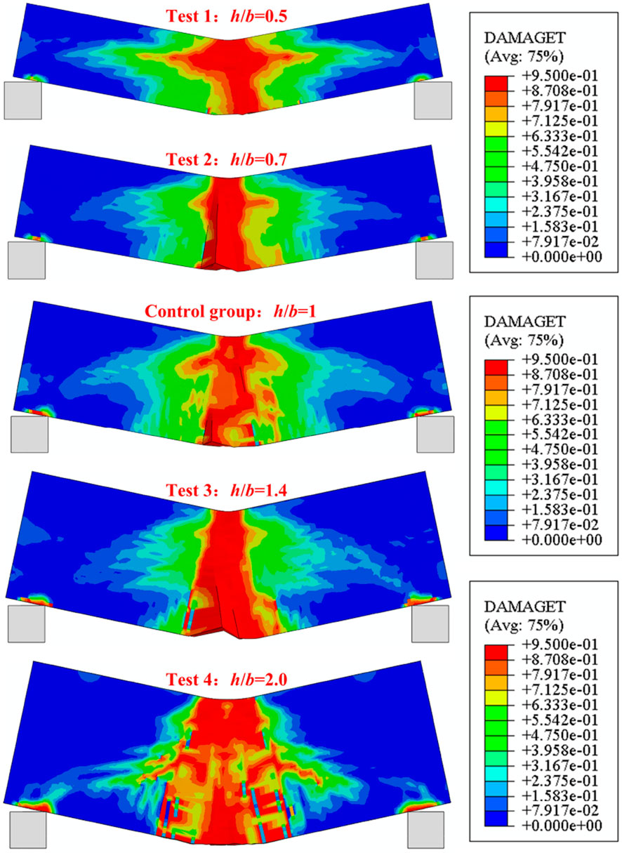
Figure 9. Deformation modes of UHPC hollow beams under different h/b ratios.
A quantitative analysis of the impact force–time histories for UHPC hollow beams with different h/b ratios is shown in Figure 10. The control group exhibits an impact force peak of 0.51 kN. The UHPC hollow beam with h/b = 2.0 achieves the highest impact force peak of 1.33 kN, representing a 61.7% increase compared to that of the control group. In contrast, the h/b = 0.7 configuration shows the lowest peak of 0.45 kN, 11.8% lower than that of the control group. The beam with h/b = 1.4 demonstrates stable load-bearing capacity after the initial peak force phase but loses load-bearing capacity after 0.0006 s, with a peak impact force (0.57 kN) close to that of the control group.
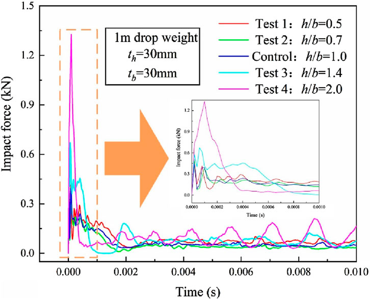
Figure 10. Impact force–time history of UHPC hollow beams under different h/b ratios.
4.2 Influence of th/tb
Figure 11 illustrates the final deformation modes of UHPC hollow beams under different th/tb ratios. When th/tb < 1, the structure exhibits a higher fracture extent, with structural damage intensifying as th/tb decreases. The configuration with th/tb = 0.36 undergoes complete fracture and catastrophic failure. In contrast, UHPC hollow beams with th/tb > 1 experience less severe damage, achieving minimal deformation at th/tb = 2.75. Therefore, increasing the wall thickness along the height direction during structural design can enhance performance.
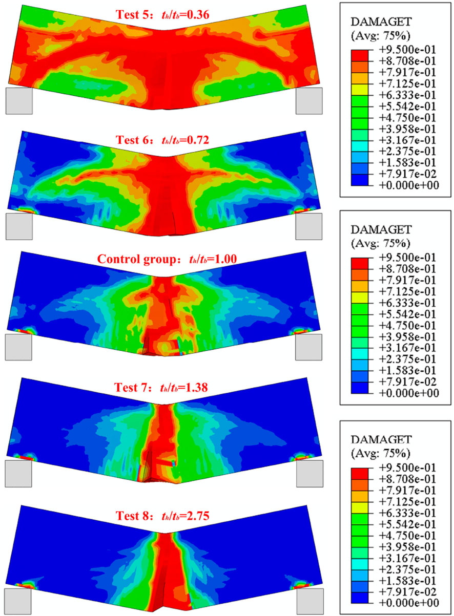
Figure 11. Deformation modes of UHPC hollow beams under different th/tb ratios.
A quantitative analysis of the impact force–time histories for UHPC hollow beams with different th/tb ratios is shown in Figure 12. The beam with th/tb = 0.36 achieves the highest impact force peak of 1.09 kN, 53.2% higher than that of the control group, while the th/tb = 1.38 case shows the lowest peak of 0.31 kN, 39.2% lower than that of the control group. For configurations with th/tb > 1, the reduced thickness along the width direction leads to pronounced shear effects on the loaded surface under impact, delaying the initial peak force compared to th/tb < 1 cases. Beams with t th/tb < 1 exhibit higher impact force peaks and greater overall stiffness but suffer more severe damage post-impact.
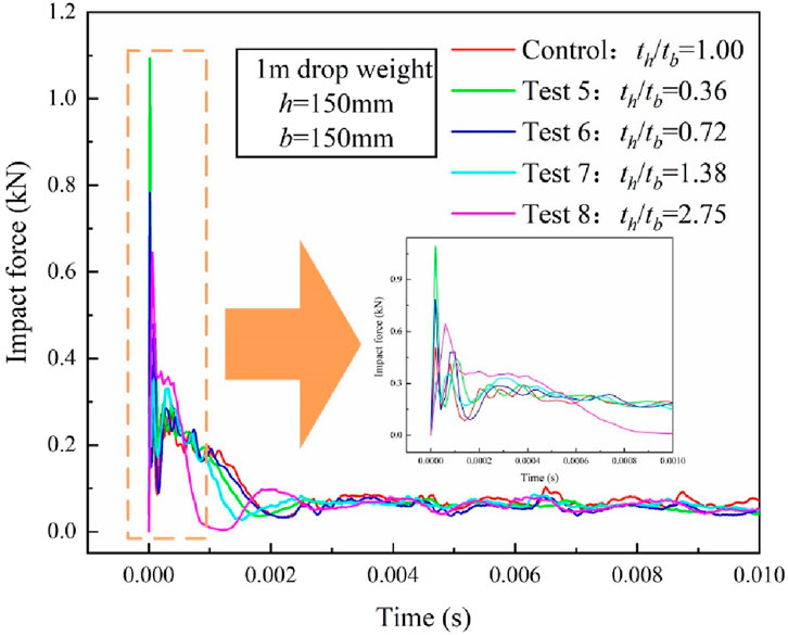
Figure 12. Impact force–time history of UHPC hollow beams under different th/tb ratios.
Compared to the aspect ratio (h/b), UHPC hollow beams with smaller thicknesses along the height direction (th) demonstrate more pronounced damage and fracture extent. During structural design, it is critical to ensure sufficient global stiffness and rationally define the h/b ratio to achieve optimal impact resistance.
In the current study on the dynamic response of UHPC hollow beams under impact loading, the following idealizations were adopted:
1. The load was applied at the center of the structure;
2. The loading type was low-velocity impact;
3. The UHPC beam was idealized as a thin-walled structure with moderate wall thickness;
4. The UHPC mix proportion and steel fiber content were consistent across different loading rates;
5. The UHPC material was modeled using an idealized concrete plastic damage model in the finite element analysis.
The above idealizations allow qualitative and quantitative predictions of the deformation and failure modes of UHPC hollow beams under impact within the studied parameter range. Further experimental studies tailored to specific load and boundary conditions will be necessary to extend the analysis to a broader spectrum of impact loads and structural material/geometric parameters. Additionally, parameters in the finite element model should be calibrated based on existing numerical results to improve the material–structure database. In practical applications, engineers and designers may use the established dynamic response database of UHPC hollow beams for preliminary assessment. Subsequently, the tailored design of the material and structure of UHPC hollow beams can be carried out according to specific project requirements.
5 Conclusion
The dynamic response of UHPC hollow beams under drop hammer impact loading was investigated through experimental tests and numerical simulations. High-speed cameras were employed to record the structural dynamic response process, and drop hammer experiments were conducted to validate the reliability of the finite element model. Based on numerical simulations, the influence of structural width, height, and thickness in both directions on the impact resistance of UHPC hollow beams under a constant cross-sectional area was discussed in detail. The main conclusions are as follows:
1. Experimental observations: The dynamic response of UHPC hollow beams under impact loading was divided into four stages: the initial peak load phase, the steel fiber pull-out phase, the unloading phase, and the structural stabilization phase.
2. Effect of aspect ratio (h/b): When the thickness of the UHPC hollow beam remained constant, the peak impact load increased with the h/b ratio. However, the configuration with h/b = 1.4 exhibited stable load-bearing capacity after the initial peak load phase, demonstrating better impact resistance and a lower peak impact load.
3. Effect of thickness ratio (th/tb): For a fixed h/b ratio, the peak impact load increased as th/tb decreased. The beam with th/tb = 0.36 experienced complete fracture and catastrophic failure, whereas the configuration with th/tb = 2.75 showed minimal deformation.
This study provides the first systematic comparison of aspect and thickness ratios for UHPC hollow beams under impact, introducing clear design strategies for optimizing performance. The findings establish practical guidelines for selecting geometric parameters to tailor impact resistance, enabling safer, more efficient, and lightweight designs in real-world applications such as blast-resistant barriers, bridge piers, and protective infrastructures. By directly linking geometric optimization to structural performance, this work offers tangible insights for advancing the use of UHPC in impact-sensitive engineering applications.
6 Directions for future research
This study focused on analyzing the influence of geometric parameters on the impact resistance of UHPC hollow beams and established structural response patterns. Future research could explore filling UHPC hollow beams with other concrete materials to develop high-performance UHPC composite structures. However, the material properties of the filler (e.g., hydration, moisture expansion, thermal effects, autogenous shrinkage, and drying shrinkage of UHPC) may significantly affect structural durability and protective performance. Addressing these interactions remains a critical challenge for optimizing such composite systems.
Data availability statement
The original contributions presented in the study are included in the article/supplementary material, further inquiries can be directed to the corresponding author.
Author contributions
LS: Conceptualization, Methodology, Writing – original draft. LG: Data curation, Funding acquisition, Software, Writing – review and editing. ZH: Funding acquisition, Methodology, Validation, Writing – review and editing. TZ: Supervision, Validation, Writing – review and editing.
Funding
The author(s) declare that financial support was received for the research and/or publication of this article. The authors gratefully acknowledge the financial supports by the Natural Science Foundation of Shanxi Province (202403021222522 and 202203021222131). It is great pleasures to thank all the reviewers who participated in the review during the preparation of this manuscript.
Conflict of interest
Authors LS, ZH, and TZ were employed by Shanxi Transportation Technology Research & Development Co., Ltd.
Authors LS, ZH, and TZ were employed by Shanxi Transportation Research Institute Group Co., Ltd.
The remaining author declare that the research was conducted in the absence of any commercial or financial relationships that could be construed as a potential conflict of interest.
Generative AI statement
The author(s) declare that no Generative AI was used in the creation of this manuscript.
Any alternative text (alt text) provided alongside figures in this article has been generated by Frontiers with the support of artificial intelligence and reasonable efforts have been made to ensure accuracy, including review by the authors wherever possible. If you identify any issues, please contact us.
Publisher’s note
All claims expressed in this article are solely those of the authors and do not necessarily represent those of their affiliated organizations, or those of the publisher, the editors and the reviewers. Any product that may be evaluated in this article, or claim that may be made by its manufacturer, is not guaranteed or endorsed by the publisher.
References
Al-Osta, M., Isa, M., Baluch, M., and Rahman, M. (2017). Flexural behavior of reinforced concrete beams strengthened with ultra-high performance fiber reinforced concrete. Constr. Build. Mater. 134, 279–296. doi:10.1016/j.conbuildmat.2016.12.094
Astarlioglu, S., and Krauthammer, T. (2014). Response of normal-strength and ultra-high-performance fiber-reinforced concrete columns to idealized blast loads. Eng. Struct. 61, 1–12. doi:10.1016/j.engstruct.2014.01.015
Bajaber, M., and Hakeem, I. (2021). UHPC evolution, development, and utilization in construction: a review. J. Mater. Res. Technol. 10, 1058–1074. doi:10.1016/j.jmrt.2020.12.051
Fan, W., Shen, D., Yang, T., and Shao, X. (2019). Experimental and numerical study on low-velocity lateral impact behaviors of RC, UHPFRC and UHPFRC-strengthened columns. Eng. Struct. 191, 509–525. doi:10.1016/j.engstruct.2019.04.086
Feng, W., Li, J., Guan, J., Mai, J., Yang, F., Li, S., et al. (2025). Strain-rate effect of mechanical properties on ultra high-performance concrete under impact loads: review and systematic analysis. Archives Civ. Mech. Eng. 25, 122. doi:10.1007/s43452-025-01178-7
Fujikake, K., Senga, T., Ueda, N., Ohno, T., and Katagiri, M. (2006). Study on impact response of reactive powder concrete beam and its analytical model. J. Adv. Concr. Technol. 4 (1), 99–108. doi:10.3151/jact.4.99
Gan, L., Liu, Y., Zhang, Z., Shen, Z., Li, L., Zhang, H., et al. (2024). Experimental investigation of the dynamic mechanical properties of concrete under different strain rates and cyclic loading. Case Stud. Constr. Mater. 20, e02750. doi:10.1016/j.cscm.2023.e02750
Jia, P., Wu, H., Wang, R., and Fang, Q. (2021). Dynamic responses of reinforced ultra-high performance concrete members under low-velocity lateral impact. Int. J. Impact Eng. 150, 103818. doi:10.1016/j.ijimpeng.2021.103818
Khosravani, M., Wagner, P., Frohlich, D., and Weinberg, K. (2019). Dynamic fracture investigations of ultra-high performance concrete by spalling tests. Eng. Struct. 201, 109844. doi:10.1016/j.engstruct.2019.109844
Kong, X., Fang, Q., Chen, L., and Wu, H. (2018). A new material model for concrete subjected to intense dynamic loadings. Int. J. Impact Eng. 120, 60–78. doi:10.1016/j.ijimpeng.2018.05.006
Li, J., Wu, C., and Hao, H. (2015). An experimental and numerical study of reinforced ultra-high performance concrete slabs under blast loads. Mater. and Des. 82, 64–76. doi:10.1016/j.matdes.2015.05.045
Tayeh, B., Aadi, A., Hilal, N., Bakar, B., and Ai-Tayeb, M. (2019). Properties of ultra-high-performance fiber-reinforced concrete (UHPFRC) -A review paper. AIP Conference Proceedings.
Wang, W., Wu, C., Li, J., Liu, Z., and Lv, Y. (2019a). Behavior of ultra-high performance fiber-reinforced concrete (UHPFRC) filled steel tubular members under lateral impact loading. Int. J. Impact Eng. 132, 103314. doi:10.1016/j.ijimpeng.2019.103314
Wang, W., Wu, C., Li, J., Liu, Z., and Zhi, X. (2019b). Lateral impact behavior of double-skin steel tubular (DST) members with ultra-high performance fiber-reinforced concrete (UHPFRC). Thin-Walled Struct. 144, 106351. doi:10.1016/j.tws.2019.106351
Wei, J., Li, J., and Wu, C. (2019). An experimental and numerical study of reinforced conventional concrete and ultra-high performance concrete columns under lateral impact loads. Eng. Struct. 201, 109822. doi:10.1016/j.engstruct.2019.109822
Wu, H., Ren, G., Fang, Q., and Liu, J. (2019). Response of ultra-high performance cementitious composites filled steel tube (UHPCC-FST) subjected to low-velocity impact. Thin-Walled Struct. 144, 106341. doi:10.1016/j.tws.2019.106341
Xue, J., Briseghellaa, B., Huang, F., Nuti, C., Tabatabai, H., and Chen, B. (2020). Review of ultra-high performance concrete and its application in bridge engineering. Constr. Build. Mater. 260, 119844. doi:10.1016/j.conbuildmat.2020.119844
Yan, J., Liu, Y., Bai, F., Ni, X., Xu, Y., Yan, Z., et al. (2022). Dynamic response of GFRP-reinforced UHPC beams under close-in blast loading. Mater. and Des. 223, 111140. doi:10.1016/j.matdes.2022.111140
Yoo, D., Banthia, N., Kim, S., and Yoon, Y. (2015). Response of ultra-high-performance fiber-reinforced concrete beams with continuous steel reinforcement subjected to low-velocity impact loading. Compos. Struct. 126, 233–245. doi:10.1016/j.compstruct.2015.02.058
Yoo, D., Banthia, N., and Yoon, Y. (2016). Impact resistance of ultra-high performance fiber-reinforced concrete with different steel fibers. 9th Rilem International Symposium on Fiber Reinforced Concrete (BEFIB 2016), 398–405.
Zhou, M., Lu, W., Song, J., and Lee, G. (2018). Application of ultra-high performance concrete in bridge engineering. Constr. Build. Mater. 186, 1256–1267. doi:10.1016/j.conbuildmat.2018.08.036
Zhou, F., Su, Q., Cheng, Y., and Wu, H. (2023). A novel dynamic constitutive model for UHPC under projectile impact. Eng. Struct. 280, 115711. doi:10.1016/j.engstruct.2023.115711
Keywords: impact loading, UHPC beam, deformation mode, dynamic response, failure behavior
Citation: Shen L, Guo L, Hou Z and Zhang T (2025) Dynamic response of ultra-high-performance concrete hollow beams under impact loading. Front. Mater. 12:1684084. doi: 10.3389/fmats.2025.1684084
Received: 12 August 2025; Accepted: 17 September 2025;
Published: 16 October 2025.
Edited by:
Yu-Fei Wu, RMIT University, AustraliaReviewed by:
Mohammad M. Karimi, Tarbiat Modares University, IranJie Wei, Hebi University of Technology, China
Gokhan Dok, Sakarya University of Applied Sciences, Türkiye
Copyright © 2025 Shen, Guo, Hou and Zhang. This is an open-access article distributed under the terms of the Creative Commons Attribution License (CC BY). The use, distribution or reproduction in other forums is permitted, provided the original author(s) and the copyright owner(s) are credited and that the original publication in this journal is cited, in accordance with accepted academic practice. No use, distribution or reproduction is permitted which does not comply with these terms.
*Correspondence: Zebiao Hou, MTg4MzQxMjAyMzhAMTYzLmNvbQ==