 Weixian Che1
 Han Zhang
- 1Guangdong Power Grid Corporation Limited, Guangzhou, China
- 2China Academy of Building Research, Beijing, China
Introduction: Based on a transformer station project, this paper conducts the design and analysis of retaining structures for transformer stations in hilly areas.
Methods: According to the geological conditions and soil-rock properties combined with in-situ experiments and laboratory tests, the design parameters of the slope were obtained. The type of the retaining wall was calculated by using the arc sliding method, and the construction and monitoring of the slope project were elaborated. Meanwhile, an detailed and comprehensive discussion was conducted on the retaining methods in the construction of substations in hilly areas. The types of retaining structures adopted for slope supporting were summarized to provide reference and guidance for the design of transformer stations in backfill areas.
Results: The safety factor varies greatly under different working conditions, and the most dangerous working condition is heavy rain.
Discussion: Slope support in hilly areas is a scientific, rigorous and comprehensive technical work. The designer of the transformer station's slope should take into account local conditions, carefully consider the advantages and disadvantages, and have a thorough understanding of the site's topography, geology, and geotechnical characteristics.
1 Introduction
With the rapid development of the global economy, the electricity consumption of urban life and industrial and agricultural production continues to increase, and more and more power grid projects are being built in mountainous and hilly areas where landslides, mudslides, flood disasters, seismic activities, and other phenomena often occur (Bai et al., 2025a). The construction of substations in this area should give full consideration to their specific environmental conditions, put forward a design scheme according to local conditions, and reduce both the damage of substation construction to the ecological environment and the impact of the environment on substation operation (Fathipour et al., 2021; Sharma and Soni, 2024; Sarıbaş and Erbatur, 1996).
The reinforcement method of the slope can be divided into active and passive methods (Bai et al., 2025b). Active reinforcement mainly uses geotechnical materials such as anchors and geogrids. Passive reinforcement uses retaining wall structures, including gravity retaining walls, buttress retaining walls, cantilever retaining walls, sheetpile walls, etc. (Chen, 2005). This article introduces the application of a gravity retaining wall and its reinforcement in a hilly area station based on a transformer station project.
2 Project overview
An image of the project site is shown in Figure 1. Slope 1#, which is on the north side of the station, is protected by mortar rubble masonry. The slope length is approximately 90 m, the slope height is 3.6 m–8.0 m, and the thickness of the protection pavement is 30 cm. The south slope of the station is combined with retaining wall 1#, slope protection 2#, and retaining wall 2#. Among them, retaining wall 1# is an inclined shoulder wall with rough stone concrete, whose length and height are approximately 40 m and 2.3 m–3.0 m, respectively. Slope 2# uses the same material as slope 1#, and its length and height are approximately 66.8 m and 4.2 m–5.2 m, respectively. Retaining wall 2# is a vertical embankment wall with C15 rough stone concrete, and its length and height are approximately 66.8 m and 2 m∼6 m.
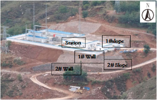
Figure 1. Image of the transformer station.
3 Geological conditions
The site of the transformer where the station is located is hilly landform, and the terrain is high in the north and low in the south. Figure 2 shows the stratigraphic profile of the site. The strata of the site are distributed as follows:
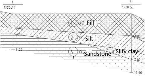
Figure 2. Stratigraphic profile.
Artificial fill: Brownish-yellow, slightly wet, slightly densely mixed with a large amount of gravel, occasionally drifting stone.
Silt soil: Brownish-yellow, slightly wet, slightly dense ∼ medium-dense, uneven soil quality, mixed gravel particles, and occasional stones are seen locally.
Silty clay: Brown, loose, malleable, sporadic ginger, and iron oxide.
Strongly weathered sandstone: Gray-white, purple-red, rock mass is broken, weathering is strong, weathering is fragmented, sandy structure, thin layered structure.
The physical and mechanical parameters of each soil determined by in-situ and laboratory tests are given in Table 1.
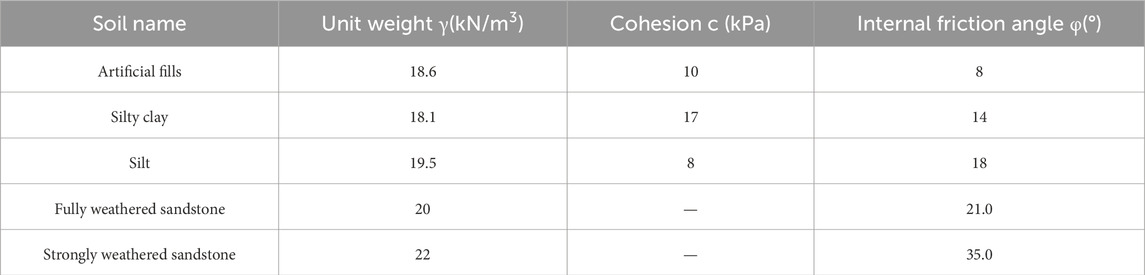
Table 1. Soil parameters.
4 Retaining structure design
The possible failure modes of a fill slope can be divided into (1) the stability of the fill body itself, that is, the instability of the entire fill body and an internal landslide of the fill soil; (2) The overall stability problem along the soils interface; (3) The overall instability of the soft layer at a certain depth along the slope (Causes, 2001; Salgado, 2022; Payan et al., 2022).
There are two methods to evaluate slope stability: the traditional limit equilibrium analysis method and the numerical simulation analysis method (finite element method, finite difference method) (Zhao Mingjie, 2003).
4.1 Limit equilibrium method
4.1.1 Planar sliding method
As shown in Figure 3, Formula 1 for calculating the safety factor (Fs) using plane sliding (Salunkhe et al., 2017) is as follows:
Figure 3. Analysis diagram of the planar sliding method.
where W is the slide block weight, KH is the horizontal seismic impact coefficient, L is the block length, and α is the sliding surface inclination.
4.2 Slip circle method
The common arc slip circle analysis uses the Swedish slice method and Bishop’s procedure. The principles of these methods are described below.
As shown in Figure 4, the Swedish slice method (Salunkhe et al., 2017; Ullah et al., 2020; Kainthola et al., 2013) assumes that the sliding surface is an arc and divides the sliding body into several blocks. Each block is assumed to be rigid and invariant; that is, the force on the side of the slice is not considered. When the slide body is in the ultimate equilibrium state, the total anti-slip torque of each slice around the center of the circle O is equal to the total sliding torque, and the safety factor can be taken as the ratio of the total anti-slip torque and the total sliding torque of each block (technical code for building slope). The calculation of Formula 2 is as follows:

Figure 4. Analysis of the Swedish slice method.
where bi,hi is the width and average height of the ith slice; γi,ci,φi,li is the severity, cohesion, internal friction angle, and arc length of the ith slice; αi is the angle between the center normal of the bottom surface of slice i (passing through the center O) and the lead straight line passing through the center O, with a positive value on the right side and negative value on the left side.
Different Fs values are calculated to obtain different Fs values assuming different slip circles, where the smallest Fs value is the safety factor of the slope.
As shown in Figure 5, the definition of the safety factor proposed by Bishop is the ratio of the shear strength of the entire slip surface to the actual shear stress, and the effect on the side of each slice is considered (Technical code for appraisal, 2013). Formulas 3 and 4 for calculating the safety factor are as follows:
where Wi is the weight of the ith slice; ci,φi, li are the cohesion force, internal friction angle, and arc length of the ith slicer; Xi,Xi+1 is the tangential force on the side of the ith slice; αi is the angle between the center normal (over the center of the circle O) on the bottom of the ith slider and the lead line of the center of the circle O.

Figure 5. Analysis diagram of Bishop’s procedure.
Because both Formula 3 and 4 contain the safety factor Fs, it must be solved by the iterative method. First, assume that Fs = 1 and calculate mαi. Then, use the above formula to find Fs, such as the calculated Fs ≠ 1, and use it to find the new mαi and Fs. Repeat this calculation until the Fs results obtained twice before and after are relatively close (Griffiths and Fenton, 2004; Huang, 2014).
4.3 Numerical simulation analysis
The slope is analyzed by numerical simulation, and the soil and rock mass are regarded as material conforming to the Mohr-Coulomb criterion. The safety factor of strength reduction is applied (Christian et al., 1994), and the calculation of Formulas 5, 6 is as follows:
Where Fs is the reduced strength safety factor; c,φ is the reduced cohesion and internal friction angle of the soil; c′,φ′ is the initial cohesion and internal friction angle of the soil.
The stability of soil slope and fractured rock slope is calculated by the slip circle method in this project. The station’s seismic intensity is 7°, and the design seismic grouping is the third group. The slope belongs to the second-level permanent slope; therefore, the safety factor is 1.3 and 1.1 in the general condition and the seismic condition, respectively (General code for engineering survey, 2021). It should be noted that the general conditions also include saturated conditions. This is because during heavy rainy weather, the groundwater level rises in the site, and fill soil and silt layers may also become aquifers. The shear strength parameters of these two soil layers also reduced appropriately. When implementing measures like retaining wall drainage and water interception ditches, the highest water level is calculated based on the ground surface elevation. The calculation results are shown in Table 2. Under unsaturated conditions, the substation slope is in a stable state, in a basic stable state under saturated conditions, and in a stable state under seismic conditions. The calculation results suggest that drainage measures should be implemented in order to avoid the saturation condition.

Table 2. Safety factor of stability analysis.
5 Construction of the retaining wall
5.1 Gravity retaining wall
Figure 6 is the cross-section of the gravity retaining wall of this project. To prevent reducing the foundation’s bearing capability, it must not be exposed, disturbed, or saturated for an extended period of time after excavation. It is best to keep the excavation between 100 mm and 200 mm thick when it is at the base elevation, and then excavate it by hand before building the foundation. Controlling the slope degree, preserving the foundation soil’s natural structure, and replacing the overexcavated area with coarse stone concrete are all important aspects of retaining wall base excavation. After the excavation, the re-inspection should be carried out according to the design size, and the next step of construction can be carried out only after the elevation is accurate. During the excavation, the retaining and drainage construction should be done to keep the soil dry, and the embedded depth of the base should not be less than 200 mm.
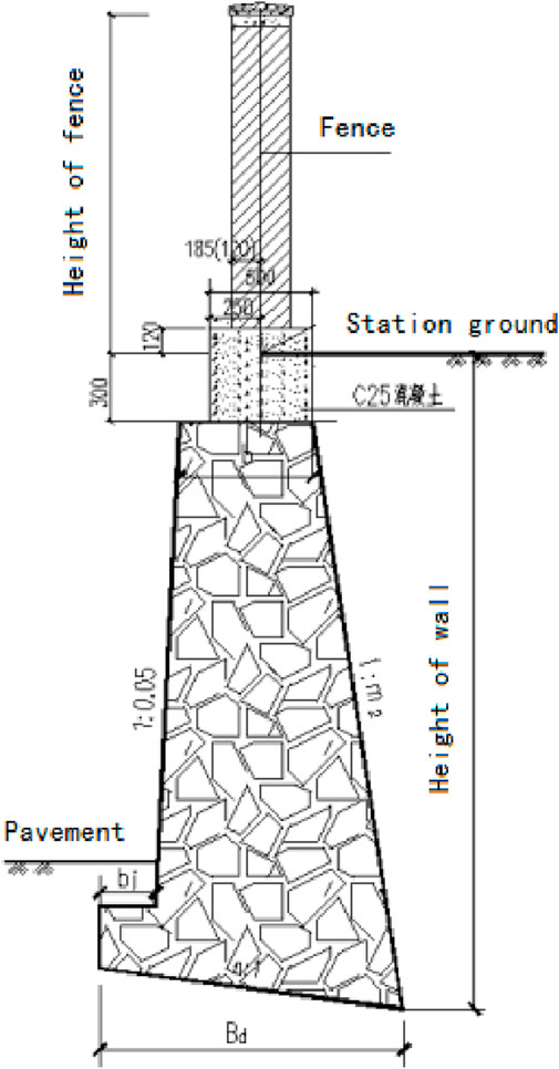
Figure 6. Retaining wall.
The stone used for stone masonry should have MU30 block strength, have a firm texture, and not peel or split from weathering. Prior to beginning masonry, the stone’s surface should be cleared of dirt, corrosion, and other contaminants. The grouting method should be used for the stone masonry, and the mortar should have a consistency of 3–5 cm and a strength of M7.5. These parameters should be suitably adjusted for climate fluctuations. The strength of the plastering mortar on the surface of the jointed mortar and the drainage ditch wall is M10. The temporary break that cannot be constructed simultaneously and must be left in place should be built into a diagonal raft, and the corner and junction of stone masonry should be constructed simultaneously. Sections of masonry are constructed with deformation joints spaced 15–20 m apart. The walls on both sides of the deformation joint should be flat without overlap, the width of the deformation joint should be 20 mm, and the joint should be filled with asphalt hemp bars. The joints also need to be filled with waterproof materials to prevent water leakage from the masonry. The waterproof material can be filled and squeezed along the inner, outside, and top sides of the wall, or it can be fastened to the end face of the wall section at the joint. The filling depth shall not be less than 15 cm to meet the waterproof requirements. Rough stone masonry should be constructed both inside and outside, in layers, and staggered up and down. The mortar should be full, the masonry’s gray joints should be 20–30 mm thick, and the big spaces between the stones should be filled with mortar first, followed by gravel blocks. The large side of the masonry foundation should be facing down, and the first stone block should be seated.
Before the construction of the retaining wall, the ground drainage system should be installed to keep the back of the wall dry to ensure construction safety (Yang and Yin, 2004). Following construction, the fill behind the wall must be compacted in layers, with a maximum layer thickness of 20 mm achieved in real time through human compaction. To guarantee the wall’s stability throughout the building process, take care that it is not impacted by ramming. The filling soil behind the wall should be made of materials with strong water permeability. When using cohesive soil as filler, an appropriate amount of sand and gravel should be added, and the friction angle within the filler must be larger than 30°. Only after the concrete of the retaining wall reaches the required strength and the filler’s compaction coefficient is at least 94% can the filling behind the wall be completed.
5.2 Slope protection construction
Figure 7 shows a section of the slope protection design, which is commonly used in soil slopes with a height of less than 8 m. Sand, gravel, and other slope protection materials must be clean and have a consistent texture. Stone materials should be weatherproof, crack-free, and have a minimum strength of MU30. The stones should be the correct thickness and size, free of moss or dirt on their surfaces, and free of delamination or honeycomb patterns. Stones must have a core thickness of at least 150 mm, despite their potential for shape variation.

Figure 7. Slope protection.
Drainage holes and expansion joints should be a part of the slope protection system. The materials used should be oil felt, asphalt boards, low-density polyethylene plastic sheets, or asphalt hemp reinforcement. Expansion joints should be placed 10–15 m apart and 20 mm wide. Every joint must be completely vertically penetrated, with at least 150 mm of implanted material. Every 2–3 m, drainage holes should be spaced in a plum blossom design, with the bottom row 300 mm above the water level of the embankment. Each drainage hole must be followed by a layer of gravel and geotextile (400 g/m2, Grade II strength), with the gravel accumulation thickness being at least 300 mm. The stone masonry should be covered with a layer of sandstone liner.
5.3 Drainage construction
The drainage project should be given careful consideration while designing the retaining structure for the transformer station because the surrounding water environment would negatively affect the project. Surface water and groundwater are typically included in drainage projects (Hack, 2002; Chen, 1995; Malkawi et al., 2000; Whitman and Bailey, 1967). The two have different goals: the former aims to keep water from leaking into the slope and remove as much rainwater as possible; the latter aims to reduce the height of the water level inside the slope. The main methods for achieving this are the installation of the drainage ditch and the drainage holes on the retaining structure.
Drainage ditches are situated at the bottom of the slopes, while water interception ditches are situated at the bottom of the northern and southern slopes. Figure 8 shows the real drainage and intercepting ditches. Drainage holes are spaced 2–3 m apart along the slopes and retaining walls on the north and south sides. Figure 9 displays the real drainage holes on the slopes and retaining walls.
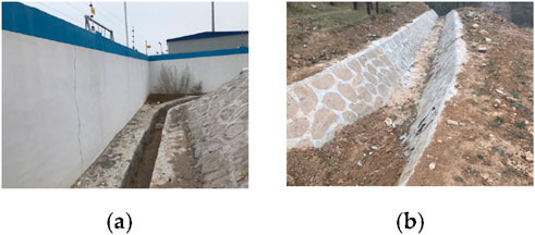
Figure 8. Drainage ditch: (a) Drainage ditch at the bottom of the slope; (b) The slope top of the slope intercepts the ditch.

Figure 9. Drainage hole. (a) Drainage hole on the south slope. (b) Drainage hole on the north slope.
To ensure the targeted effectiveness of the drainage design, the intercepting and drainage system for this project was designed based on a detailed analysis of the site’s hydrogeological conditions. Given that the terrain is higher in the north and lower in the south, the catchment area of the northern hill is approximately A = 0.15 km2. Using the local storm intensity formula for a 50-year return period, the peak flow rate was calculated as Q = 2.5 m3/s. Accordingly, the intercepting ditch at the north slope toe was designed with a trapezoidal cross-section (base width 0.8 m, depth 0.6 m) and a longitudinal gradient not less than 0.5% to ensure effective interception and diversion of upstream runoff, preventing direct scouring of the slope. The primary purpose of the drainage holes is to lower the groundwater table within the artificial fill and silt layers, whose strength parameters decrease significantly when saturated (see Table 1). Arranged in a plum blossom pattern at 2–3 m intervals, the drainage holes are 3–5 m long with an upward inclination of 5°–10° to ensure they penetrate potential slip surfaces and reach water-prone zones. Each hole contains a Φ100 mm perforated corrugated PVC pipe, wrapped externally with a 400 g/m2 filament geotextile filter layer to prevent clogging from fine particle migration.
The drainage facilities are crucial for ensuring the slope meets the safety factor requirements under saturated conditions. To verify their effectiveness, a comparative numerical simulation analysis was conducted: Case 1 (Current condition with effective drainage): As shown in Table 2 of the main text, the safety factor under saturated conditions is 1.2 with the effective drainage system in place. Case 2 (Hypothetical scenario without or with failed drainage): Simulating a scenario where the drainage system completely fails during a heavy rainstorm, causing the groundwater level to rise to within 1.5 m of the slope surface. Under this condition, the calculated safety factor drops to 1.05, below the code requirement of 1.3. This comparison clearly demonstrates that the implemented intercepting and drainage system increases the safety factor under saturated conditions from a critical value of 1.05 to a marginally stable 1.2. This highlights its vital contribution to the overall slope stability, elevating its role from ancillary to essential.
6 Discussion
6.1 Details of design and construction
In order to provide an appropriate slope design plan, a thorough examination and analysis of the site topography, landform, geology, engineering, and hydrogeological conditions are necessary when building transformer stations in hilly areas (Leshchinsky et al., 1985; Stark and Eid, 1998; Hack et al., 2003). There are many hilly areas on the earth, and building transformer stations in hilly areas is fairly popular. The primary issue is that the terrain is rough, usually high in the center and low around it, and it is undulating and irregular.
The design and computation of the slope rate and retaining structure are the primary tasks in the design. Drainage measures and slope landscaping protection are also taken into consideration. A thorough and in-depth discussion is required on the design of the retaining structure for medium and large transformer stations in hilly areas.
According to the building code and practice experience (Chen and Shao, 1988; Zhang et al., 2013), the sloping method is generally considered to design the slope of the substation first. The sloping method refers to strictly controlling the height and slope of the slope, without additional special overall reinforcement of the slope, so that the station slope can reach its own stability, which is both economical and environmentally friendly (Suman et al., 2016). There are two main forms of slopes, namely fill slopes and excavated slopes, which are different in the type of project and some related factors. For fill slopes, the project is mainly related to the type of fill and the height of the slope, which can be divided into two types according to the type of fill: soil and rock slopes. Different fills cause different requirements for the slope rate: (1) If the fill’s soil quality is ordinary, the slope rate should be 1:1.5, but if the slope is higher, it is advised to change the lower half of the fill slope’s rate to 1:1.75 for improved slope stability; (2) The portion below the design water level should be chosen based on the particular circumstances of the fill if the fill slope presents an underwater issue. It is advised to maintain the slope rate between 1:1.75 and 1:2, control the slope rate at constant water level between 1:2 and 1:3, and reinforce the lower portion in accordance with the particular water flow situation; (3) The slope rate can be 1:1 if the fill is composed of weather-resistant rocks, and it should be constructed based on the condition of the weathered rocks. There are many factors to consider in the design of excavated slopes, such as slope rate, soil properties of the slope body, geological structure characteristics, weathering and fragmentation degree of the rock, surface water, groundwater, etc. Generally, the first consideration in the design is the soil and rock properties of the slope, and the relevant design is carried out according to whether it is soil or rock. The height of the soil, its compactness, surface and groundwater, and soil genesis are all important considerations for soil slopes. Considerations for rock slopes include their own height, the geological and hydrological characteristics of the site, the type of rock, the degree of weathering and crushing, construction technique, etc. The design plan should be reviewed if needed.
In the retaining design, only the sloping method cannot meet the engineering requirements. In this case, the combination of the sloping method and retaining structure was used to stabilize and reinforce the slope. In the current engineering application, the retaining structure mainly adopts the “gravity retaining wall,” which relies on the self-weight of the retaining wall to resist the lateral soil and rock pressure and stabilize the soil and rock slope. The characteristics of a gravity retaining wall are a simple structure, a large cross-sectional size, a heavy wall, convenient construction, and local materials. A high retaining wall puts forward high requirements for foundation and masonry quality. According to engineering experience, the retaining wall’s height should not be more than 8 m for soil slopes. Generally, gravity retaining walls are advised for slopes no higher than 6 m; “rib or lattice retaining walls with anchors” are advised for slopes with high excavation; and “sheet pile wall or reinforced soil retaining walls” are advised for slopes with high fill. Table 3 shows the recommended retaining structure type for the high slope of the transformer stations.
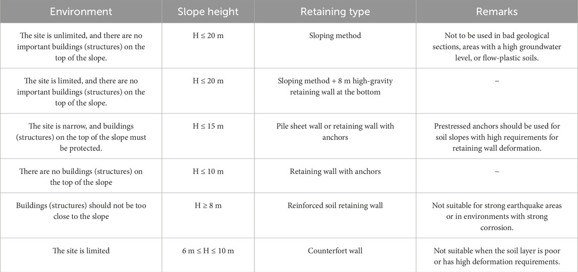
Table 3. Recommended retaining structure types for high slopes of transformer stations.
The primary components of a retaining wall are expansion joints, drainage facilities, walls, and foundations, and all the parts should be specified throughout the structure design phase. It is important to include the retaining wall foundation in the design because inadequate foundations or inappropriate foundation treatment are the main causes of retaining wall deterioration after construction. The bearing capacity of the foundation may decrease, and the earth pressure will increase if there is a problem with poor drainage in the retaining wall. Additionally, hydrostatic pressure will be generated, adding to the stress and raising hidden risks to the stability and structural strength of the retaining wall. In addition to preventing temperature stress from masonry hardening and contraction, or thermal expansion and contraction, expansion joints are employed to avoid wall fracture brought on by uneven foundation settlement.
Slope monitoring is also an essential job. Settlement and displacement observation points should be set up every 50 m–80 m at intervals of retaining walls and slope tops. The technical requirements for deformation observation should comply with the provisions of the current General Code on deformation measurement. The error of the settlement observation point shall not exceed 1.5 mm, and the error of the displacement observation point shall not exceed 10 mm. The monitoring frequency is once daily during the construction phase and can be suitably modified based on the rate of deformation. Following completion, the observation frequency is once every 15 days, and after 3 months, it is once a month. The observation period is 2 years, and the interval between observations can be modified based on the rate of deformation.
6.2 Durability and long-term performance
Given that the slope support structures for a transformer station are permanent works, their long-term performance and durability are crucial for ensuring the lifelong safe operation of the entire station. This project has considered relevant measures during the design phase, and it is recommended that attention be paid to them during long-term operation and maintenance.
6.2.1 Material durability
The M7.5 and M10 mortar and C15 rough stone concrete used in this project, located in a mountainous environment with heavy rainfall and significant temperature/humidity variations, require attention to their long-term performance. To resist carbonation and freeze–thaw cycles, an appropriate amount of air-entraining agent and waterproofing agent was added to the mortar during mixing to improve impermeability and frost resistance. For the MU30 stone, we specifically selected sandstone with strong weathering resistance (softening coefficient >0.75), which has a dense surface and is not prone to spalling, ensuring the long-term stability of the masonry from the material source.
6.2.2 Long-term maintenance of drainage systems
The effectiveness of the drainage system is the lifeline for the long-term stability of the retaining wall. Although a filter layer of gravel and geotextile (400 g/m2, Grade II strength) was installed behind the drainage holes during construction, given the rapid siltation rate in mountainous areas, it is recommended that the operation department establish a regular maintenance regime. The specific recommendation is: Before and after each rainy season, conduct a comprehensive desilting and clearing of the intercepting ditches at the slope top, the drainage ditches at the slope toe, and all drainage holes to ensure unimpeded drainage paths and prevent the wall from bearing additional hydrostatic pressure due to rising water levels.
6.2.3 Long-term sealing of structural joints
The deformation joints in this project are filled with asphalt hemp fiber. This material provides good sealing initially but may age and detach under long-term thermal expansion/contraction and minor foundation movements. During future inspections, if the original joint filler is found to have failed, it is recommended to replace it with more durable polysulfide-based building sealant or silicone sealant, which offer superior elasticity, adhesion, and weather resistance, more effectively accommodating movement and preventing water infiltration into the wall.
6.2.4 Long-term monitoring and performance
The construction phase monitoring scheme described in Section 5.3 should be extended throughout the wall’s operational life. It is recommended to re-survey the established settlement and displacement observation points in the 3rd year and 5th year after completion, and every 5 years thereafter. Simultaneously, an annual visual inspection regime should be established, focusing on checking for new cracks, tilting, bulging, signs of water seepage on the retaining walls and slope protection, and the integrity of drainage facilities. By combining periodic monitoring with routine inspections, a long-term health record for the slope support structures can be established, enabling early warning of performance degradation.
6.2.5 Long-term vegetation management
Slope vegetation effectively prevents soil erosion, but uncontrolled plant growth can potentially harm the structures. During slope greening maintenance, avoid planting deep-rooted trees, and regularly prune existing shrubs to prevent their root systems from damaging the masonry structure.
7 Conclusion
Slope support in hilly areas is a scientific, rigorous, and comprehensive technical work. The designer of the transformer station’s slope should take into account local conditions, carefully consider the advantages and disadvantages, and have a thorough understanding of the site’s topography, geology, and geotechnical characteristics. The designer should also naturally combine the application of various slope support types based on the needs of the application and the actual local situation.
Data availability statement
The raw data supporting the conclusions of this article will be made available by the authors, without undue reservation.
Author contributions
WC: Conceptualization, Writing – review and editing. WZ: Investigation, Writing – review and editing. YW: Methodology, Writing – review and editing. JG: Resources, Writing – review and editing. XG: Writing – review and editing. LL: Software, Writing – review and editing. HZ: Writing – original draft. XL: Formal Analysis, Writing – review and editing.
Funding
The author(s) declare that no financial support was received for the research and/or publication of this article.
Conflict of interest
Authors WC, WZ, YW, JG, XG, and LL were employed by Guangdong Power Grid Corporation Limited.
The remaining authors declare that the research was conducted in the absence of any commercial or financial relationships that could be construed as a potential conflict of interest.
Generative AI statement
The author(s) declare that no Generative AI was used in the creation of this manuscript.
Any alternative text (alt text) provided alongside figures in this article has been generated by Frontiers with the support of artificial intelligence and reasonable efforts have been made to ensure accuracy, including review by the authors wherever possible. If you identify any issues, please contact us.
Publisher’s note
All claims expressed in this article are solely those of the authors and do not necessarily represent those of their affiliated organizations, or those of the publisher, the editors and the reviewers. Any product that may be evaluated in this article, or claim that may be made by its manufacturer, is not guaranteed or endorsed by the publisher.
References
Bai, B., Zhang, B., Chen, H., and Chen, P. (2025a). A novel thermodynamic constitutive model of coarse-grained soils considering the particle breakage. Transp. Geotech. 50, 101462. doi:10.1016/j.trgeo.2024.101462
Bai, B., Zhang, B., Ji, Y., and Zong, Y. (2025b). A thermodynamic multi-field model for unsaturated sulfate-saline soils considering crystallization process. Comput. Geotechnics 184, 107251. doi:10.1016/j.compgeo.2025.107251
Chen, Z. (1995). Recent developments in slope stability analysis[C]//ISRM congress. ISRM. ISRM-8CONGRESS-1995-196.
Chen, Z. (2005). Stability analysis of soil slope – principles, methods and procedures. Beijing: Water Conservancy and Hydropower Press.
Chen, Z. Y., and Shao, C. M. (1988). Evaluation of minimum factor of safety in slope stability analysis. Can. Geotechnical J. 25 (4), 735–748. doi:10.1139/t88-084
Christian, J. T., Ladd, C. C., and Baecher, G. B. (1994). Reliability applied to slope stability analysis. J. Geotechnical Eng. 120 (12), 2180–2207. doi:10.1061/(asce)0733-9410(1994)120:12(2180)
Fathipour, H., Payan, M., and Chenari, R. J. (2021). Limit analysis of lateral earth pressure on geosynthetic-reinforced retaining structures using finite element and second-order cone programming. Comput. Geotechnics 134, 104119. doi:10.1016/j.compgeo.2021.104119
Griffiths, D. V., and Fenton, G. A. (2004). Probabilistic slope stability analysis by finite elements. J. Geotechnical Geoenvironmental Eng. 130 (5), 507–518. doi:10.1061/(asce)1090-0241(2004)130:5(507)
Hack, R., Price, D., and Rengers, N. (2003). A new approach to rock slope stability–a probability classification (SSPC). Bull. Eng. Geol. Environ. 62 (2), 185–184. doi:10.1007/s10064-002-0171-4
Huang, Y. H. (2014). Slope stability analysis by the limit equilibrium method: fundamentals and methods. Am. Soc. Civ. Eng. doi:10.1061/9780784412886
Kainthola, A., Verma, D., and Thareja, R. (2013). A review on numerical slope stability analysis. Int. J. Sci. Eng. Technol. Res. (IJSETR) 2 (6), 1315–1320.
Leshchinsky, D., Baker, R., and Silver, M. L. (1985). Three dimensional analysis of slope stability. Int. J. Numer. Anal. Methods Geomechanics 9 (3), 199–223. doi:10.1002/nag.1610090302
Malkawi, A. I. H., Hassan, W. F., and Abdulla, F. A. (2000). Uncertainty and reliability analysis applied to slope stability. Struct. Saf. 22 (2), 161–187. doi:10.1016/s0167-4730(00)00006-0
Payan, M., Fathipour, H., Hosseini, M., Jamshidi Chenari, R., and Shiau, J. S. (2022). Lower bound finite element limit analysis of geo-structures with non-associated flow rule. Comput. Geotechnics 147, 104803. doi:10.1016/j.compgeo.2022.104803
Salunkhe, D. P., Bartakke, R. N., and Chvan, G. (2017). An overview on methods for slope stability analysis. Int. J. Eng. Res. and Technol. (IJERT) 6 (03), 2278. doi:10.17577/IJERTV6IS030496
Sarıbaş, A., and Erbatur, F. (1996). Optimization and sensitivity of retaining structures. J. Geotechnical Eng. 122 (8), 649–656. doi:10.1061/(asce)0733-9410(1996)122:8(649)
Sharma, D. I. C., and Soni, G. S. (2024). Understanding the impact of belt walls on progressive collapse in high-rise structures. Int. J. Eng. Trends Appl. (IJETA) 11 (3), 59–61.
Stark, T. D., and Eid, H. T. (1998). Performance of three-dimensional slope stability methods in practice. J. Geotechnical Geoenvironmental Eng. 124 (11), 1049–1060. doi:10.1061/(asce)1090-0241(1998)124:11(1049)
Suman, S., Khan, S. Z., Das, S. K., and Chand, S. K. (2016). Slope stability analysis using artificial intelligence techniques. Nat. Hazards 84 (2), 727–748. doi:10.1007/s11069-016-2454-2
Technical code for appraisal (2013). Technical code for appraisal and reinforcement of building slope (GB50843-2013).
Ullah, S., Khan, M. U., and Rehman, G. (2020). A brief review of the slope stability analysis methods. Geol. Behav. 4 (2), 73–77. doi:10.26480/gbr.02.2020.73.77
Whitman, R. V., and Bailey, W. A. (1967). Use of computers for slope stability analysis. J. Soil Mech. Found. Div. 93 (4), 475–498. doi:10.1061/jsfeaq.0001003
Yang, X. L., and Yin, J. H. (2004). Slope stability analysis with nonlinear failure criterion. J. Eng. Mech. 130 (3), 267–273. doi:10.1061/(asce)0733-9399(2004)130:3(267)
Zhang, Y., Chen, G., Zheng, L., Li, Y., and Zhuang, X. (2013). Effects of geometries on three-dimensional slope stability. Can. Geotechnical J. 50 (3), 233–249. doi:10.1139/cgj-2012-0279
Keywords: hilly areas, transformer stations, slopes, retaining structures, drainage
Citation: Che W, Zhu W, Wang Y, Guo J, Gao X, Li L, Zhang H and Li X (2025) Design and analysis of retaining structures for transformer stations in hilly areas. Front. Mater. 12:1711125. doi: 10.3389/fmats.2025.1711125
Received: 23 September 2025; Accepted: 13 October 2025;
Published: 10 November 2025.
Edited by:
Bing Bai, Beijing Jiaotong University, ChinaReviewed by:
Chen Peipei, Beijing University of Civil Engineering and Architecture, ChinaRui Zhou, University of Science and Technology Beijing, China
Copyright © 2025 Che, Zhu, Wang, Guo, Gao, Li, Zhang and Li. This is an open-access article distributed under the terms of the Creative Commons Attribution License (CC BY). The use, distribution or reproduction in other forums is permitted, provided the original author(s) and the copyright owner(s) are credited and that the original publication in this journal is cited, in accordance with accepted academic practice. No use, distribution or reproduction is permitted which does not comply with these terms.
*Correspondence: Han Zhang, emhhbmdoYW5AY2Fici5jb20uY24=