 Wen-Zhe Gu
 Bei-Yan Zhang*Cheng-Yong LiuChao-Feng YuanYan-Bin YangWen-Tao LiuXin-Fu ZhangHeng-Jian Qiu
- China Coal Energy Research Institute Co., Ltd., Xi’an, Shaanxi, China
Introduction: The mining roadways for the exceptionally thick coal seams 3-5 at Tashan Colliery in the Datong Mining District faced the challenge of significant and uncontrollable surrounding rock deformation under hard roof strata conditions, posing a serious threat to safe and efficient operations.
Methods: A systematic methodology combining field investigation, theoretical analysis, numerical modeling, and engineering practice was employed. Rock mechanics tests and borehole imaging were first conducted to determine the physico-mechanical parameters and joint characteristics of the surrounding rock in the 5,230 auxiliary haulage roadway. FLAC3D simulation was then used to analyze the deformation behavior of the roadway under different mining phases. Subsequently, a mechanical model of the sectional coal pillar was established based on load estimation to analyze the pressure relief mechanism via hard roof caving. Key caving parameters were optimized using UDEC numerical simulation.
Results: The numerical simulation optimized the critical roof caving parameters: a caving height of 36 m and a caving angle of 11°. Furthermore, the optimal support parameters were determined as an anchor cable length of 5.5 m, a spacing of two cables per row, and a grouting pressure of 3 MPa. Field industrial trials and monitoring data demonstrated that the implemented technical strategy effectively controlled the deformation of the roadway rock mass.
Discussion: The integrated technical solution of “roof cutting and pressure relief combined with hollow grouting anchor cables” successfully ensured the long-term stability of the roadway. This study provides a crucial theoretical foundation and technical support for safe and efficient coal mining under similar geological conditions of hard roof and exceptionally thick coal seams.
1 Introduction
Currently, China lacks explicit regulations concerning exceptionally thick coal seams, though it is generally accepted that seams exceeding 8 m in thickness qualify as such (Zhan et al., 2025; Zhang et al., 2025; Wang J. et al., 2025; Yin et al., 2025; Yue et al., 2025). The Datong mining area, with its coal seams ranging from 14 to 20 m in thickness, represents a typical region for mining exceptionally thick coal seams (Lian et al., 2023; Peng, 2023; Xie et al., 2022; Wu et al., 2022; Qiu et al., 2025; Zhou et al., 2025). With the continuous upgrading of underground coal mining equipment, top coal caving has become the primary method for exploiting thick and extra-thick seams. Extensive mining practice indicates that the goaf formed by top coal caving is extensive. Particularly under conditions such as a hard roof, this can readily lead to issues like roof suspension. Mining pressure in the working face manifests intensely, compromising the stability of roadways and complicating roadway support (Chen et al., 2025; Shao et al., 2025; Wang H. et al., 2025; Zechao et al., 2024; Zhang et al., 2026; Dai et al., 2025).
To achieve stability control of roadways in the extraction of ultra-thick coal seams with hard roofs, numerous researchers have conducted extensive studies.
1. Research on the mechanism and parameters of pressure relief by cutting the top. Yang et al. (2023) established a typical model of the overburden structure following roof pre-cracking, investigating the failure mechanisms of the roof coal and overburden as well as the impact of roof cutting parameters on the stability of longwall roadways. This research provides evidence for the importance of roof pre-cracking in the application of roof caving longwall mining with roadway retention in extra-thick coal seams. Xinshuai et al. (2020) employed physical model tests and numerical simulations to investigate the movement patterns, failure mechanisms, and fracture evolution of hard roof strata following roof caving and pressure relief in longwall roadways of thick coal seams. Ma et al. (2024) studied roadway deformation and failure mechanisms under thick, hard roof conditions, proposing a relationship between roof caving extent and roadway roof deformation based on these mechanisms. Their work provides valuable references for roadway stability management in complex geological conditions. Pan et al. (2025) investigated the fracture evolution characteristics and deformation patterns of composite roof systems in mining roadways through numerical simulation, theoretical analysis, and field measurements. They proposed stability analysis and failure control methods that account for the expansion of plastic zones. Zhang Z. et al. (2023) investigated the impact of fracturing in deep, thick, and hard roof strata on the safe mining of thick coal seams. They analyzed the spatiotemporal dynamic evolution of stress fields, displacement fields, energy fields, and plastic zones during mining operations.
2. Research on Different Roof Cutting and Pressure Relief Technologies. Liu et al. (2020) proposed a method utilizing hydraulic fracturing to generate vertical fractures in hard suspended roof strata for stress release, addressing issues such as rock bursts, coal and gas outbursts, and significant tunnel deformation caused by underground stress concentration. Qi et al. (2023) developed an integrated roof caving and energy-absorbing reinforcement method for hard roof roadways. Through combined numerical modeling, scale testing, and field measurements, they investigated how reinforcement parameters influence rock mass control effectiveness. Lv et al. (2024) addressed rock bursts caused by concentrated static loads in tunnel clusters by proposing ultra-long horizontal segmented hydraulic fracturing technology. This technique converts thick, hard roof strata into plastic cushion layers, effectively reducing stress concentration in coal pillars and providing practical insights for maintaining tunnel cluster stability; Pan et al. (2020) introduced a novel technique for releasing intense mining pressure during thick coal seam mining by vertically fracturing high-positioned hard roof strata through layered fracturing. This approach effectively reduced support loads and tunnel deformation.
3. Research on combined control of roof caving and other support methods. Shucai et al. (2015) investigated the deformation and stress evolution patterns of surrounding rock in deep, extra-thick coal seam roadways under the “decompression anchor box girder” support system through large-scale geomechanical model tests, providing a basis for controlling surrounding rock stability in complex deep mining projects. Zhang X. et al. (2023) addressed rock mass deformation instability in soft, thick coal seam roadways by proposing a combined “bolt (cable) support-pre-cracking-grouting” control technique. They simulated the impact of roof cutting parameters on rock deformation, offering guidance for roadway control under similar conditions; Jian et al. (2022) proposed a synergistic control system for longwall mining roadways in ultra-thick coal seams: “coal pillar optimization-roof caving for pressure relief-roadway modification-bolt support.” They monitored field data on rock mass deformation, support stress, and grouting effectiveness. Cao et al. (2024) addressed rock mass deformation in thick, hard roof and rigid coal seam roadways under tectonic stress by proposing an “asymmetric anchor mesh cable support + borehole pressure relief” control technique, achieving effective management of roadway deformation.
In summary, it is evident that both domestic and international researchers have achieved considerable results in the fields of top coal caving mining, deformation control in longwall roadways for exceptionally thick coal seams, and pre-fracturing and roof cutting techniques for hard roof suspended top coal. However, due to variations in geological conditions, mining methods, and the width of coal pillars retained across different mines, differences exist in the deformation mechanisms and control technologies applied to roadways. Consequently, this paper addresses the unique geological conditions of the Tashan Mine’s hard roof, extra-thick coal seam recovery roadways. Integrating practical on-site production experience, it conducts an in-depth investigation into the instability deformation mechanisms and the spatiotemporal evolution of stress-displacement relationships within the mine’s recovery roadways. Furthermore, it proposes suitable roof cutting and pressure relief techniques, alongside enhanced roadway support measures, specifically targeting the issue of suspended roofs in the goaf caused by the hard roof. This research holds significant practical importance for ensuring safe production on site.
2 Engineering background
Tashan Coal Mine in the Datong mining district is situated in Datong City, Shanxi Province. The primary coal seams currently being mined are Seams 3 to 5. The 8,230 fully-mechanized longwall face is situated in the southwestern section of the second panel area of Seams 3-5, at ground elevations ranging from 1,379 to 1,540 m. The seams lie at depths between 403 and 478 m, with an average depth of 440.5 m. The coal seams exhibit thicknesses from 7.24 to 21.55 m, averaging 14.39 m. The 8,230 working face employs a top coal caving mining method, with a mining height of 3.8 m and a mining-to-caving ratio of 1:2.78. The strata overlying and underlying the working face are primarily composed of mudstone and sandstone. The immediate roof consists of carbonaceous mudstone with an average thickness of 9.09 m. The old roof comprises coarse and medium sandstone with an average thickness of 7.03 m. The immediate floor is mainly composed of kaolinite and sandy mudstone with an average thickness of 5.07 m. The old floor consists primarily of sandstone with an average thickness of 8.43 m. The geographical location of Tashan Coal Mine and the lithology of its roof and floor strata are shown in Figure 1.
To determine the mechanical characteristics of the roof strata in Coal Seams 3 to 5, field sampling and laboratory testing were employed to analyses the physical and mechanical properties of the rock formations. Based on the BQ calculation method for fundamental rock mass quality indicators, the roof strata of Coal Seams 3 to 5 were graded according to quality. The mechanical performance test results are presented in Table 1, while the grading outcomes are shown in Table 2.
As indicated by Tables 1, 2, the sandstone, coarse sandstone, siltstone and mudstone within the roof strata of Coal Seams 3 to 5 are all classified as Grade II, hard rock formations, whilst the igneous rock is designated as Grade I hard rock. Based on this comprehensive assessment, the roof strata of Coal Seams 3 to 5 are determined to be hard rock formations.
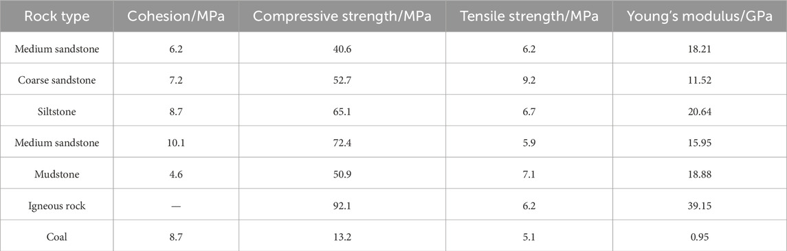
Table 1. Test results for compressive and tensile strength of roof rock.
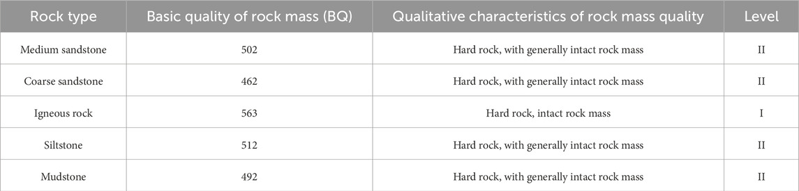
Table 2. Classification results of roof rock types.
3 Failure characteristics and deformation mechanisms of roadways
3.1 Characteristics of deformation and failure in roadway
To better analyses the deformation mechanism of the 5,230 auxiliary transport roadway, exploratory boreholes were drilled into the roadway roof and both sidewalls within the stable deformation section. The drill hole distribution is shown in Figure 2. A borehole inspection camera was employed to observe the development characteristics of fractures within the surrounding rock, thereby providing a theoretical foundation for studying tunnel support techniques. The borehole inspection results are shown in Figure 3. Based on the roof borehole inspection images, the degree of fissure development in the roof and both sidewalls of the 5,230 auxiliary transport roadway is summarized in Table 3.
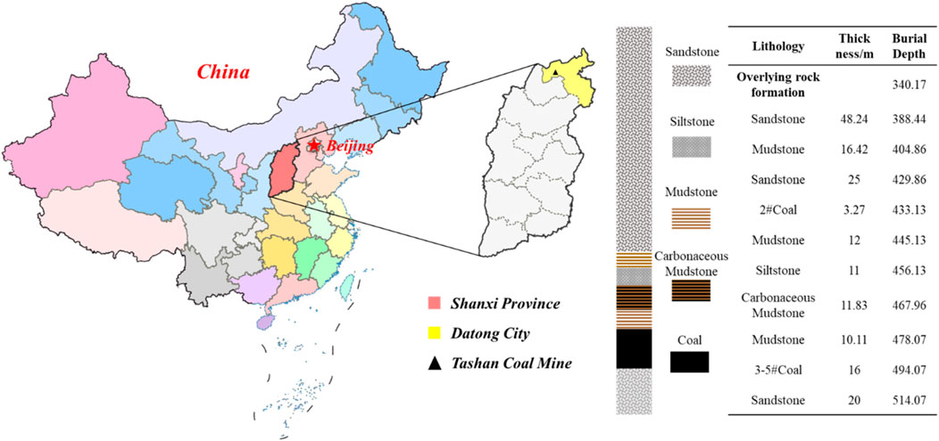
Figure 1. Geographical location of Tashan coal mine and lithology of roof and floor strata.

Figure 2. Drill hole layout diagram.
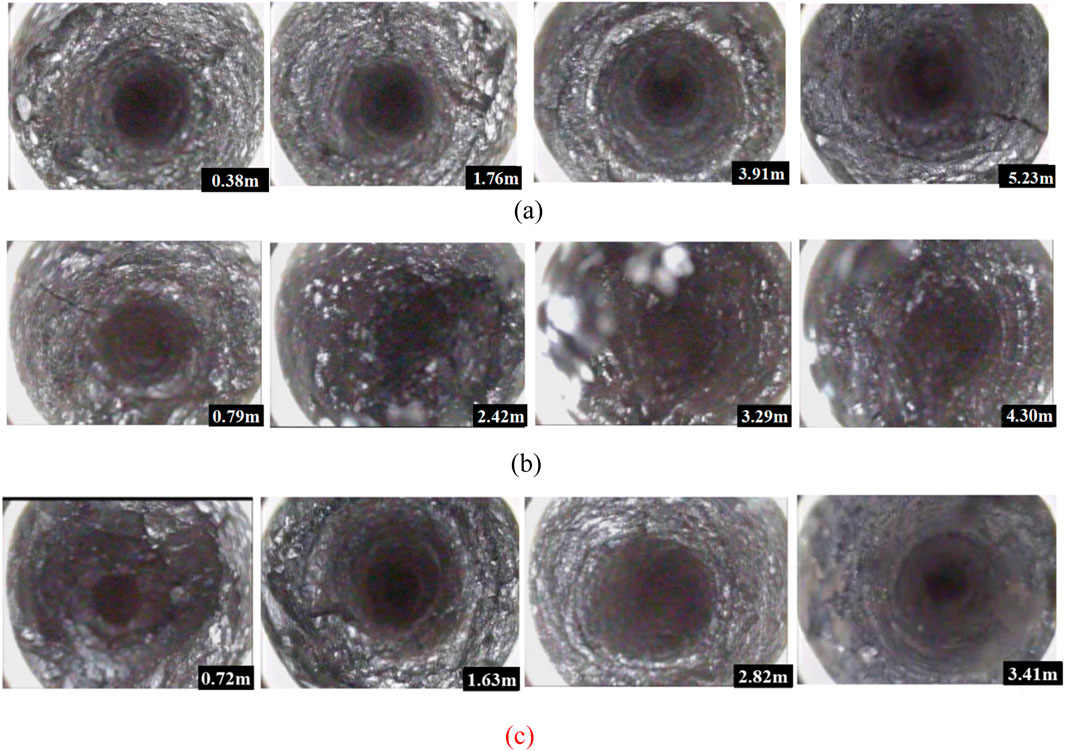
Figure 3. Drill hole view of the roadway surrounding rock. (a) Roof drill hole no. 1 inspection view. (b) Side view of drill hole no. 2 at the working face. (c) View of drill hole no. 3 in the coal pillar rib.
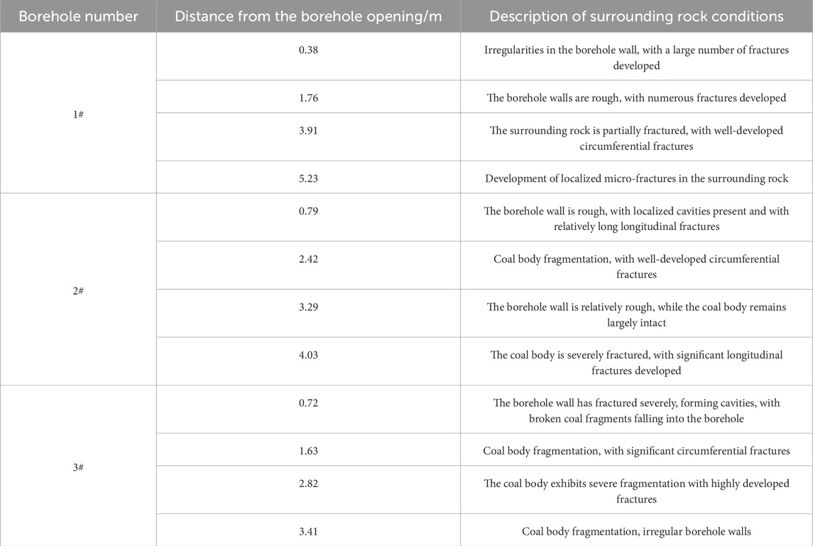
Table 3. Results of borehole inspection of roof.
The results from the borehole observations indicate that the 5,230 auxiliary transport tunnel has suffered severe instability and deformation due to repeated mining activities. The tunnel exhibits significant contraction deformation, with pronounced asymmetry, particularly in the coal pillar rib and roof on the open-pit side. Based on an analysis of the roadway’s surrounding rock mechanical characteristics and the actual production conditions of the mine, the primary causes of the instability and deformation in the 5,230 auxiliary transport roadway at Tashan Mine include: insufficient strength of the support structure, the influence of the hard hanging wall in the adjacent working face goaf, and the impact of repeated disturbances from the working face. Therefore, to achieve stability in Tashan Mine’s extra-thick coal seam mining roadways, it is essential to conduct in-depth research analysing the structural characteristics of roadway surrounding rock and the spatiotemporal evolution of stress-displacement under repeated disturbance. Regarding the lateral concentrated stresses caused by the hard hanging roof, research into roof cutting and pressure relief techniques for Tashan Mine’s hard roof strata is required. Concurrently, addressing the issues of inadequate support strength and severe deformation instability in the roadways, urgent research is required into enhanced support techniques for roadways in ultra-thick coal seam mining. This aims to improve the stability of the Tashan Mine’s roadways adjacent to the coal seam and ensure safe production in the mine.
3.2 Numerical simulation analysis of roadway deformation
This simulation employs the engineering context of the 8,228 and 8,230 longwall mining faces at Tashan Mine, utilizing the single-pass high-low roof caving method for the exceptionally thick No. 3-5 coal seams. Employing FLAC3D numerical simulation software, a computational model was established as depicted in Figure 4. FLAC3D can accurately simulate displacement changes at element nodes following model excavation and arrange displacement monitoring lines. The model dimensions are: strike direction (x) 350 m long, dip direction (y) 300 m long, and height (z) 100 m. Coal seams 3-5 exhibit an average dip angle of 2°, classifying them as near-horizontal formations. Given their minimal inclination, modelling treated them as horizontal strata. The average burial depth is approximately 440 m, with rock mass density set at 2,500 kg/m3 and lateral pressure coefficient at 1.2. Drawing upon prior experience, the Mohr-Coulomb constitutive model was employed for this simulation. The model’s base boundary was fixed, while equivalent loads were applied to the upper free boundary to simulate overburden pressure. Following stress equilibrium initialization, the working faces and haulage roadways were distributed according to actual engineering requirements.
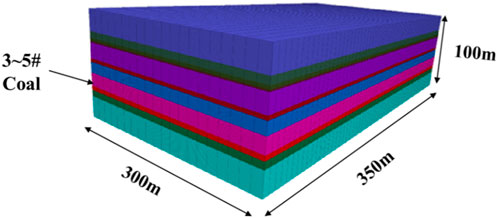
Figure 4. Numerical computation model.
Based on the actual production conditions of the 8,228 and 8,230 working faces at Tashan Coal Mine, and due to the pressing task of face succession, when excavation commenced on the 5,230 auxiliary haulage roadway, the adjacent 8,228 working face had not been fully reclaimed. Consequently, the pre-excavated forward section of the roadway was subject to repeated mining operations from the 8,228 working face. By the time the rear section was excavated, the 8,228 face had been fully reclaimed, and the roadway was advanced along the periphery of the 8,228 goaf.
Consequently, the excavation of the 5,230 auxiliary transport roadway can be divided into four distinct phases based on temporal and spatial relationships: excavation along solid coal seams, excavation affected by the primary mining impact of the 8,228 working face, excavation along the edge of the 8,228 goaf, and excavation affected by the secondary mining impact of the 8,330 working face, as illustrated in Figure 5.
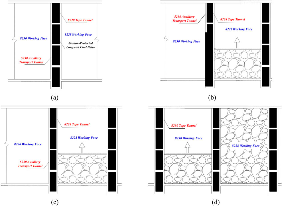
Figure 5. Spatiotemporal relationships at various stages of the roadway. (a) Excavation along solid coal. (b) Affected by the initial mining impact of the 8,228 working face. (c) Excavation along the edge of the goaf. (d) Secondary mining impact from the 8,230 working face.
Based on the above analysis, to investigate the stress and deformation evolution patterns of the surrounding rock throughout the entire service life of the 5,230 auxiliary transport roadway in the exceptionally thick coal seam at Tashan Mine, a model was first established. The 5,230 auxiliary transport tunnel was excavated 200 m along the Y-direction, with anchor bolts and cable support in accordance with engineering practice. This examined the impact of excavation through solid coal strata on the surrounding rock of the roadway. Subsequently, the 8,228 working face was reclaimed over 200 m in the opposite direction, to examine the impact of 8,228 working face mining on the roadway and coal pillars. Following stress equilibrium, 200 m of 8,230 working face mining was conducted to investigate the stress and deformation mechanisms of the roadway’s surrounding rock under repeated mining activities in a highly dynamic pressure roadway within an exceptionally thick coal seam. To mitigate boundary effects, 50 m boundary coal pillars were retained in both the X and Y directions during working face and roadway excavation.
The auxiliary haulage drift 5,230 has exhibited deformation and instability due to repeated mining activities, primarily manifested as rib bulging. This is particularly pronounced during mining operations in the adjacent 8,228 working face and during the current working face’s extraction, where significant changes in the drift’s surrounding rock have occurred. The displacement contour map and support deformation under repeated mining conditions are illustrated in Figure 6. Analysis of the diagram reveals substantial deformation in the coal pillar sidewall. During the mining operations of the 8,230 working face, the roadway deformation increased rapidly, with the rock bolts exhibiting a certain degree of bending deformation, thereby reducing the effectiveness of the support.
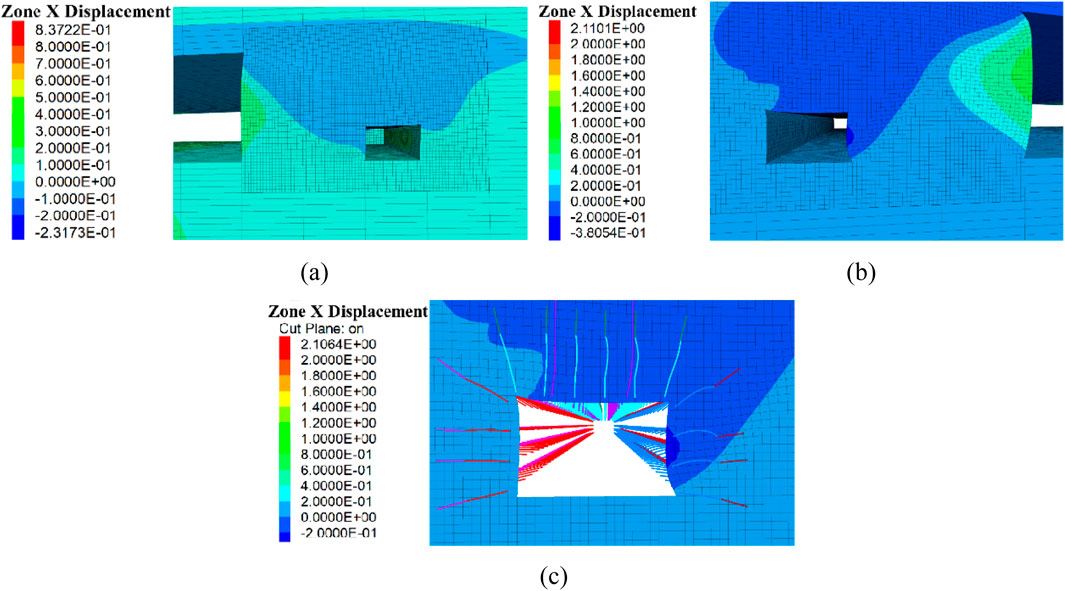
Figure 6. Deformation contour map of the 5,230 auxiliary transport roadway. (a) Mining impact on the 8,228 working face. (b) Repeated mining impact on the 8,230 working face. (c) Deformation of anchor rods (cables).
3.3 Deformation characteristics of roadways
3.3.1 Roof and floor
To further quantify the deformation of surrounding rock in roadways during different stages of mining disturbance, survey lines are laid out along the roadway alignment ahead of the working face. Data is extracted to analyses the deformation of the roadway roof, floor, and both side walls, thereby revealing the deformation patterns of surrounding rock throughout the entire service life of the roadway.
Figure 7a illustrates the variation in roof displacement deformation across different stages of the roadway. Analysis reveals that under the influence of disturbances at each stage, the deformation trends along the strike direction at various locations within the roadway roof exhibit consistent patterns. The roof deformation of the 5,230 auxiliary haulage roadway was minimal during its excavation phase, whereas the greatest vertical displacement occurred during the mining operations at the 8,230 working face. Figure 7b illustrates the variation in roadway floor displacement across different stages. The graph reveals that the maximum vertical displacement of the floor during the 8,230 working face mining operation was 95.28 mm, with the vertical displacement trend remaining largely consistent across all stages.
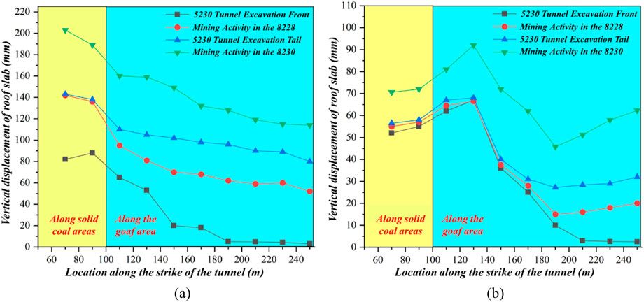
Figure 7. Vertical displacement of roof and floor in the 5,230 auxiliary transport roadway. (a) Vertical displacement of the roof. (b) Vertical displacement of the floor.
To investigate the impact of adjacent 8,228 working face mining on the excavated roadway area, the 5,230 auxiliary transport roadway was advanced 50 m along the Y-direction over a 50 m–100 m section. Analysis of the figures reveals that During the excavation of this roadway, the advance roadway excavation zone—specifically the section along the strike position between 100 and 120 m—was affected by the excavation of this roadway, resulting in a significant increase in roof subsidence reaching 50 mm. Meanwhile, the undeveloped rear section of the roadway-between 120 and 250 m along the Y-direction—exhibited minimal deformation of the roadway roof due to the excavation of this roadway, with relatively small deformation values. The deformation in this area is primarily influenced by the mining activities of the 8,228 and 8,230 working faces. During the mining of the adjacent 8,228 working face, the section between 50 m and 100 m along the Y-direction (already excavated roadway area) experienced a marked increase in roof deformation, reaching 60 mm, due to the impact of the neighboring working face’s mining operations. During the 8,230 working face extraction in this section, the supporting coal pillars within the section were subjected to high concentrated stresses, making them prone to instability and reduced load-bearing capacity. The forward section of the roadway was repeatedly disturbed by mining activities, with maximum roof subsidence exceeding 200 mm. The deformation trends in the rear section of the roadway—excavated along the edge of the goaf—remained largely consistent across all phases. When subjected to mining activity from the 8,228 working face, the vertical displacement of the roof in this rear section was approximately 50 mm. However, when this same area was subsequently impacted by the mining operations of the 8,230 working face, the vertical roof displacement increased to 150 mm. Consequently, the vertical displacement of the roadway roof is primarily influenced by the mining activities of the working face. Furthermore, under the repeated mining impact of the 8,230 working face, the deformation of the roadway roof exhibits a more pronounced increase.
3.3.2 Both sides of the roadway
As illustrated in Figure 8a, the horizontal displacement variations of the tunnel rib under repeated mining activities are depicted through survey lines laid out ahead of the working face. Analysis reveals that during both tunnel excavation and the mining phase of the 8,228 working face, the overall displacement of the rib remained minimal, below 30 mm, with a largely consistent trend. During the 8,230 working face mining phase, influenced by advance mining pressure, the horizontal displacement of the working face sidewall rapidly increased, reaching a maximum of 100 mm. The impact of the 8,230 working face mining on the sidewall was greater than that on the roadway roof and floor.
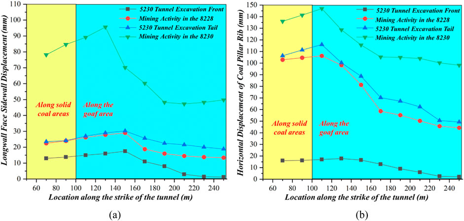
Figure 8. Horizontal Displacement of Both Ribs in the 5,230 Auxiliary Transport Roadway. (a) Horizontal displacement of the working face sidewall. (b) Horizontal displacement of the coal pillar sidewall.
Figure 8b illustrates the horizontal displacement of the roadway coal pillar sidewall at different positions along the roadway strike, measured via survey lines laid out in advance of the working face under repeated mining operations. Analysis reveals that, due to mining disturbance, the surrounding rock deformation of the roadway coal pillar sidewall exceeds that of the working face sidewall, with maximum deformation reaching 150 mm across all phases. Furthermore, the displacement variation of the roadway coal pillar sidewall was significant when subjected to mining activities from both the 8,228 and 8,230 working faces. However, when advancing along the edge of the solid coal body or along the edge of the goaf, the displacement variation of the coal pillar sidewall remained relatively minor. Following repeated impacts from excavation along the solid coal edge and adjacent mining activities at the 8,228 working face, the coal pillars along the roadway’s coal pillar side had already undergone substantial deformation, resulting in reduced load-bearing capacity. When mining continued at the 8,230 working face, the forward section of the roadway again experienced repeated mining impacts, causing the coal pillars to become fundamentally deformed and unstable. The rear section of the roadway, having experienced minimal disturbance from the 8,228 working face earlier, exhibited limited deformation of the coal pillar walls. However, under the pressure from the 8,230 working face extraction, deformation in this rear section also increased rapidly, reaching 110 mm. Consequently, the 5,230 auxiliary transport roadway, subjected to repeated extraction disturbances, has experienced substantial overall deformation of its coal pillar walls, necessitating enhanced maintenance measures for these walls.
In summary, the thick coal seams and hard roof strata at Tashan Mine result in extensive goaf spaces and difficult roof collapse. This creates a cantilevered roof structure that concentrates lateral stresses on the sectional coal pillars. Consequently, the roadway’s coal pillar walls suffer severe deformation with asymmetric deformation occurring on both sides. Enhanced support measures must therefore be implemented for the roadway’s coal pillar walls.
4 Hard roof cutting and roof pressure relief control technology
4.1 Analysis of the mechanism of roof cutting and pressure relief
Due to the hardness and considerable thickness of the roof strata in the No. 3 to No. 5 coal seams at Tashan Mine, roof collapse during longwall mining is difficult to achieve promptly. This results in extensive suspended roof areas within the goaf, characterized by long collapse strides and pronounced manifestations of pressure. As analyzed in Chapter 3, the cantilevered masonry beam structure formed by the roof collapse in the goaf bears the load of the overlying strata above the suspended roof. This load is further transferred through the thick, hard roof to the coal pillars above adjacent working faces and sectional support roadways. This causes a degree of stress concentration above the sectional support roadways’ coal pillars, leading to pillar deformation and instability. Consequently, this further induces deformation and failure in the mining roadways of neighboring working faces. Therefore, to investigate the mechanism of roof cutting and pressure relief, it is necessary to analyses the extent to which the load from the overlying strata borne by the thick, hard roof affects the lateral section guard roadway coal pillar and the adjacent working face mining roadway before and after roof cutting. This entails determining the magnitude of stress experienced by the section guard roadway coal pillar before and after roof cutting. To facilitate the determination of stress levels on the sectional roadway pillars before and after roof cutting, a load estimation method is employed to calculate the loads borne by the pillars.
The load estimation method serves as a simplified model for calculating the magnitude of loads borne by the roof in mining areas. This approach does not account for the differing migration characteristics of overlying strata affecting the coal pillar, nor does it consider the influence of the damaged peripheral zone on the pillar’s interior. Nevertheless, owing to its relatively straightforward principles and its ability to provide an intuitive explanation of mining engineering issues, it finds widespread application. Based on relevant research conclusions, the primary principle underlying the load estimation method’s calculation of loads above coal pillars is as follows: the main loads borne by sectional coal pillars comprise those from the overlying strata above the pillar and the overlying strata supported by the suspended roof in the goaf. Given a fixed bearing area, the magnitude of these loads represents the internal stress within the coal pillar. The calculation principle is illustrated in Figure 9.
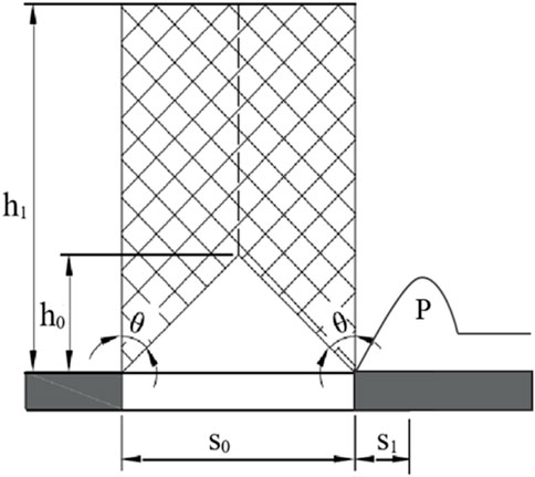
Figure 9. Load estimation algorithm computational model.
From Figure 9, the load P exerted upon the coal body above is Equation 1 (Huang, 2025):
In the formula, S0 denotes the width of the goaf in meters; S1 denotes the width of the pillar section in meters; h1 denotes the height of the overlying strata in meters; θ denotes the collapse angle of the overlying strata in degrees; P denotes the average unit weight of the overlying strata in N/m3.
Based on the structural characteristics of the roof overburden in the goaf following face extraction, a load calculation model for the coal pillar prior to roof cutting and pressure relief is established, as illustrated in Figure 10.
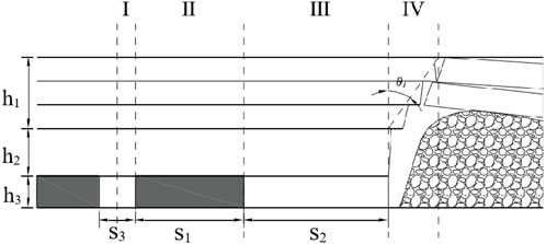
Figure 10. Load bearing by coal pillars prior to roof cutting and pressure relief.
In the diagram, S1 denotes the width of the sectional coal pillar in meters; S2 denotes the width of the hanging roof in meters; S3 denotes the width of the roadway in meters; h1 denotes the height of the overlying strata on the thick, hard roof in meters; h2 denotes the height of the thick, hard roof in meters; h3 denotes the thickness of the coal seam in meters. Where zone I bears the load from the overlying strata of the mining roadway adjacent to the working face; Zone II bears the load from the overlying strata of the sectional coal pillar; Zone III bears the load from the overlying strata of the thick, hard roof overhanging the goaf; Zone IV bears the load from the pre-decompression overhanging roof mass. Based on the principles of load estimation methods, the magnitude of loads in each zone is as follows Equation 2:
In the formula, θtmax denotes the tensile strength of thick, hard roof rock, N/m2; θ1 represent the roof collapse angle of the goaf, °.
Therefore, prior to implementing roof cutting and pressure relief on the thick, hard roof, the total load P borne by the S1 section of the sectional pillar is Equation 3:
The average stress σ1 of the coal pillars in the sectional support roadway is thus determined as Equation 4:
Upon cutting through the thick, hard roof overburden, the integrity of the solid roof in the goaf is compromised, diminishing its load-bearing capacity. Concurrently, the strata above the roof undergo blasting effects, reducing their strength. Consequently, the overlying strata above the roof will slide along the roof-cutting line into the goaf. Consequently, roof cutting and pressure relief technology severed the connection between the overlying strata and the coal pillar, mitigating stress concentration within the pillar. Following the stabilization of the collapsed waste rock in the goaf, the roof collapse angle at this stage was. The load-bearing conditions above the coal pillar at this point are illustrated in Figure 11.
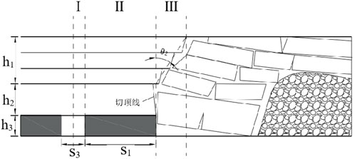
Figure 11. Load-bearing capacity of coal pillars after roof caving and pressure relief.
As shown in Figure 11, after capping and relieving pressure, the load borne by the sectional coal pillar is redistributed across three zones: Zone I bears the load from the overlying strata of the adjacent working face’s mining roadway; Zone II bears the load from the overlying strata of the sectional coal pillar itself; Zone III bears the load from the overlying strata of the thick, hard roof’s cantilever section in the goaf. Based on the principles of load estimation methods, the magnitude of loads for each zone is calculated as follows Equation 5:
Therefore, following the caving of the thick, hard roof to relieve pressure, the total load P′ borne by the S1 section of the sectional coal pillar is Equation 6:
The average stress σ2 of the coal pillars in the sectional support roadway is thus determined as Equation 7:
Therefore, the change in load ΔP borne by the coal pillars in the sectional support roadway before and after roof cutting and pressure relief is:
In actual production processes, the magnitude of the roof collapse angle in the goaf is influenced by the geological structure of the coal seam, the physical and mechanical properties of coal and rock, and the mining methods employed at the working face. Consequently, since the overlying strata and coal seam geological structure remain consistent before and after roof caving, the θ1 = θ2 treatment may be applied. Substituting into Equation 8 yields the change in load ΔP borne by the coal pillar before and after roof caving Equation 9:
The stress change Δσ is defined as:
Analysis of Equation 10 reveals that γS2h2 represents the load borne by the thick, hard roof cantilever beam itself, while γS2h1 denotes the load exerted by the overlying strata upon the thick, hard roof. Consequently, the reduction in load before and after roof cutting and pressure relief equals the combined load of the thick, hard roof itself and its overlying strata. Consequently, implementing roof cutting and pressure relief techniques for exceptionally thick coal seams with rigid roof strata can effectively reduce the magnitude of loads borne by the supporting pillars in adjacent sections. The primary mechanism involves: Performing directional blasting to cut the roof in the rigid overhanging section of the goaf, thereby disrupting the roof’s integrity and reducing the strength of the overlying strata; enabling the cantilevered section of the thick, hard roof to collapse promptly and effectively into the goaf. This reduces the area of the suspended roof zone within the goaf, severing the connection between the suspended roof in the goaf and the supporting pillar in the roadway. Consequently, the load borne by the section pillar from the suspended roof section and the load borne by the overlying strata on the suspended roof section are both reduced. This enhances the stability of the supporting pillar in the roadway, thereby further ensuring the stability of the roadways for adjacent working faces.
4.2 Numerical simulation analysis of roof cutting for pressure relief
This simulation employs the UDEC discrete element numerical simulation software, which effectively models rock mass collapse and displacement while accurately depicting the stress state of the surrounding rock within the mining area. For computational convenience, the model is scaled down proportionally based on the mining conditions at Tashan Coal Mine, without compromising simulation accuracy. The designed model dimensions are 120 m in width and 75 m in height. The 8,230 working face goaf spans 100 m in width with a mining height of 14.5 m. The sectional support roadway coal pillar width is 8 m, while the 5,230 auxiliary transport roadway dimensions are 5,000 × 3000 mm. Simultaneously, horizontal constraints were applied to the left and right boundaries of the model, vertical constraints to the base, and vertical stress to the top to simulate overburden pressure. The model configuration is illustrated in Figure 12.
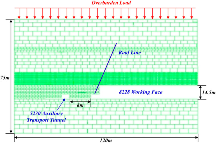
Figure 12. Schematic diagram of the model.
Based on the aforementioned research analysis, stress evolution contour plots for the pillar in the sectional support roadway and displacement contour plots for the overburden in the goaf were investigated under different roof caving angles and roof caving heights. When varying the roof caving angle, and in accordance with the theoretical analysis presented earlier, the roof caving height was fixed at 36 m. Following the principle of equal-interval control for variables, four simulation scenarios were designed with roof caving angles of 0°, 11°, 22°, and 33°. Similarly, when varying the capping height, the capping angle was fixed at 13°, with simulation schemes designed for four capping heights: 10 m, 23 m, 36 m, and 48 m. Concurrently, stress data was extracted by deploying measuring lines within the sectional coal pillar. Through quantitative analysis of internal pillar stresses under different capping parameters, the stress-relief efficacy of various capping configurations was precisely evaluated.
4.3 The effect of different cutting roof parameters on pressure relief performance
4.3.1 Different cutting roof heights
Figure 13 presents a contour plot illustrating the displacement evolution of the roof overburden in the goaf at different caving heights when the caving angle is 11°. Analysis reveals that following roof cutting roof to relieve pressure, key blocks slide along the cutting roof line towards the goaf. At cutting roof heights of 23 m, 36 m, and 48 m respectively, the collapse and migration patterns of the roof overburden remain largely consistent, with the cutting roof damage zone developing upwards as a whole. Furthermore, the roof block displacement is minimal at a cutting roof height of 10 m. This is primarily due to the presence of a 15 m-thick overlying fine sandstone roof above the coal seam. At this height, the thick, hard overlying roof remains largely intact, resulting in poor cutting roof effectiveness. Beyond a cutting roof height of 23 m, the displacement of the roof increased markedly. However, as the cutting roof height increased further, the rate of displacement increase for the roof became relatively small, with the displacement behavior of the overburden remaining similar.
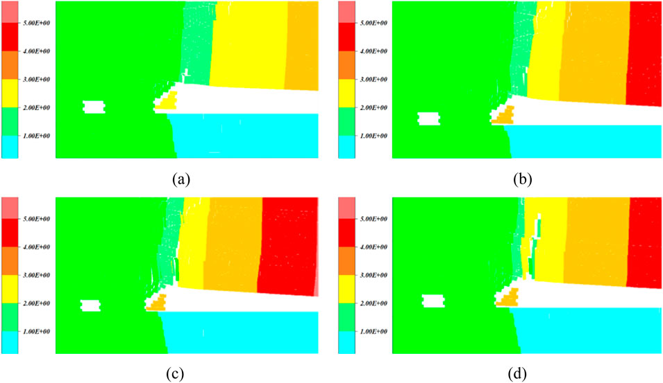
Figure 13. Displacement contour map of overlying rock at different cutting roof heights. (a) 10 m. (b) 23 m. (c) 36 m. (d) 48 m.
Figure 14 depicts the stress evolution contour map of the roof overburden in the goaf at different roof caving heights when the roof caving angle is 11°. Analysis reveals that when the roof caving height is 10 m and 23 m, after implementing cutting roof to relieve pressure, the stress values in the surrounding rock and the coal pillar of the sectional support roadway in the 5,230 auxiliary transport roadway remain relatively high. When the cutting roof height increased to 36 m and 48 m, the roof stress distribution remained largely consistent. At these heights, the 5,230 auxiliary transport roadway was clearly within a low-stress zone, and the stress values in the sectional support roadway coal pillar also decreased significantly.
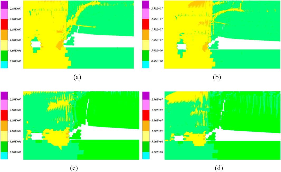
Figure 14. Stress contour plots for different cutting roof heights. (a) 10 m. (b) 23 m. (c) 36 m. (d) 48 m.
Analysis of Figure 15 reveals that when the roof caving height is 10 m, 23 m, 36 m and 48 m respectively, the peak stresses within the coal pillar are 14.70 MPa, 12.60 MPa, 9.2 MPa and 9.8 MPa respectively. The minimum peak stress occurs at a cutting roof height of 36 m. Analysis indicates that as the cutting roof height increases, the peak stress within the coal pillar decreases. However, beyond a certain cutting roof height, the peak stress within the coal pillar begins to increase, indicating a deterioration in the effectiveness of cutting roof. Furthermore, when the cutting roof height increased from 10 m to 48 m, the most significant stress changes and reductions occurred within the 3 m zone adjacent to the goaf. Stress variations in the support pillars along the 5,230 auxiliary transport roadway were comparatively minor. Overall, post-cutting roof, stress levels in pillars adjacent to the goaf exceeded those near the roadway. This disparity was particularly pronounced at a 10 m cutting roof height, primarily because the thick, rigid roof had not yet been fully fractured. Allowing concentrated loads on the hanging roof section to transfer onto the sectional roadway pillar. Consequently, the cutting roof effect was diminished.
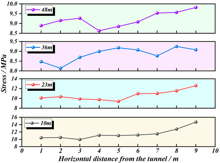
Figure 15. Stress variation curves for support pillars in roadways at different roof cutting heights.
Based on the above analysis, a reasonable cutting roof height should effectively fracture the hard suspended roof of the coal seam, enabling its smooth collapse into the goaf. This prevents the transfer of overburden loads from the roof onto the sectional roadway coal pillar and adjacent working face roadways. Combining numerical simulation results, when the cutting roof height is 36 m, the peak stress within the coal pillar is minimized at 9.4 MPa. Therefore, the cutting roof height for pressure relief in the exceptionally thick coal seams at Tashan Mine is determined to be 36 m.
4.3.2 Different cutting roof angles
Figure 16 depicts the evolution of roof displacement in the goaf under varying roof cutting roof angles at a cutting roof height of 36 m. Analysis reveals that following cutting roof to relieve pressure, the suspended roof within the goaf exhibits a degree of bending and subsidence. The cutting roof blast disrupts the structure of the thick, hard overlying roof. At varying roof cutting angles, the roof strata within the cutting height range exhibit sliding along the cutting line, significantly enhancing the stability of the coal pillar and roadways. Moreover, when the cutting roof angle is 0°, the frictional resistance between rock masses on either side of the cutting line is low. Under gravitational force, the roof strata in the goaf tend to slide downward. The direct roof cantilever section essentially slides along the edge of the coal pillar into the goaf. Consequently, the load borne by the pillar in the sectional support roadway and the upper section of the adjacent working face’s mining roadway is unaffected by the overburden load from the goaf roof. When the cutting roof angle increases to 33°, the friction resistance between rock masses on either side of the cutting roof line remains low. However, relative displacement between these rock masses becomes more difficult. Consequently, the suspended roof in the goaf struggles to slide effectively into the goaf area. The load from the overlying strata on the goaf roof strata can still be transferred to the section guard roadway coal pillar above. Thus, the cutting roof pressure-relief effect is diminished.
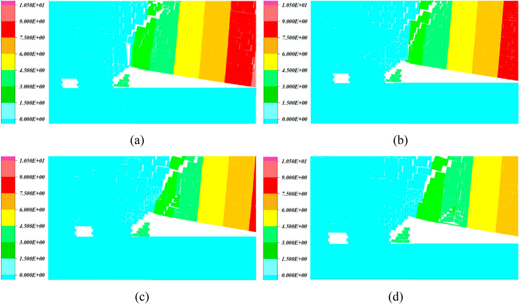
Figure 16. Displacement contour map for different cutting roof angles. (a) 0°. (b) 11°. (c) 22°. (d) 33°.
Figure 17 depicts the stress evolution contour map of the roof overburden in the goaf at a roof cutting height of 36 m under different roof cutting angles. Analysis of the figure reveals that the extent of the stress concentration zones remains largely consistent across varying roof cutting angles, situated near the roof cutting line and along its extension. As the cutting roof angle increases from 0° to 33°, the extent of the stress concentration zone near the cutting roof line progressively enlarges and shifts towards the vicinity above the adjacent working face’s longwall roadway. Consequently, stress levels above the coal pillar and longwall roadway gradually increase with greater cutting roof angles.
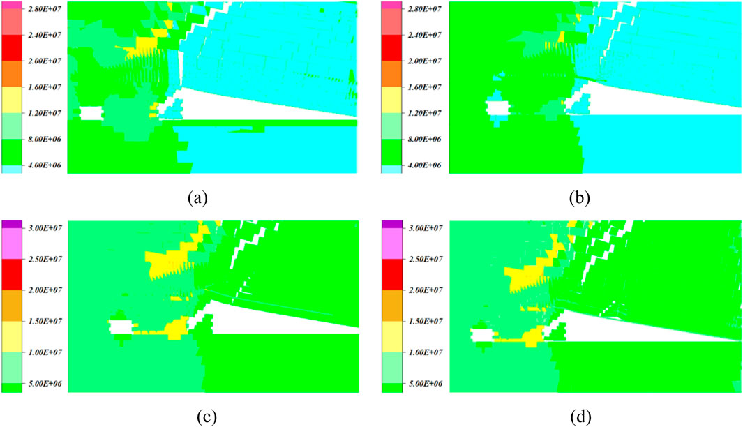
Figure 17. Stress contour map for different cutting roof angles. (a) 0°. (b) 11°. (c) 22°. (d) 33°.
To further quantify the cutting roof effect under varying cutting roof angles, data was extracted via survey lines. The internal stresses within the sectional roadway pillars for different cutting roof angles are presented in Figure 18.
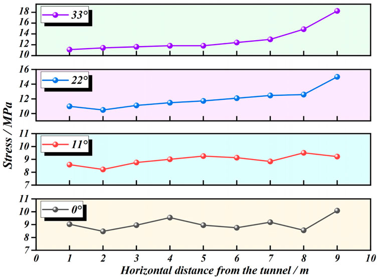
Figure 18. Stress variation curves of support pillars in roadways with different roof cutting angles.
Analysis of Figure 18 reveals that stress values within the coal pillar progressively increase with greater roof cutting angles. At a roof cutting angle of 0°, stress near the coal pillar position of the 8,228 working face measures 10.1 MPa. When the roof cutting angle increases to 33°, stress rises to 18.1 MPa. The primary reason is that at smaller cutting roof angles, the overburden in the goaf exhibits a pronounced tendency to slide downwards along the cutting roof line. However, when the cutting roof angle increases to 33°, the frictional resistance of the rock masses on both sides near the cutting roof line becomes significant. This makes it relatively difficult for the overburden to slide into the goaf, maintaining a stable cantilever beam structure in the goaf roof.
Based on the above analysis, different cutting roof angles exert varying effects on roof cutting pressure relief. When the cutting roof angle is large, the roof structure of the goaf remains relatively intact. However, due to substantial friction forces persisting on both sides of the cutting roof line, the hard hanging roof cannot effectively slide into the goaf. Consequently, it continues to bear high loads, which are transferred via the cantilever beam structure to the coal pillars supporting the sectional guard roadway. This compromises the stability of the guard roadway pillars and further undermines the stability of the mining roadways. When the cutting roof angle is relatively small, it effectively severs the connection between the hard hanging roof of the goaf and the sectional roadway support pillar. The hanging roof of the goaf then collapses smoothly into the goaf interior, achieving a more favorable cutting roof and pressure relief effect. Based on numerical simulation results, when the height of the cutting roof is 36 m and the cutting roof angle is 11°, the peak stress within the coal pillar is minimized at 10.1 MPa. Therefore, the cutting roof angle for pressure relief in the exceptionally thick coal seam at Tashan Mine is determined to be 11°.
5 Grouting and anchor cable reinforcement technology for roadway support
As demonstrated by the aforementioned analysis of the rock mass structure in the 5,230 auxiliary haulage drift and the stress-deformation evolution patterns under repeated mining activities, the integrity and strength of the drift have been compromised to a certain extent due to the disturbance caused by intense dynamic pressure stresses under repeated mining operations. This has resulted in difficulties in maintaining the stability of the drift’s surrounding rock. Particularly during the mining of the 8,230 working face, the roadway exhibited instability and deformation, with severe deformation occurring in the coal pillar sidewall area, due to the disturbance caused by advance mining stresses from the working face. Although supplementary measures such as installing extended anchor cables have been implemented, these retrofitted reinforcements prove insufficient for controlling surrounding rock stability during subsequent mining operations in this face. Based on the foregoing analysis, the design proposes employing grout-injected anchor cable reinforcement technology for the coal pillar sidewall of the 5,230 auxiliary transport roadway in Tashan Coal Mine’s extra-thick coal seam. This approach aims to enhance surrounding rock strength, restore its integrity, improve coal pillar stability, and thereby further ensure roadway stability.
Grout-filled anchor support technology integrates anchor support with grouting techniques. Grout is injected through hollow anchors into the surrounding rock, where it diffuses into deeper strata. Upon entering rock fractures, the grout undergoes a solidification reaction, bonding with the surrounding rock. This process consolidates fragmented zones in the near-surface rock mass into a cohesive, integral structure, thereby enhancing rock integrity. Further strengthening its physical and mechanical properties and enhancing the support structure’s performance.
To further determine the key technical parameters for hollow grouting cable support at Tashan Mine, numerical simulations were conducted on grouting pressure, cable spacing, and cable length to identify optimal grouting parameters. These simulations, based on the diffusion radius of grout within the rock mass, varied the mechanical properties of rock in different surrounding areas to model the support effectiveness under various support parameters.
5.1 Key parameters for grouting anchor cables
5.1.1 Determination of grouting pressure
Numerical computational models were established to simulate the horizontal displacement characteristics of the 5,230 auxiliary haulage roadway under grouting pressures of 1 MPa, 2 MPa, and 3 MPa, as illustrated in Figure 19.
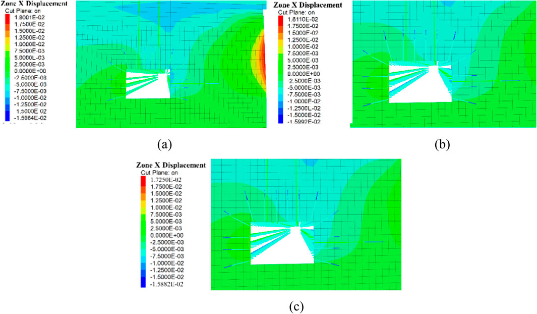
Figure 19. Characteristics of horizontal displacement variation in the 5,230 auxiliary transport roadway under different grouting pressures. (a) P = 1 MPa, R = 1 m. (b) P = 2 MPa, R = 1.5 m. (c) P = 3 MPa, R = 2 m.
Further surveying lines were deployed to extract data, yielding the surrounding rock deformation patterns for different grouting pressures in the roadway, as shown in Table 4. Analysis of the table indicates that as grouting pressure increases, the deformation of the roadway’s surrounding rock decreases, with the most effective control observed for the roof and coal pillar side walls. Primarily because grouting reinforcement of the coal pillar sidewalls enhances the pillar’s inherent stability. Furthermore, increased grouting pressure expands the dispersion range of grout within rock fractures, thereby enlarging the reinforced area. Based on this analysis, the grouting anchor cable pressure was determined to be 3 MPa.
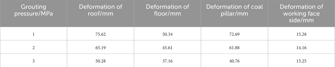
Table 4. Deformation of surrounding rock under different grouting pressures.
5.1.2 Determination of grouting anchor cable spacing
The grouting pressure was set at 3 MPa to simulate the horizontal displacement deformation characteristics of the 5,230 auxiliary transport roadway when the spacing of the grouting anchor cables was 0 m, 1 m, and 0.75 m respectively. The corresponding grouting anchor cable densities were 1 cable per row, 2 cables per row, and 3 cables per row. The simulation results for the deformation patterns of the roadway surrounding rock are shown in Figure 20.
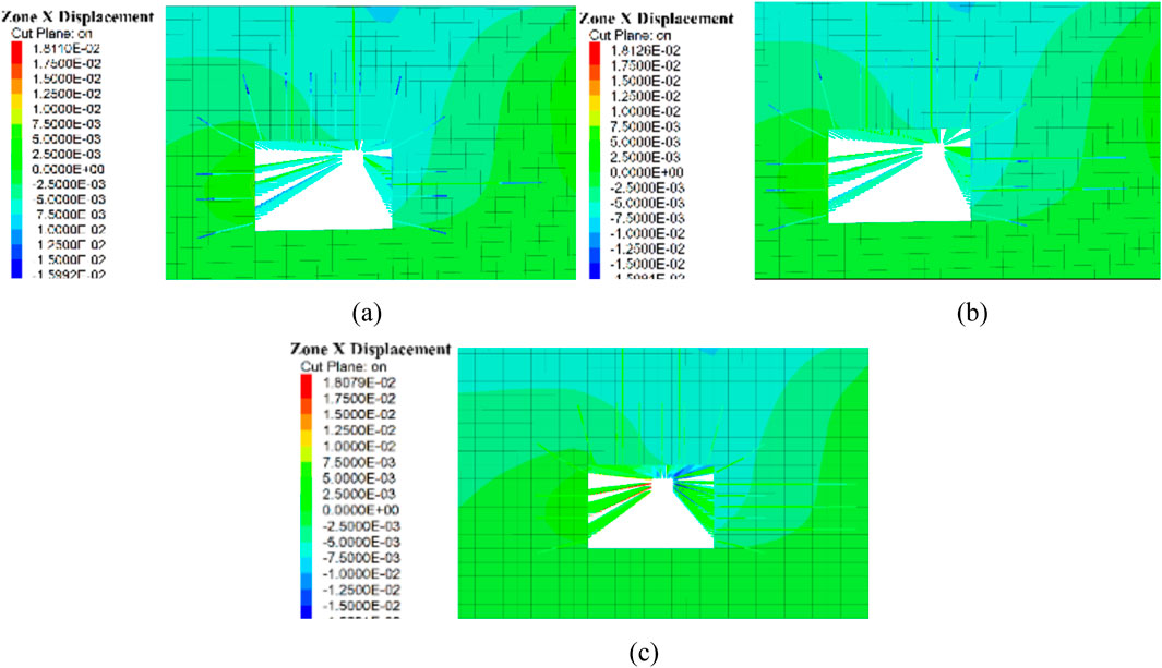
Figure 20. Characteristics of horizontal displacement variation in the 5,230 auxiliary transport tunnel at different grouting anchor cable spacings. (a) n = 1. (b). n = 2. (c) n = 3.
Further layout of survey lines to extract data yielded the deformation characteristics of the roadway surrounding rock under different grouting anchor cable spacings, as shown in Table 5. Analysis of the table indicates that as support density increases, the area of grout diffusion expands significantly, substantially broadening the range of improved support strength for the coal pillar. This enhances the pillar’s inherent load-bearing capacity and effectively controls its stability. When the grouting anchor cable density was increased to three cables per row, the control effect on the 5,230 auxiliary transport roadway’s surrounding rock proved negligible. Therefore, considering both manpower and material resources, the optimal grouting anchor cable density was determined to be two cables per row.
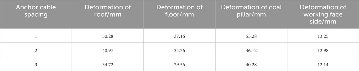
Table 5. Deformation of surrounding rock under different grouting anchor cable spacing.
5.1.3 Determination of grouting anchor cable length
Based on the reinforcement principle of grouted anchor cables, these cables exert a full-length anchoring effect on the surrounding rock. Consequently, the anchoring efficacy varies with the length of the grouted anchor cables. Simulations were conducted for grouting pressures of 3 MPa and anchor cable densities of two cables per row. The deformation patterns of the 5,230 auxiliary transport roadway’s surrounding rock were modelled for anchor cable lengths of 4.5 m, 5.5 m, and 6.5 m, as illustrated in Figure 21.
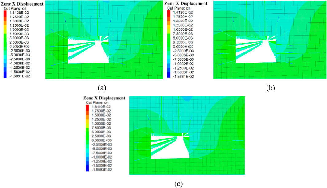
Figure 21. Characteristics of horizontal displacement variation in 5,230 auxiliary transport roadway at different grouting anchor cable lengths. (a) L = 4.5 m. (b) L = 5.5 m. (c) n = 6.5 m.
Further surveying lines were deployed to extract data, yielding the deformation characteristics of the roadway surrounding rock under different grouting anchor cable lengths as shown in Table 6. Analysis of the table indicates that when the grouting anchor cable length increased from 4.5 m to 5.5 m, the cables effectively controlled the deformation of the coal pillar sidewall, while also reducing roof deformation. Their impact on the roadway floor and working face coal sidewall deformation was relatively minor. However, extending the grouting anchor cable from 5.5 m to 6.5 m yielded relatively minor additional benefits for roadway rock mass control. This is because increased length brings the anchor cable driving depth closer to the 8,228 working face side, where the coal pillar is more fragmented, leading to poorer anchoring performance. Moreover, increasing the length of grout-filled anchor cables would also raise production costs. Therefore, after comprehensive consideration, the length of grout-filled anchor cables is set at 5.5 m.
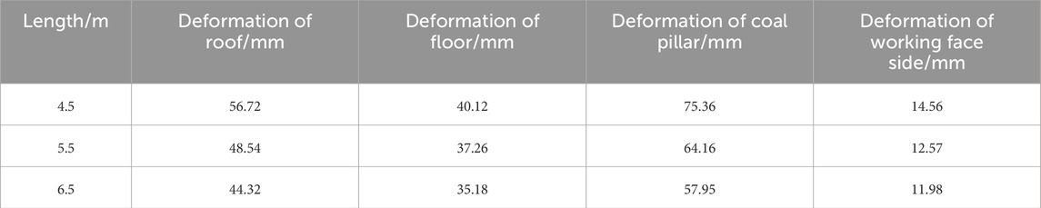
Table 6. Deformation of surrounding rock under different grouting anchor cable length.
5.2 On-site testing
To ensure the effectiveness of roadway support, an industrial trial was conducted in a selected test section underground. Simultaneously, monitoring points were deployed to assess the stress state of the rock bolts (cables) and the deformation of the roadway crown, thereby evaluating the support performance and providing a basis for further optimization of the support scheme.
5.2.1 Bolt and cable load monitoring
When the surrounding rock in a roadway deforms excessively, the support structure loses its effectiveness, and the load-bearing capacity of the rock bolts (cables) diminishes. Therefore, by monitoring the stress state of the anchor bolts (cables), one can determine whether they are providing support, thereby assessing the stability of the roadway. To this end, a set of anchor bolt (cable) stress monitoring stations was installed at 50-m intervals along the strike of the 5,230 auxiliary transport roadway. The changes in stress on the anchor bolts (cables) during the mining of the 8,230 working face are shown in Figure 22.
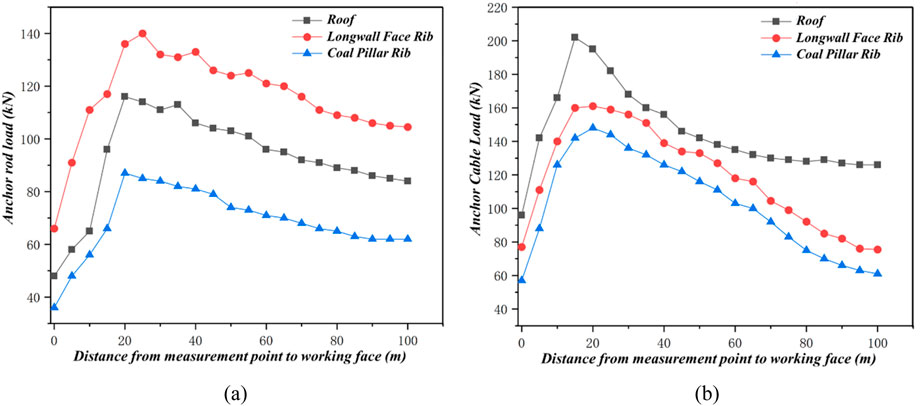
Figure 22. Loading of bolts (cables) during mining operations at the 8,230 working face. (a) Load conditions on anchor bolts. (b) Load conditions on anchor cables.
Analysis of the graph indicates that within the 20–100 m zone from the measurement point to the working face, the stress on the rock bolts (cables) gradually diminishes as distance from the face increases, with the rate of decrease slowing progressively. That is, the further from the face, the lesser the influence of advance mining stress from the working face. When the 8,230 working face advances to within less than 20 m of the monitoring points, the force on the rock bolts (cables) decreases rapidly. This is primarily due to the significant influence of advance mining stress in this zone, coupled with the highly developed fractures in the surrounding rock of the roadway, which reduces the supporting effectiveness of the rock bolts (cables).
5.2.2 Deformation in roadway surrounding rock
To provide a more intuitive representation of roadway support effectiveness, a cross-section sampling method was employed underground. Monitoring points were arranged at 50-m intervals along the roadway alignment to track deformation of the roof and sidewall rock masses in the 5,230 auxiliary transport roadway during the 8,230 working face extraction phase, as illustrated in Figure 23.
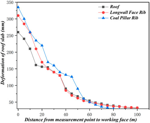
Figure 23. Deformation of surrounding rock during mining operations at the 8,230 working face.
Analysis of the diagram reveals that within the 60–100 m zone from the measurement point to the working face, the deformation of the roadway surrounding rock gradually diminishes with increasing distance from the working face, ultimately stabilizing. That is to say, the further the distance from the working face, the lesser the influence of advance mining stresses from the working face. When the 8,230 working face advanced to within less than 60 m of the monitoring points, the deformation of the roadway surrounding rock increased rapidly as the working face drew nearer. The maximum deformation recorded was 262 mm for the working face roof, 311 mm for the working face longwall pillar side, and 328 mm for the pillar side. The coal pillar sidewall exhibited the greatest deformation in the roadway. Nevertheless, the roadway rock mass deformation remained within parameters acceptable for safe mine operations. The roadway support system demonstrated relatively effective performance, thereby ensuring the continuity of mine production.
6 Conclusion
1. Mechanical property testing confirmed that the roof of the 3-5 coal seam consists predominantly of Class II or higher hard rock, exhibiting strong self-supporting capacity but prone to extensive suspended roof formation. Analysis of borehole observations and on-site rock mass deformation revealed that the primary cause of severe asymmetric deformation in the 5,230 roadway stems from the combined effects of concentrated stresses generated by lateral suspended roof in the upper section’s goaf and insufficient original support strength.
2. FLAC3D simulation analysis of roadway deformation patterns under varying mining phases indicates that rock mass displacement increases with mining cycles. Particularly significant horizontal displacement occurs at the roadway coal pillar sidewall, exhibiting the most severe damage. Angular stress concentration is pronounced at both roadway sidewalls, with rock mass deformation—especially asymmetric deformation at the coal pillar sidewall—escalating sharply with mining cycles.
3. To address lateral overburden suspension issues in hard roof conditions, cutting roof and pressure relief technology was proposed. A sectional coal pillar mechanical model was established based on load estimation, theoretically analyzing the mechanism of hard roof pressure relief through cutting roof. Key cutting roof parameters were optimized using UDEC numerical simulation, determining the optimal cutting roof height as 36 m and the optimal cutting roof angle as 11°.
4. For exceptionally thick coal seams with hard roof conditions, the “hollow grouting anchor cable” reinforcement technology was proposed based on roof cutting and pressure relief. This formed an integrated control system combining “roof cutting and pressure relief with hollow grouting anchor cable support.” Simulation determined optimal support parameters: anchor cable length of 5.5 m, spacing of 2 cables, and grouting pressure of 3 MPa. Finally, field application demonstrated that this support system effectively controlled surrounding rock deformation, ensuring long-term stability of the roadway.
Data availability statement
The original contributions presented in the study are included in the article/supplementary material, further inquiries can be directed to the corresponding author.
Author contributions
W-ZG: Conceptualization, Data curation, Validation, Writing – original draft. B-YZ: Conceptualization, Methodology, Writing – original draft. C-YL: Data curation, Formal Analysis, Software, Writing – review and editing. C-FY: Data curation, Formal Analysis, Writing – review and editing. Y-BY: Methodology, Software, Validation, Writing – review and editing. W-TL: Formal Analysis, Writing – review and editing. X-FZ: Methodology, Software, Writing – review and editing. H-JQ: Formal Analysis, Writing – review and editing.
Funding
The authors declare that no financial support was received for the research and/or publication of this article.
Conflict of interest
Authors W-ZG, B-YZ, C-YL, C-FY, Y-BY, W-TL, X-FZ, and H-JQ were employed by China Coal Energy Research Institute Co., Ltd.
Generative AI statement
The authors declare that no Generative AI was used in the creation of this manuscript.
Any alternative text (alt text) provided alongside figures in this article has been generated by Frontiers with the support of artificial intelligence and reasonable efforts have been made to ensure accuracy, including review by the authors wherever possible. If you identify any issues, please contact us.
Publisher’s note
All claims expressed in this article are solely those of the authors and do not necessarily represent those of their affiliated organizations, or those of the publisher, the editors and the reviewers. Any product that may be evaluated in this article, or claim that may be made by its manufacturer, is not guaranteed or endorsed by the publisher.
References
Cao, Z., Liu, H., Shan, C., Wang, H., and Kang, H. (2024). Surrounding rock control technology of thick hard roof and hard coal seam roadway under tectonic stress. Processes 12 (9), 1973. doi:10.3390/pr12091973
Chen, H., Luan, M., Mei, X., Wang, M., Tian, H., Qu, Y., et al. (2025). Study on structural evolution law of overlying rock mass in fully mechanized top-coal caving face under open-pit slope with extremely thick and hard overburden. Front. Earth Sci. 13, 1609397. doi:10.3389/feart.2025.1609397
Dai, L., Zhao, X., Pan, Y., Luo, H., Gao, Y., Wang, A., et al. (2025). Microseismic criterion for dynamic risk assessment and warning of roadway rockburst induced by coal mine seismicity. Engineering Geology 357 108324. doi:10.1016/j.enggeo.2025.108324
Huang, Z. (2025). Research on high-pressure abrasive water jet roof slotting and pressure relief technology for hard and thick roof. China Min. Mag. 34 (09), 257–268. doi:10.12075/j.issn.1004-4051.20230622
Jian, H., Chen, A., Xuelong, L., Bian, H., Zhou, G., Wu, Z., et al. (2022). Analysis of surrounding rock control technology and its application on a dynamic pressure roadway in a thick coal seam. Energies 15 (23), 9040. doi:10.3390/en15239040
Lian, X., Chen, L., Jun, L., and Wu, L. (2023). Law of strata pressure behavior of surrounding rock in nearby goaf roadway for extra-thick coal seams of datong mine area. Front. Earth Sci. 10, 1015378. doi:10.3389/feart.2022.1015378
Liu, J., Liu, C., Yao, Q., and Si, G. (2020). The position of hydraulic fracturing to initiate vertical fractures in hard hanging roof for stress relief. Int. J. Rock Mech. Min. Sci. 132, 104328. doi:10.1016/j.ijrmms.2020.104328
Lv, H., Cheng, Z., Xie, F., Pan, J., and Liu, F. (2024). Study on hydraulic fracturing prevention and control of rock burst in roof of deep extra-thick coal seam roadway group. Sci. Rep. 14 (1), 29537. doi:10.1038/s41598-024-77363-0
Ma, Z., Guo, Z., Gao, J., and Zhao, Y. (2024). Model test of extreme deformation and failure mechanism of automatically formed roadway under thick-hard roof. Eng. Fail. Anal. 165, 108779. doi:10.1016/j.engfailanal.2024.108779
Pan, C., Binwei, X., Bin, Y., Yu, P., Luo, Y., and Gao, Y. (2020). Determination of the key parameters of high-position hard roofs for vertical-well stratified fracturing to release strong ground pressure behavior in extra-thick coal seam mining. Energy Sci. and Eng. 8 (6), 2216–2238. doi:10.1002/ese3.659
Pan, K., Hou, B., Zhang, Z., Ju, W., Huang, D., and Wang, Y. (2025). Stability analysis and failure control of composite roof in mining roadway considering plastic zone expansion. Energy Sci. and Eng. 13 (2), 687–699. doi:10.1002/ese3.2023
Peng, C. (2023). Research on the breaking mechanism of bolts and cables in the gateway driven along a small coal pillar in the datong mining area and the corresponding control technology. Front. Earth Sci. 10, 1021436. doi:10.3389/feart.2022.1021436
Qi, W., Jiang, Z., Jiang, B., He, M., Yang, J., and Xue, H. (2023). Ground control method of using roof cutting pressure release and energy-absorbing reinforcement for roadway with extra-thick hard roof. Rock Mech. Rock Eng. 56 (10), 7197–7215. doi:10.1007/s00603-023-03461-6
Qiu, J. D., Huang, R., Wang, H. W., Wang, F., and Zhou, C. (2025). Rate-dependent tensile behaviors of jointed rock masses considering geological conditions using a combined BPM-DFN model: strength, fragmentation and failure modes. Soil Dynamics and Earthquake Engineering 195, 109393. doi:10.1016/j.soildyn.2025.109393
Shao, L., Huang, B., Chen, S., and Zhao, X. (2025). Hydraulic fracturing control of the hard roof during horizontal slicing fully mechanized top coal caving mining in steep thick coal seam. Min. Metallurgy and Explor. 42 (3), 1727–1739. doi:10.1007/s42461-025-01264-7
Shucai, L., Wang, Q., Wang, H., Jiang, B., Wang, D., Zhang, B., et al. (2015). Model test study on surrounding rock deformation and failure mechanisms of deep roadways with thick top coal. Tunn. Undergr. Space Technol. 47, 52–63. doi:10.1016/j.tust.2014.12.013
Wang, J., Liu, S., Xin, Y., Gu, H., Liu, H., and Liu, C. (2025). Characteristics of overlying rock breakage and fissure evolution in the mining of extra-thick coal seams in anticline structural area. Appl. Sci. 15 (16), 8812. doi:10.3390/app15168812
Wang, H., Jiang, J., Wang, J., Liu, P., Wang, R., Wang, J., et al. (2025). Experiment research on the control method of automatically retained entry by roof cutting pressure relief within thick hard main roof longwall top coal caving panel. Eng. Fail. Anal. 168, 109085. doi:10.1016/j.engfailanal.2024.109085
Wu, F., Yue, X., Yang, J., Du, B., Zhang, J., and Lv, B. (2022). Model of overlying strata structure in large mining height excavating condition and calculation of support working resistance. Geofluids 2022, 1–16. doi:10.1155/2022/5894735
Xie, S., Wu, Y., Xiang, M., Chen, D., Guo, F., Jiang, Z., et al. (2022). Reasonable stopping method and retracement channel support at fully mechanized top coal caving working face of 15 m extra-thick coal seam: a case study. Energy Sci. and Eng. 10 (12), 4336–4357. doi:10.1002/ese3.1301
Xinshuai, S., Hongwen, J., Zhenlong, Z., Gao, Y., Zhang, Y., and Bu, R. (2020). Physical experiment and numerical modeling on the failure mechanism of gob-side entry driven in thick coal seam. Energies 13 (20), 5425. doi:10.3390/en13205425
Yang, Y., Gao, P., Zhang, C., and Wang, C. (2023). Numerical investigation of the influence of roof-cutting parameters on the stability of top coal gob-side entry retaining by roof pre-fracturing in ultra-thick coal seam. Energies 16 (12), 4788. doi:10.3390/en16124788
Yin, S., Xubo, Z., Wang, E., Kang, Q., and Hua, Y. (2025). Study on optimization of surrounding rock support in the predriven roadway during final mining of an extra thick coal seam. Sci. Rep. 15 (1), 28628. doi:10.1038/s41598-025-14466-2
Yue, N., Wang, L., Guo, J., Liu, Y., Chen, C., and Gao, B. (2025). A study on dangerous areas for coal spontaneous combustion in composite goafs in goaf-side entry retaining in the lower layer of an extra-thick coal seam. Fire 8 (8), 298. doi:10.3390/fire8080298
Zechao, C., Wang, X., Qin, D., Sun, Y., Yue, Y., Chen, X., et al. (2024). Controlled reconstruction and application research of lateral overlying strata structure in high-gas mines with thick-hard roofs for a fully-mechanized top-caving face. Heliyon 10 (10), e30705. doi:10.1016/j.heliyon.2024.e30705
Zhan, H., Liu, S., Wu, B., Meng, Q., Cao, Y., Yang, F., et al. (2025). An innovative data-driven quantitative prediction method aiming at base groundwater intrusion risk under extra-thick coal seam mining and its practical application. Geomatics, Nat. Hazards Risk 16 (1), 2478945. doi:10.1080/19475705.2025.2478945
Zhang, Z., Dai, L., Sun, H., Liu, Y., Yang, H., Li, R., et al. (2023). Study on the spatiotemporal dynamic evolution law of a deep thick hard roof and coal seam. Processes 11 (11), 3173. doi:10.3390/pr11113173
Zhang, X., Wang, F., Qu, H., Liu, C., Li, Z., and Hao, W. (2023). Surrounding rocks deformation mechanism and roof cutting-grouting joint control technology for soft and thick coal seam roadway. Sustainability 15 (21), 15415. doi:10.3390/su152115415
Zhang, C., Ren, Z., He, J., and Zhao, X. (2025). Fractal evolution characteristics of weakly cemented overlying rock fractures in extra-thick coal seams mining in Western mining areas. Fractal Fract. 9 (8), 531. doi:10.3390/fractalfract9080531
Zhang, S., Lai, X., Cao, J., Xu, H., Zhang, Y., Yan, B., et al. (2026). Theoretical analyses of surrounding rock stress of a non-circular tunnel considering the horizontal inclination of initial principal stress field. Tunnelling and Underground Space Technology 167 106994. doi:10.1016/j.tust.2025.106994
Keywords: extra-thick coal seams, hard roof strata, roof cutting and pressure relief, grouting anchorcables, surrounding rock control
Citation: Gu W-Z, Zhang B-Y, Liu C-Y, Yuan C-F, Yang Y-B, Liu W-T, Zhang X-F and Qiu H-J (2025) Mechanism and control of deformation in mining roadways with hard roofs in extra-thick coal seams. Front. Mater. 12:1713508. doi: 10.3389/fmats.2025.1713508
Received: 26 September 2025; Accepted: 31 October 2025;
Published: 20 November 2025.
Edited by:
Changtai Zhou, City University of Hong Kong, Hong Kong SAR, ChinaReviewed by:
Binwen Ma, Shenzhen University, ChinaChenlong Qian, China University of Mining and Technology, China
Xiaofan Cao, Xi’an University of Science and Technology, China
Copyright © 2025 Gu, Zhang, Liu, Yuan, Yang, Liu, Zhang and Qiu. This is an open-access article distributed under the terms of the Creative Commons Attribution License (CC BY). The use, distribution or reproduction in other forums is permitted, provided the original author(s) and the copyright owner(s) are credited and that the original publication in this journal is cited, in accordance with accepted academic practice. No use, distribution or reproduction is permitted which does not comply with these terms.
*Correspondence: Bei-Yan Zhang, enB5MjAyNDA3MzFAMTYzLmNvbQ==