 Shulin Hu1,2
 Peng Wang1,2Cai Zhou1,2Min Hu1,2,3Yuli Xiong1,2,3Huanhuan Xu1,2,3Xiaoyu Li1,2,3Mingyao Xu1,2,3*
 Shengxiang Wang1,2,3*
- 1Hubei Engineering and Technology Research Center for Functional Fiber Fabrication and Testing, Wuhan Textile University, Wuhan, China
- 2School of Electronic and Electrical Engineering, Wuhan Textile University, Wuhan, China
- 3Hubei Province Engineering Research Center for Intelligent Micro-nano Medical Equipment and Key Technologies, Wuhan Textile University, Wuhan, China
Surface plasmons (SPs) are expected to have a wide range of applications in many fields, so they have recently attracted much attention. However, most of the previous studies achieved the manipulation of SPs through designing the structure of the individual meta-atom. When developing the next generation of integrated photonic devices and components, it is essential to seek out new methods of software control, which enable more diverse modulation and higher efficiency. Here, the tunable emission of SPs with metasurfaces is systematically studied. SPs are a source of on-chip plasmonic vortices (PVs). To verify the controllability of the directional excitation of SPs, we designed beam deflectors with different angles of surface waves (SWs). Furthermore, PVs with different topological charges were generated by arranging spatially varied microslits. The proposed control strategy provides a common platform for various promising applications, such as on-chip generation of the propagation control of SPs and PVs.
Introduction
Surface plasmons (SPs) are bound electromagnetic waves that propagate along the metal-dielectric interface and decay exponentially in the direction perpendicular to the interface [1], They promise unique applications ranging from sub-wavelength lasing, biological sensing, near-field imaging, holography, and sensing, to plasmonic circuitry [2–12]. It is worth noting that an on-chip plasmonic device, which is much smaller than similar products in free space, has attracted widespread attention [13, 14]. Although it is challenging to control the wavefront of SPs, this is necessary in order to enable various functional SP devices [15]. Investigations into SPs initially focused on far-infrared and visible frequencies, and were then extended to terahertz and microwave regimes. In the early years, prisms, periodic ripples, and topological defects were the most common methods of emitting SWs. However, prism coupling requires a large volume, which is impractical for integration into a compact micro-SW device. There is a growing demand for simplifying the design and manufacture of integrated plasma devices, and thus for plasma technology research, and so exploring new methods for manipulating SPs during launch has become an intriguing research topic.
A metasurface [16, 17] is a two-dimensional (2D) metamaterial [18–20], which has excellent maneuver ability when forming the wavefront of the outgoing electromagnetic wave. The key feature of the metasurface platform is the ability to construct a local abrupt phase [21–24], amplitude [25, 26], and polarization [27–31]. Metasurfaces are also applicable to the field of SPs, and SP couplers [32–35], SP wavefront control, and SP holography [36–38] have been implemented. In addition, the terahertz (THz) range of the electromagnetic spectrum contains absorption lines of various rotating and vibrating molecules, so it has attracted attention as a fingerprint region for many spectroscopy and sensing applications. Metasurfaces designed with appropriate sub-wavelength sub-atoms and arranged in a prescribed spatial distribution have become an ideal tool for the fine control of SPs. In particular, the sub-wavelength metal slot resonator is one of the most commonly used unit elements when designing metasurfaces for SP manipulation. Metasurfaces composed of metal slits have excellent flexibility, and the wavefront of the coupled SP can be controlled arbitrarily, using iterative algorithms [39], holographic principles [40], Pancharatnam-Berry phase (PB phase) concepts [33], or coupled mode theory [41]. They can pave the way for future research if the SPs can be controlled in the THz regime.
In the 1990s, it was found that phase vortex beams by Allen at al. [42], which have a phase term that can be described by
In this article, we used the commercial electromagnetic software CST to demonstrate the manipulation of SPs, emitted by metasurfaces composed of metallic microslits. Phase control is achieved by interference between a pair of slits on the metal surface. The spatial spacing and direction of the paired microslits can be adjusted to give almost any phase distribution, thereby allowing abnormal SP emission. The proposed metasurface can match the momentum difference between free-space light and SPs, can be used as an effective SP element coupler, and can also support the propagation of coupled SPs, showing higher efficiency in a large excitation range. This is because evanescent waves such as ordinary SPP will quickly dampen or decay, but metamaterials are a good medium that can greatly improve its efficiency. More importantly, the phase of the coupled SP can be continuously controlled by carefully changing the rotation angle of the microslits, which can provide great flexibility in the manipulation of SP emissions. Furthermore, for verifying the demonstration, we proposed a PV generator which consists of spatially varying microslits arranged in a ring carved in aluminum film. In this way, the PV generator can generate any combination of spin-dependent OAMs for the SP on the metal/dielectric interface. The proposed methodology illustrates the powerful function of combining the Pancharatnam-Berry phase with the complex SP startup, and it may provide a novel method for designing various SP devices.
Experiment, Results, and Discussion
As shown in Figure 1A, the sub-wavelength metallic microslit structure was highly effective due to its ability to confine electric fields. This function is very different from the well-known bar structure, which can be explained by Babinet's principle. The unit cell had a length of L = 200 μm, a width of W = 50 μm, and a unit cell length of p = 300 μm. The metallic microslit was made on a 200 nm thick aluminum film on a modified polyimide (MPI) substrate. Figure 1B shows the SP radiation pattern (Ez component) of the microslit design, which acts as an in-plane magnetic dipole with a resonance wavelength of
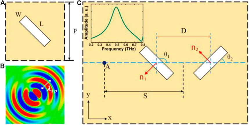
FIGURE 1. (A) The unit cell schematic of the proposed metasurface. The geometric parameters of the microslit were L = 200 μm, W = 50 μm, and p = 300 μm. (B) The simulated SP radiation pattern was excited by a narrow sub-wavelength microslit on the aluminum film under the incidence of a normal plane wave. (C) A schematic diagram of a pair of microslit resonators. They were used to derive the SP emission field at point A at a distance S from the center of the pair of microslits. D is the distance between the centers of the microslits.
The coupling of the microslit pair, as shown in Figure 1C, is excited by the plane wave and the electric field
where I represents the field amplitude of SP;
It can be easily obtained from Eq. (2) that the amplitude of the SP field at A is fixed, while the phase is freely controllable with a sign determined by the circular-polarization handedness and shift by the orientation angle. This shows that circular polarization can be used to switch the sign of the phase, thereby controlling the shape of the SP wavefront while maintaining the SP amplitude constant. In addition, a nearly arbitrary phase profile could be achieved even using a single straight column of microslit resonators because the phase shift enables the cover of whole
From the generalized Snell law, the SP coupling can be realized through constructing the phase of the microslits to satisfy
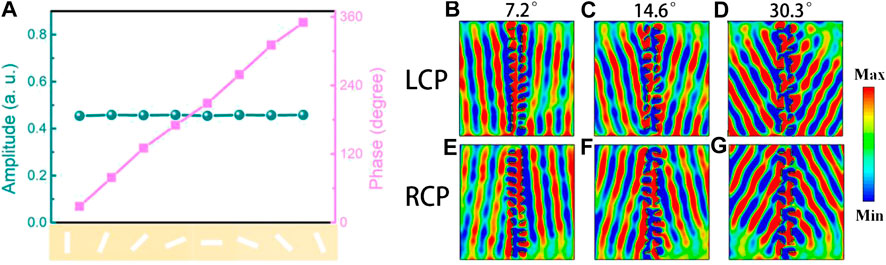
FIGURE 2. Simulated
To demonstrate the proposed scheme, we numerically demonstrated three types of metasurface with different phase gradients in the y direction. Figures 2B,E show different SP launches when the incident THz waves are LCP and RCP, respectively. The angle shift between two adjacent microslits is 22.5° in the y direction, which means that the metasurface can complete the shape of the wavefront within 8 unit cells. The anomalous angle of SP launch can be calculated easily as
The reason SP launching can be accurately and continuously manipulated is the proper relationship between adjacent microslit structures. And the distance D between the adjacent microslits played a vital role in achieving the launch of high efficiency SPs. The calculated field distributions at distance D of 200–400 μm, with a step of 50 μm, while keeping
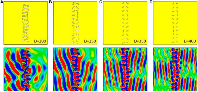
FIGURE 3. Calculated
To verify the controllability of launching SPs, a configuration was set up for generating a phase distribution by changing the orientation angle of each microslit (Figure 4). First, the microslits were distributed uniformly around a circle. Their orientation angles
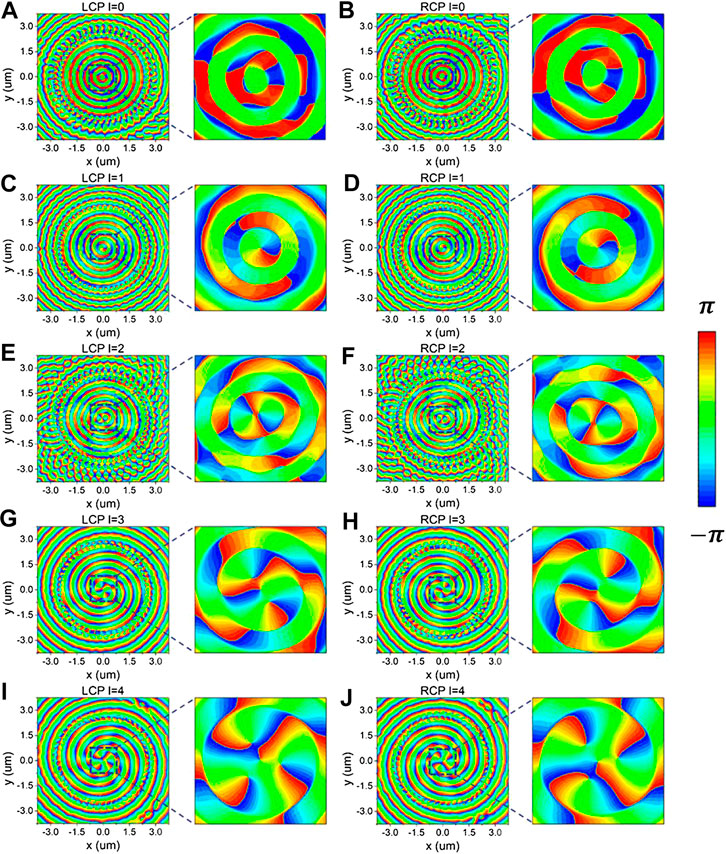
FIGURE 4. When the incident is LCP, the
Figures 4A,B show the phase distribution of the
Conclusion
In conclusion, anomalous launching and PV generators of SPs are theoretically demonstrated in a THz near-field metasurface platform by geometric phase. It should be noted that the diameter of the sub-wavelength metal microslit was less than
Experimental Section
Simulations were carried out by using the commercially available software package CST Microwave Studio. An open boundary condition was applied to the x and z directions to prevent reflections from the boundaries. For the deflector structure, a periodic boundary condition was used on the y direction with a 3,500 um × 3,500 um simulation area, but as the distance D changed, the simulation range changed accordingly; while for the OAM generator structure, an open boundary condition was applied to the y direction with a 6,500 um × 6,500 um simulation area. A normally incident circularly-polarized plane wave at 0.49 THz excited ZTSW on the substrate side and field distribution was observed from the air side.
Data Availability Statement
The original contributions presented in the study are included in the article/Supplementary Material, further inquiries can be directed to the corresponding authors.
Author Contributions
SW proposed the idea; PW, SH, CZ, and MH conducted pattern designs and numerical simulations; PW, SH, and YX fabricated the sample; PW performed the measurements; and SH and PW prepared the manuscript. XL and MX and MH supervised the overall projects. SW, PW, and SH analysed the data and discussed the results.
Conflict of Interest
The authors declare that the research was conducted in the absence of any commercial or financial relationships that could be construed as a potential conflict of interest.
References
1. Barnes WL, Dereux A, Ebbesen TW. Surface plasmon subwavelength optics. Nature. (2003) 424:824–30. doi:10.1038/nature01937
2. Nie S, Emory SR. Probing single molecules and single nanoparticles by surface-enhanced Raman scattering. Science. (1997) 275:1102–6. doi:10.1126/science.275.5303.1102
3. Oulton RF, Sorger VJ, Zentgraf T, Ma RM, Gladden C, Dai L, et al. Plasmon lasers at deep subwavelength scale. Nature. (2009) 461:629–32. doi:10.1038/nature08364
4. Berini P, Leon ID. Nat, Surface plasmon-polariton amplifiers and lasers. Nat Photon. (2011) 6:16–24. doi:10.1038/nphoton.2011.285
5. Ebbesen TW, Genet C, Bozhevolnyi SI. Surface-plasmon circuitry. Phys Today. (2008) 61:44. doi:10.1063/1.2930735
6. Sorger VJ, Oulton RF, Ma R, Zhang X. Toward integrated plasmonic circuits. MRS Bull. (2012) 37:728. doi:10.1557/mrs.2012.170
7. Liu J, Gao Y, Ran L, Guo K, Lu Z, Liu S. Focusing surface plasmon and constructing central symmetry of focal field with linearly polarized light. Appl Phys Lett. (2015) 106:013116. doi:10.1063/1.4905307
8. Xu Y, Zhang X, Tian Z, Gu J, Ouyang C, Li Y, et al. Mapping the near-field propagation of surface plasmons on terahertz metasurfaces. Appl Phys Lett. (2015) 107:021105. doi:10.1063/1.4926967
9. Xu Q, Zhang X, Xu Y, Ouyang C, Tian Z, GuJ , et al. Polarization-controlled surface plasmon holography. Laser Photon Rev. (2016) 11:1600212. doi:10.1002/lpor.201600212
10. Xu Q, Zhang X, Xu Y, Li Q, Li Y, Ouyang C, et al. Plasmonic metalens based on coupled resonators for focusing of surface plasmons. Sci Rep. (2016) 6:37861. doi:10.1038/srep37861
11. Yashunsky V, Lirtsman V, Zilbershtein A, Bein A, Schwartz B, Aroeti B, et al. Surface plasmon-based infrared spectroscopy for cell biosensing. J Biomed Opt. (2012) 17:081409. doi:10.1117/1.JBO.17.8.081409
12. Tan Q, Guo Q, Liu H, Huang X, Zhang S. Controlling the plasmonic orbital angular momentum by combining the geometric and dynamic phases. Nanoscale. (2017) 9:4944–4949. doi:10.1039/c7nr00124j
13. Gao Y, Gan Q, Xin Z, Cheng X, Bartoli FJ. Plasmonic mach-zehnder interferometer for ultrasensitive on-chip biosensing. ACS Nano. (2011) 5:9836–44. doi:10.1021/nn2034204
14. Liu Y, Palomba S, Park Y, Zentgraf T, Yin X, Zhang X. Compact magnetic antennas for directional excitation of surface plasmons. Nano Lett. (2012) 12:4853–8. doi:10.1021/nl302339z
15. Epstein I, Tsur Y, Arie A. Surface-plasmon wavefront and spectral shaping by near-field holography. Laser Photon Rev. (2016) 10:360. doi:10.1002/lpor.201500242
16. Yu N, Capasso F. Flat optics with designer metasurfaces. Nat Mater. (2014) 13:139. doi:10.1038/nmat3839
17. Chen HT, Taylor AJ, Yu N. A review of metasurfaces: physics and applications. Rep Prog Phys. (2016) 79:076401. doi:10.1088/0034-4885/79/7/076401
18. Smith DR, Pendry JB, Wiltshire MC. Metamaterials and negative refractive index. Science. (2004) 305:788–92. doi:10.1126/science.1096796
19. Shalaev VM. Optical negative-index metamaterials. Nat Photon. (2007) 1:41. doi:10.1364/META.2006.TuC3
20. Soukoulis CM, Wegener M. Past achievements and future challenges in the development of three-dimensional photonic metamaterials. Nat Photon. (2011) 5:523. doi:10.1038/nphoton.2011.154
21. Yu N, Genevet P, Kats MA, Aieta F, Tetienne JP, Capasso F, et al. Light propagation with phase discontinuities: generalized laws of reflection and refraction. Science. (2011) 334:333–7. doi:10.1126/science.1210713
22. Ni X, Emani NK, Kildishev AV, Boltasseva A, Shalaev VM. Broadband light bending with plasmonic nanoantennas. Science. (2012) 335:427. doi:10.1126/science.1214686
23. Zhang X, Tian Z, Yue W, Gu J, Zhang S, Han J, et al. Broadband terahertz wave deflection based on C-shape complex metamaterials with phase discontinuities. Adv Mater Weinheim. (2013) 25:4567–72. doi:10.1002/adma.201204850
24. Zhang X, Zhu Y, Mao C, Xu W, Ding H, Xie J, et al. Manipulating terahertz plasmonic vortex based on geometric and dynamic phase. Advanced Optical Materials. (2018) 1801328. doi:10.1002/adom.201801328
25. Liu L, Zhang X, Kenney M, Su X, Xu N, Ouyang C, et al. Broadband metasurfaces with simultaneous control of phase and amplitude. Adv Mater Weinheim. (2014) 26:5031–6. doi:10.1002/adma.201401484
26. Kim M, Wong AMH, Eleftheriades GV. Optical Huygens’ metasurfaces with independent control of the magnitude and phase of the local reflection coefficients. Phys. Rev. X. (2014) 4:041042. 10.1103/PhysRevX.4.041042
27. Yu N, Aieta F, Genevet P, Kats MA, Gaburro Z, Capasso F. A broadband, background-free quarter-wave plate based on plasmonic metasurfaces. Nano Lett. (2012) 12:6328–33. doi:10.1021/nl303445u
28. Cong L, Xu N, Han J, Zhang W, Singh R. A tunable dispersion-free terahertz metadevice with Pancharatnam-Berry-phase-enabled modulation and polarization control. Adv Mater Weinheim. (2015) 27:6630–6. doi:10.1002/adma.201502716
29. Cong L, Xu , Zhang W, Singh R. Polarization control in terahertz metasurfaces with the lowest order rotational symmetry. Adv. Opt. Mater. (2015) 3:1176. doi:10.1002/adom.201500100
30. Cong L, Srivastava YK, Singh R. Inter and intra-metamolecular interaction enabled broadband high-efficiency polarization control in metasurfaces. Appl Phys Lett. (2016) 108:011110. doi:10.1063/1.4939564
31. Wu PC, Tsai WY, Chen WT, Huang YW, Chen TY, Chen JW, et al. Versatile polarization generation with an aluminum plasmonic metasurface. Nano Lett. (2017) 17:445–452. doi:10.1021/acs.nanolett.6b04446
32 Sun S, He Q, Xiao S, Xu Q, Li X, Zhou L. Gradient-index meta-surfaces as a bridge linking propagating waves and surface waves. Nat Mater. (2012) 11:426–31. doi:10.1038/nmat3292
33. Lin J, Mueller JP, Wang Q, Yuan G, Antoniou N, Yuan XC, et al. Polarization-controlled tunable directional coupling of surface plasmon polaritons. Science. (2013) 340:331–4. doi:10.1126/science.1233746
34. Huang L, Chen X, Bai B, Tan Q, Jin G, Zentgraf T, et al. Helicity dependent directional surface plasmon polariton excitation using a metasurface with interfacial phase discontinuity. Light Sci. Appl. (2013) 2:e70. doi:10.1038/lsa.2013.26
35. Pors A, Nielsen MG, Bernardin T, Weeber J-C, Bozhevolnyi SI. Efficient unidirectional polarization-controlled excitation of surface plasmon polaritons. Light Sci Appl. (2014) 3:e197. doi:10.1038/lsa.2014.78
36. Spektor G, David A, Gjonaj B, Bartal G, Orenstein M. Metafocusing by a metaspiral plasmonic lens. Nano Lett. (2015) 15:5739–43. doi:10.1021/acs.nanolett.5b01571
37. Genevet P, Wintz D, Ambrosio A, She A, Blanchard R, Capasso F. Controlled steering of Cherenkov surface plasmon wakes with a one-dimensional metamaterial. Nat Nanotechnol. (2015) 10:804–9. doi:10.1038/nnano.2015.137
38. Xiao S, Zhong F, Liu H, Zhu S, Li J. Flexible coherent control of plasmonic spin-Hall effect. Nat Commun. (2015) 6:8360. doi:10.1038/ncomms9360
39. Tanemura T, Balram KC, Ly-Gagnon DS, Wahl P, White JS, Brongersma ML, Miller DA, et al. Multiple-wavelength focusing of surface plasmons with a nonperiodic nanoslit coupler. Nano Lett. (2011) 11:2693–8. doi:10.1021/nl200938h
40. Wintz D, Genevet P, Ambrosio A, Woolf A, Capasso F. Holographic metalens for switchable focusing of surface plasmons. Nano Lett. (2015) 15:3585–9. doi:10.1021/acs.nanolett.5b01076
41. Zhang X, Xu Q, Li Q, Xu Y, Gu J, Tian Z, et al. Asymmetric excitation of surface plasmons by dark mode coupling. Sci. Adv. (2016) 2:e1501142. doi:10.1126/sciadv.1501142
42. Allen L, Beijersbergen MW, Spreeuw RJ, Woerdman JP. Orbital angular momentum of light and the transformation of Laguerre-Gaussian laser modes. Phys. Rev. A. (1992) 45:8185–8189. doi:10.1103/physreva.45.8185
43. Jeon T, Grischkowsky D. THz Zenneck surface wave (THz surface plasmon) propagation on a metal sheet. Appl. Phys. Lett. (2006) 88:061113. doi:10.1063/1.2171488
44. Gong M, Jeon TI, Grischkowsky D. THz surface wave collapse on coated metal surfaces. Opt. Express. (2009) 17:17088–101. doi:10.1364/OE.17.017088
Keywords: surface plasmons, metasurfaces, geometric phases, plasmonic vortices, beam deflectors
Citation: Hu S, Wang P, Zhou C, Hu M, Xiong Y, Xu H, Li X, Xu M and Wang S (2021) Control of THz Surface Plasmons by Geometric Phases. Front. Phys. 8:612163. doi: 10.3389/fphy.2020.612163
Received: 30 September 2020; Accepted: 03 December 2020;
Published: 19 January 2021.
Edited by:
Yuancheng Fan, Northwestern Polytechnical University, ChinaReviewed by:
Xueqian Zhang, Tianjin University, ChinaOleg Rybin, V. N. Karazin Kharkiv National University, Ukraine
Copyright © 2021 Hu, Wang, Zhou, Hu, Xiong, Xu, Li, Xu and Wang. This is an open-access article distributed under the terms of the Creative Commons Attribution License (CC BY). The use, distribution or reproduction in other forums is permitted, provided the original author(s) and the copyright owner(s) are credited and that the original publication in this journal is cited, in accordance with accepted academic practice. No use, distribution or reproduction is permitted which does not comply with these terms.
*Correspondence: Mingyao Xu, MTk4ODAxOEB3dHUuZWR1LmNu; Shengxiang Wang, c2h4d2FuZ0B3dHUuZWR1LmNu