 Wei Li
 Li Wang
 Alex Henzen1
- 1Guangdong Provincial Key Laboratory of Optical Information Materials and Technology & Institute of Electronic Paper Displays, South China Academy of Advanced Optoelectronics, South China Normal University, Guangzhou, China
- 2School of Information Engineering, Zhongshan Polytechnic, Zhongshan, China
Electrowetting display (EWD) is a new reflective display technology, which has the advantages of ultra-low power consumption, high contrast, fast response and full-color. However, due to a hysteresis effect, accurate gray scale display of EWDs cannot be achieved, which seriously restricted the display effect and performance of EWDs. In order to reduce the influence of hysteresis effect, a multi waveform adaptive driving scheme was proposed in this paper. Firstly, a multi waveform driving system was designed and implemented by a STM32 master chip and an AD5304 driver chip. The driving system could automatically select different driving waveforms according to the preset switching conditions. Then, different driving waveforms were designed and implemented according to different driving stages of EWDs. Finally, driving waveforms were mapped with each stage of the driving process one by one to realize the adaptive driving of multiple waveforms. The experimental results showed that, compared with the conventional square wave, the maximum hysteresis difference of hysteresis curve could be reduced by 39.19% with the multi waveform driving scheme.
Introduction
As a new optical reflective display device, electrowetting displays (EWDs) have been greatly developed. EWDs have the advantages of ultra-low power consumption, high contrast, fast response and full-color [1]. The concept of EWDs was first proposed by G. Beni [2, 3]. The basic principle of EWDs is to manipulate the liquid transport in a microporous structure by electrowetting effect, so as to change the optical spatial coherence of porous surface and realize an optical display effect of white or transparent switching.
In 2003, a new reflective EWD principle based on oil-water two-phase dielectric wetting system was reported [4, 5]. In 2004, an EWD with high reflectivity was developed [6], which was four times as bright as a reflective liquid crystal display (LCD). At the same time, it also had the advantages of high contrast and fast video response. In 2005, a novel single-layer multi-color EWD which used a variety of dye pastes instead of the conventional color polarizer technology was proposed [7]. In 2010, a three-layer structure color EWD was fabricated by superimposing three primary colors [8]. In 2011, a scheme was proposed to realize a single-layer multi-color EWD by adding different colors of oil into sub-pixel by ink-jet printing (IJP) technology [9].
However, there are still many defects in EWDs, such as oil splitting, oil backflow, charge trapping, hysteresis effect, etc. [10, 11]. In order to solve these defects and further improve the optical performance of EWDs, many scholars have made a lot of efforts. An asymmetrical driving concept was proposed and a charge trapping suppression method was developed [12], but the variable electrode could lead to the instability of electric field force. And the hysteresis effect would be more significant. Then, a method was proposed to reduce oil splitting by adding a voltage rising gradient in the driving waveform [13], but the rising gradient could increase the response time of EWDs. In addition, an error diffusion algorithm based on pixel neighborhood gray information and direct current (DC) balanced driving waveform was proposed for suppressing the oil backflow [14]. However, the oil backflow caused by the charge trapping cannot be solved effectively. Recently, an amplitude-frequency mixed modulation driving system was proposed to improve the response speed for driving gray scales and enhance the oil stability [15], but the driving scheme was based on a single waveform, which limited the development of driving waveforms.
In order to reduce the influence of hysteresis effect and improve the display performance of EWDs. The reason of hysteresis effect was analyzed, and the hysteresis curve of EWDs was obtained by experiments. Then, a multi waveform adaptive driving system was designed and implemented, and it could effectively reduce the influence of hysteresis effect in EWDs.
Principles of Electrowetting Displays
Driving Principle of Electrowetting Displays
An EWD is mainly composed of glass substrate, indium tin oxides (ITO) guide electrode, hydrophobic insulation layer (HIL), pixel wall, colored oil, polar liquid, and top plate [16, 17], as shown in Figure 1A. Gray scale is realized in EWDs by applying an external voltage to control the movement of the colored oil [18]. The colored oil in a pixel spreads naturally and covers the whole pixel when no external voltage is applied, and the color of oil is displayed, as shown in Figure 1B. The colored oil is pushed to a corner in the pixel when the external voltage is applied, and the color of the substrate is displayed, as shown in Figure 1C. Figure 1D is the top view of oil spreading. Figure 1E is the top view of oil contracting.
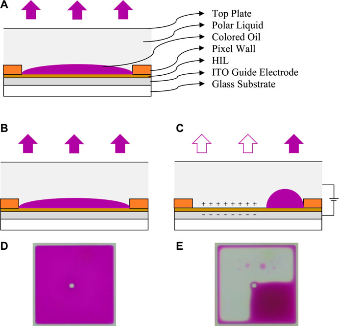
FIGURE 1. Principle of the EWD. (A) Pixel structure of the EWD. (B) Without an applied external voltage, the color of oil is displayed in a pixel (C) With an applied external voltage, the color of substrate is displayed. (D) The top view when the pixel is turned off. (E) The top view when the pixel is turned on.
The different degrees of oil contraction represent different optical states, which are characterized by the aperture ratio. The aperture ratio is a proportion of opening area in a whole pixel. The formula is defined as Eq. 1 [5].
In Eq. 1,
Principle of Hysteresis
The conventional sine wave is used to drive an EWD, as shown in Figure 2, the change of aperture ratio with driving voltage was tested. The results showed that the aperture ratio values of the same driving voltage value were different in the process of driving voltage rising and falling. This difference in optical response is called hysteresis effect [19].
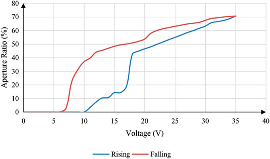
FIGURE 2. The change of aperture ratio in the process of voltage rising and falling when an EWD is driven by a sine driving waveform.
The hysteresis effect is caused by the contact angle hysteresis in the driving process. It is also the inconsistency between the advancing contact angle and the receding contact angle (oil contracting and spreading) of a droplet. As shown in Figure 3,
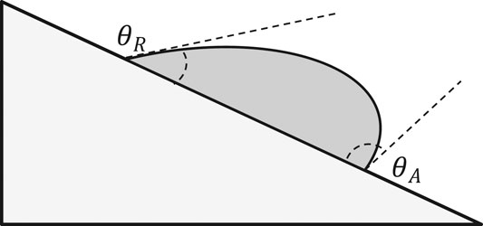
FIGURE 3. The inconsistency between the advancing contact angle and the receding contact angle.
It can be verified by Young's equation and Lippmann-Young equation [21]. Young's equation describes the relationship between the contact angle and the surface tension of droplets. As shown in Eq. 2,
The Lippmann-Young equation describes the relationship between the contact angle and the applied voltage in an electrowetting model. As shown in Eq. 3, where
The fundamental reason of contact angle hysteresis is the rough surface of hydrophobic insulation layer and the viscous resistance of two-phase liquid. And this process could be deduced and verified [22], the relationship between the contact angle and driving voltage in a driving process of EWDs can be described as Eq. 4, where,
The hysteresis effect seriously affects the gray scale display of EWDs, resulting in an inability of accurate gray scale. Without changing the structure and the surface material of hydrophobic insulating layer, the hysteresis effect can be reduced by driving methods. So, a multi-waveform driving system was designed and implemented, and different driving waveforms were designed for each driving stage.
Driving System Design for Multi Waveform
The driving system of EWDs has been reported in many papers. These driving systems were implemented with an FPGA (field programmable gate array) [23–25]. Although the performance was stable and the functions were rich, the multi waveform loading and conditional switching cannot be realized. In this paper, a multi waveform driving system was proposed, which could automatically select different waveforms according to preset conditions. The whole driving system was mainly composed of a hardware circuit board, a driving program and a waveform editor. The implementation of these three parts is shown as follows.
Hardware Circuit Board
The framework of hardware circuit board is shown in Figure 4A. The power module supplied power, and the control unit provided control logic for a whole circuit system, the main control chip was a STM32 (STM32F103RCT6). The control unit could communicate with a PC (personal computer) by a UART (universal asynchronous receiver transmitter) interface to receive command information and data information. In addition, it could communicate with digital-to-analog conversion (DAC) unit by a SPI (serial peripheral interface) interface to send waveform data and receive feedback information. At the same time, a SD-Card was attached to the control unit for the storage of waveform files. An AD5304 chip was used in the DAC unit, which was mainly used to convert the received digital signal of the control unit into analog signals. Finally, the analog signal was amplified to output an appropriate voltage for achieving the control purpose of EWDs. As shown in Figure 4B, it is a physical picture of the hardware circuit board.
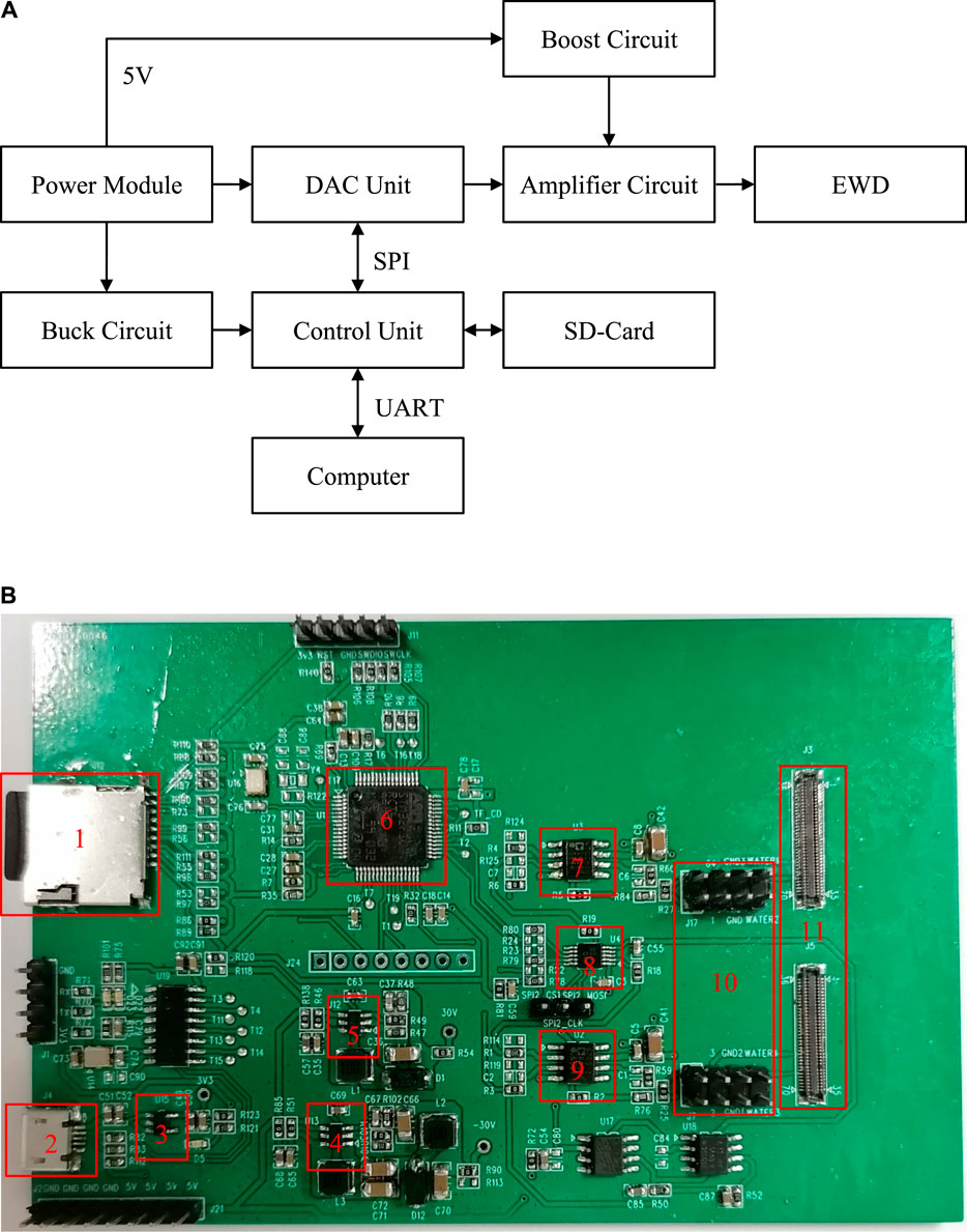
FIGURE 4. The hardware circuit board consists of a power module, a control unit, a DAC unit, a buck circuit, a boost circuit, an amplifier circuit, a SD-Card and communication interfaces. (A) The framework of the hardware circuit board. (B) The physical picture of the hardware circuit board. 1) SD-Card. 2) Power Module. 3) Buck Circuit. 4) Boost Circuit. 5) Boost Circuit. 6) Control Unit. 7) Amplifier Circuit. 8) DAC Unit. 9) Amplifier Circuit. 10) Interface A for EWDs. 11) Interface B for EWDs.
Driving Program
Driving program is the realization of control logics in a whole driving system. When the program is running, the initialization operation is performed first to reset each pin and communication interface. Then the system enters the command waiting interface. At this time, the control command can be entered. Users can control the system to load waveform files or set waveform switching conditions. Then, the driving program will analyze the waveform files when users give a driving instruction, and send the waveform data to drive EWDs according to switching conditions. In this paper, a STM32 (STM32F103RCT6) was adopted as the main control chip. The driving program was implemented on Windows 10 platform. The integrated development environment was Keil μVision5, and the development language was C programming language. The flow chart of the driving program is shown in Figure 5.
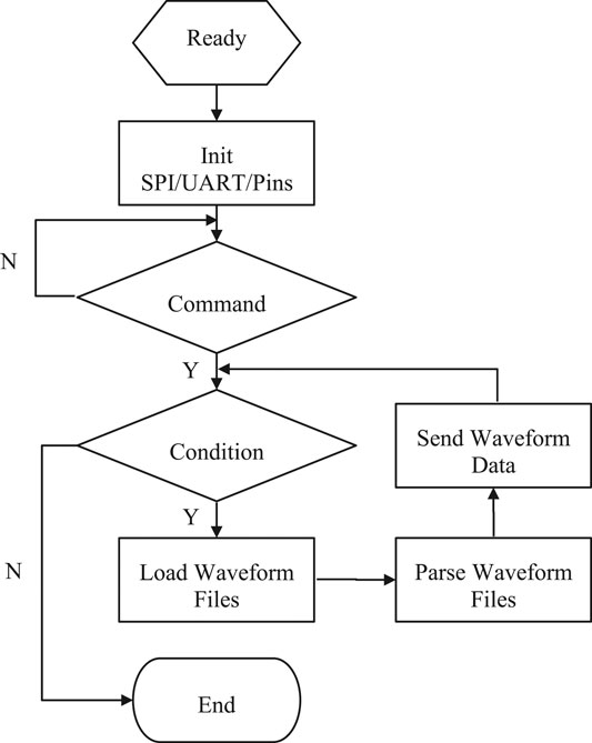
FIGURE 5. The flow chart of the driving program. When the program starts to run, the initialization operation is performed first. Then the system enters the command waiting interface. Finally, the corresponding operations are executed according to command types.
Waveform Editor
The waveform editor could implement the design of an arbitrary waveform and generate waveform data quickly. The generated waveform data can be saved in a hexadecimal format file, so that the backend hardware system can parse the file and output the corresponding waveform. The design interface of the waveform editor is shown in Figure 6. The waveform editor can edit seven waveforms at the same time. In the parameter setting area, the default voltage value of unedited driving waveforms channel can be set, and the waveform repeated interval and repeat times can also be set. In the generated hexadecimal format data, every 11 bytes were in a group. In order to reduce the file size, all channel values were compared in each data interval. If there were any changes, the group of data would be saved, otherwise the group of data could not be saved.
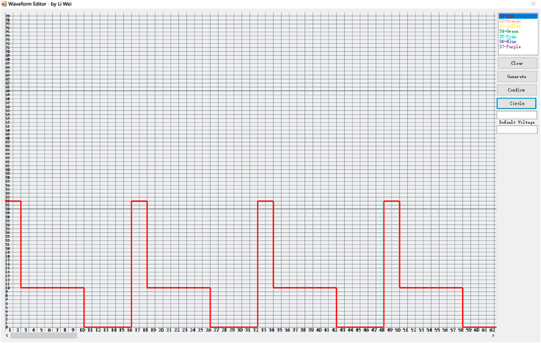
FIGURE 6. The screenshot of the waveform editor. The waveform editor could implement the design of an arbitrary waveform and generate waveform data quickly.
The proposed multi waveform driving system can achieve the purpose of multi waveform loading and condition switching. By using this driving system, the hysteresis effect of EWDs can be reduced. The workflow of the whole system is shown in Figure 7.
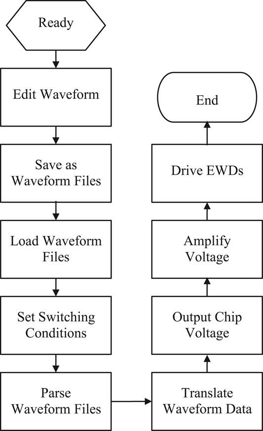
FIGURE 7. The workflow of the multi waveform driving system. It includes of waveform editing, waveform saving, waveform loading, conditions setting, waveform parsing, waveform translating and voltage amplifying.
Firstly, driving waveforms were designed by the waveform editor and saved as waveform files. By the reserved loading interface, the waveform files were loaded and parsed into waveform data. Then, switching conditions of the waveforms can be set. Switching conditions were the setting of voltage values. Finally, the corresponding waveform data was sent to the core driving chip by the driving program according to the current condition. So, EWDs can be driven to display contents by the interface of the hardware.
Driving Waveform Design for Reducing Hysteresis
For EWDs, if the pixel structure and oil material cannot be improved, the hysteresis effect cannot be completely eliminated. Moreover, due to the variability of driving processes, it is difficult to satisfy different driving processes with a same driving waveform. Therefore, it is necessary to design different driving waveforms for different driving processes. At the same time, the different driving waveforms can be switched automatically by the multi waveform driving system, so as to realize a better display effect. There are many ways to divide the driving process, and many kinds of multi waveform schemes can be designed.
First scheme, according to Eq. 4, the driving process of EWDs can be divided into advancing and receding processes. Between them, the advancing process can be divided into three stages, and the receding process can be divided into two stages. Then driving waveforms can be designed for these five stages. Finally, it is necessary to determine switching conditions of driving waveforms. The starting and ending voltage values of segmented waveforms in this scheme can be used as switching conditions.
Second scheme, the hysteresis curves of EWDs driven by square wave, sine wave and triangle wave are tested by experiments at first. Then three hysteresis curves are superimposed, and the better waveform segment can be used as the driving waveform of the corresponding stage, so as to form a multi waveform. Finally, it is necessary to determine the switching condition of waveform segments, the starting and ending voltage values of selected waveform segments can be set as switching conditions.
In this paper, the second scheme was used to design the multi waveform. As shown in Figure 8, the hysteresis curves of EWDs driven by a square wave, a sine wave and a triangle wave were measured by experiments. It can be seen from Figure 8 that under the same voltage, the square wave has the largest aperture ratio and the triangle wave has the smallest aperture ratio. This is because the overall power of the square wave is larger, so the electric field force is relatively larger. In order to reduce the hysteresis effect as much as possible, the following selections were made according to Figure 8. From 0 to 10 V, a square wave was selected as the first segment. From 10 to 18 V, a square wave was selected as the second segment. From 18 to 35 V, a sine wave was selected as the third segment. From 35 to 0 V, a triangle wave was selected as the fourth segment.
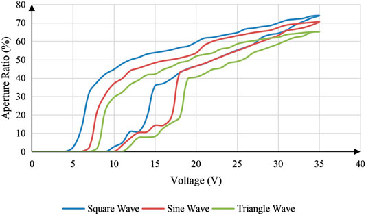
FIGURE 8. The hysteresis curves of EWDs driven by a square wave, a sine wave and a triangle wave.
Due to the influence of threshold voltages, the aperture ratio of the first segment was zero. But it could be activated by an activation voltage. Therefore, the first segment can be optimized as the driving waveform which is shown in Figure 9, EWDs were activated for 2ms with the maximum voltage in each waveform cycle. Finally, the multi waveform can be obtained, as shown in Figure 10.
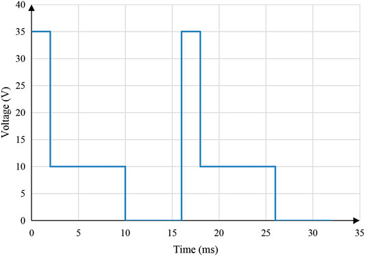
FIGURE 9. The driving waveform for the first segment of the multi waveform was optimized with an activation voltage. A waveform cycle includes a 2 ms activation phase, an 8 ms driving phase and a 6ms reset phase.
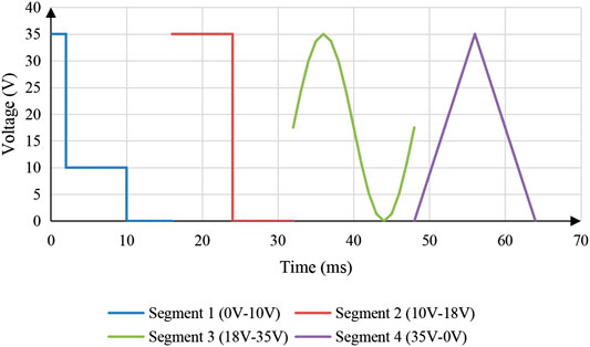
FIGURE 10. The multi waveform proposed in this paper. There were four segments in total. The first segment was from 0 to 10 V, which was a square wave optimized with an activation voltage. The second segment was from 10 to 18 V, which was a square wave. The third segment was from 18 to 35 V, which was a sine wave. The fourth segment was from 35 to 0 V, which was a triangle wave.
Experimental Results and Discussion
For the sake of evaluating the display performance of the proposed multi waveform driving scheme, an experimental platform was developed to measure the aperture ratio of EWDs, as shown in Figure 11. This experimental platform included a conventional driving system, a multi waveform driving system, a testing system, and an EWD panel. The conventional driving system was used to input the conventional driving waveform, which was consisted of a computer, a function generator, and a high-voltage amplifier. The multi waveform driving system was used to load the proposed multi waveform. The testing system was used to measure and record testing results, including a microscope, a high-speed camera, and a computer, and the EWD was the measured object. Its parameters are shown in Table 1. By this experimental platform, the conventional driving waveform and the adaptive multi waveform can be tested and compared.
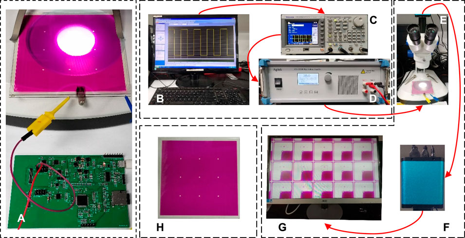
FIGURE 11. Experimental platform of the driving waveform for EWDs. (A) A multi waveform driving system. (B) A computer. (C) An arbitrary function generator ATA-2022H (Agitek, Xi’an, China). (D) An AFG-3052C (Agitek, Xi’an, China) high voltage amplifier. (E) A Microscope. (F) A high-speed camera. (G) A PC for measuring system. (H) An EWD panel.

TABLE 1. Parameters of an EWD panel.
First, the EWD was driven by the conventional driving system with conventional driving waveforms. Therefore, the hysteresis curves of the EWD driven by conventional driving waveforms could be tested. The experimental process can be divided into two steps. Firstly, the EWD was driven by the conventional driving system. The driving waveform was edited by a computer with ArbexPress software, and it was sent to a function generator by a serial communication, and then, the driving voltage of the driving waveform could be output when it was amplified by a high-voltage amplifier for driving an EWD. Secondly, the experimental data was measured by the testing system. The high-speed camera captured the display state by microscope in real time and transmitted testing data to a computer for calculating the aperture ratio. During the experiment, the temperature was kept a constant to avoid the influence of the external environment. The aperture ratio and driving voltage of the EWD with conventional driving waveforms were measured by the above-mentioned experimental platform. The measurement results are shown in Figure 12.
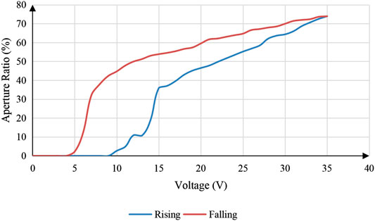
FIGURE 12. The hysteresis curve of an EWD driven by the square wave.
Second, the EWD was driven by the multi waveform driving system with the adaptive multi waveform. So, the hysteresis curve of EWDs driven by an adaptive multi waveform could be tested. Firstly, the multi waveforms were designed with the waveform editor and saved as the corresponding waveform files. Then, the multi waveform files were loaded by the reserved loading interface and switching conditions of the multi waveform were set. In the design process of multi waveforms, switching conditions of waveforms have been given. Finally, EWDs could be driven, and the aperture ratio data was tested and recorded by the testing system. The aperture ratio and driving voltage of the EWD with adaptive multi waveforms was measured. The measurement results are shown in Figure 13.
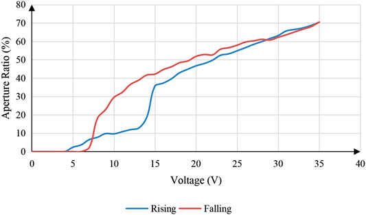
FIGURE 13. The hysteresis curve of an EWD driven by the multi waveform.
Compared with Figures 12, 13, it can be seen that the multi waveform driving system and adaptive multi waveform can effectively reduce the hysteresis effect of EWDs. The absolute value of the difference of aperture ratio in the process of driving voltage rising and falling with a same voltage value was defined as hysteresis difference. Then, a comparison of hysteresis difference with a square wave and a multi waveform could be obtained, as shown in Figure 14. Compared with the square wave, the maximum hysteresis difference of hysteresis curve could be reduced by 39.19% when the multi waveform driving scheme can be used.
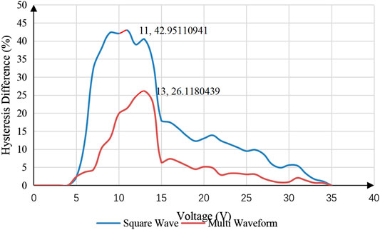
FIGURE 14. Comparison of the hysteresis difference of an EWD when it was driven by a square wave and a multi waveform.
Conclusions
In this paper, a multi waveform adaptive driving scheme was proposed. This driving scheme includes a driving system and a multi waveform. The driving system could automatically select different driving waveforms according to the preset conditions. The influence of the hysteresis effect of EWDs could be reduced by using the driving scheme. And the driving scheme could provide a strong guarantee for the realization of the accurate gray scale display in EWDs. Although the structural parameters (pixel size, pixel wall height, insulation layer thickness) of the EWD can affect the hysteresis curve, it cannot affect the result that the hysteresis difference of the adaptive multi waveform driving scheme is smaller than that of the conventional driving waveforms. So, the multi waveform adaptive driving scheme proposed in this paper provides a new idea for the design of driving waveforms.
Data Availability Statement
The raw data supporting the conclusions of this article will be made available by the authors, without undue reservation.
Author Contributions
WL and LW designed this project and carried out most of the experiments and data analysis. AH gave suggestions on the project management and conducted helpful discussion on the experimental results.
Funding
Supported by the National Key Research and Development Program of China (2016YFB0401502), Scientific research project of Guangdong Education Department (No. 2020ZDZX3083), Science and Technology Program of Guangzhou (No. 2019050001), Program for Chang Jiang Scholars and Innovative Research Teams in Universities (No. IRT_17R40), Program for Guangdong Innovative and Enterpreneurial Teams (No. 2019BT02C241), Science and technology project of Guangdong Province (No. 2018A050501013), Guangdong Provincial Key Laboratory of Optical Information Materials and Technology (No. 2017B030301007) and the 111 Project.
Conflict of Interest
The authors declare that the research was conducted in the absence of any commercial or financial relationships that could be constructed as a potential conflict of interest.
References
1. Yi Z, Huang Z, Lai S, He W, Wang L, Chi F, et al. Driving waveform design of electrowetting displays based on an exponential function for a stable grayscale and a short driving time. Micromachines (2020). 11(3):313. doi:10.3390/mi11030313.
2. Beni G,, Hackwood S. Electro-wetting displays. Appl Phys Lett (1981). 38(4):207–9. doi:10.1063/1.92322.
3. Beni G,, Tenan MA. Dynamics of electrowetting displays. J Appl Phys (1981). 52(10):6011–5. doi:10.1063/1.329822.
4. Hayes RA,, Feenstra BJ. Video-speed electronic paper based on electrowetting. Nature (2003). 425(6956):383–5. doi:10.1038/nature01988.
5. Roques-Carmes T, Hayes RA, Feenstra BJ, Schlangen LJ. Liquid behavior inside a reflective display pixel based on electrowetting. J Appl Phys (2004). 95(8):4389–96. doi:10.1063/1.1667595.
6. Roques-Carmes T, Hayes RA, Schlangen LJ. A physical model describing the electro-optic behavior of switchable optical elements based on electrowetting. J Appl Phys (2004). 96(11):6267–71. doi:10.1063/1.1810192.
7. Feenstra BJ. Rapid switching in multiple color active matrix driven electrowetting displays. IDW Symp Digest (2005). 2005:861–4.
8. You H,, Steckl AJ. Three-color electrowetting display device for electronic paper. Appl Phys Lett (2010). 97(2):023514. doi:10.1063/1.3464963.
9. Ku YS, Kuo SW, Huang YS, Chen CY, Lo KL, Cheng WY, et al. Single-layered multi-color electrowetting display by using ink-jet-printing technology and fluid-motion prediction with simulation. J Soc Inf Disp (2011). 19(7):488–95. doi:10.1889/JSID19.7.488.
10. Ku YS, Kuo SW, Tsai YH, Cheng PP, Chen JL, Lan KW, et al. The structure and manufacturing process of large area transparent electrowetting display. SID Symp Digest Techn Papers (2012). 43(1):850–2. doi:10.1002/j.2168-0159.2012.tb05919.x.
11. Sun B,, Heikenfeld J. Observation and optical implications of oil dewetting patterns in electrowetting displays. J Micromech Microeng (2008). 18(2):025027. doi:10.1088/0960-1317/18/2/025027.
12. Chen YC, Chiu YH, Lee WY, Liang CC. A charge trapping suppression method for quick response electrowetting displays. SID Symp Digest Tech Papers (2010). 41(1):842–5. doi:10.1889/1.3500607.
13. Zhang XM, Bai PF, Hayes RA, Shui LL, Jin ML, Tang B, et al. Novel driving methods for manipulating oil motion in electrofluidic display pixels. J Disp Technol (2016). 12(2):200–5. doi:10.1109/jdt.2015.2477947.
14. Lin S, Zeng S, Qian M, Lin Z, Guo T, Tang B. Improvement of display performance of electrowetting displays by optimized waveforms and error diffusion. J Soc Inf Disp (2019). 27(10):619–29. doi:10.1002/jsid.790.
15. Yi Z, Liu L, Wang L, Li W, Shui L, Zhou G. A driving system for fast and precise gray-scale response based on amplitude-frequency mixed modulation in TFT electrowetting displays. Micromachines (2019). 10(11):732. doi:10.3390/mi10110732.
16. Dou Y, Tang B, Groenewold J, Li F, Yue Q, Zhou R, et al. Oil motion control by an extra pinning structure in electro-fluidic display. Sensors (2018). 18(4):1114. doi:10.3390/s18041114.
17. Li W, Wang L, Zhang T, Lai S, Liu L, He W, et al. Driving waveform design with rising gradient and sawtooth wave of electrowetting displays for ultra-low power consumption. Micromachines (2020). 11(2):145. doi:10.3390/mi11020145.
18. Feenstra J. Video-speed electrowetting display technology. Handbook Visual Display Techn (2015). 1:1–13. doi:10.1007/978-3-642-35947-7_103-2.
19. Van Dijk R, Feenstra BJ, Hayes RA, Camps IGJ, Boom RGH, Wagemans MMH, et al. Gray scales for video applications on electrowetting displays. SID Symp Digest Tech Papers (2006). 37(1):1926–9. doi:10.1889/1.2433427.
20. Yi Z, Feng H, Zhou X, Shui L. Design of an open electrowetting on dielectric device based on printed circuit board by using a parafilm M. Front Phys (2020). 8:193. doi:10.3389/fphy. doi:10.3389/fphy.2020.00193.
21. Yi Z, Feng W, Wang L, Liu L, Lin Y, He W, et al. Aperture ratio improvement by optimizing the voltage slope and reverse pulse in the driving waveform for electrowetting displays. Micromachines (2019). 10(12):862. doi:10.3390/mi10120862.
22. Rui Z, Qi-Chao L, Ping W, Zhong-Cheng L. Contact angle hysteresis in electrowetting on dielectric. Chin Phys B (2015). 24(8):086801. doi:10.1088/1674-1056/24/8/086801.
23. Yi Z, Shui L, Wang L, Jin M, Hayes RA, Zhou G. A novel driver for active matrix electrowetting displays. Displays (2015). 37:86–93. doi:10.1016/j.displa.2014.09.004.
24. Chiu YH, Liang CC, Chen YC, Lee WY, Chen HY, Wu SH. Accurate-gray-level and quick-response driving methods for high-performance electrowetting displays. J Soc Inf Disp (2011). 19(11):741–8. doi:10.1889/JSID19.11.741.
Keywords: driving waveform, electrowetting display, hysteresis, driving scheme, multi waveform
Citation: Li W, Wang L and Henzen A (2020) A Multi Waveform Adaptive Driving Scheme for Reducing Hysteresis Effect of Electrowetting Displays. Front. Phys. 8:618811. doi: 10.3389/fphy.2020.618811
Received: 18 October 2020; Accepted: 11 November 2020;
Published: 03 December 2020.
Edited by:
Chongfu Zhang, University of Electronic Science and Technology of China, ChinaCopyright © 2020 Li, Wang and Henzen. This is an open-access article distributed under the terms of the Creative Commons Attribution License (CC BY). The use, distribution or reproduction in other forums is permitted, provided the original author(s) and the copyright owner(s) are credited and that the original publication in this journal is cited, in accordance with accepted academic practice. No use, distribution or reproduction is permitted which does not comply with these terms.
*Correspondence: Li Wang, d2FuZ2xpX29ldEAxNjMuY29t