 Zichuan Yi1*
 Hu Zhang1,2Wenjun Zeng1,3
 Haoqiang Feng3Zhengxing Long3
 Liming Liu1Yunfeng Hu1Xichen Zhou1
 Chongfu Zhang1,4
- 1School of Electronic Information, University of Electronic Science and Technology of China, Zhongshan Institute, Zhongshan, China
- 2School of Electronic Science and Engineering (National Exemplary School of Microelectronics), University of Electronic Science and Technology of China, Chengdu, China
- 3South China Academy of Advanced Optoelectronics, South China Normal University, Guangzhou, China
- 4School of Information and Communication Engineering, University of Electronic Science and Technology of China, Chengdu, China
Electrowetting display (EWD) is the most potential technology among new electronic paper technologies. It not only has the advantages of electrophoretic display (EPD) technology but also can realize color video playback. Therefore, this technology has been widely studied in recent years. Driving waveform is a voltage sequence which can drive pixels to display gray scales in EWDs. As one of the key technologies, it directly affects the display effect of pixels. In this paper, we give a review of the display principle of EWDs and the research status of driving waveforms. At the same time, the contact angle hysteresis, charge trapping, and oil splitting are also reviewed, which can provide a reference value for designing driving waveforms.
Introduction
Display is one of the most important modes of human-computer interactions, and display devices play a key role in daily life. Along with the rapid increase of network information, people expect better displays to meet various requirements. At present, the most common displays are liquid crystal displays (LCD) and light-emitting diode (LED) displays [1, 2]. These self-luminous displays have the defect of high power consumption which can severely limit the using time of electronic products. Nevertheless, electronic paper displays, such as electrophoretic displays (EPDs) and electrowetting displays (EWDs), have the advantages of paper-like reading experience and low power consumption due to its reflective display. EPDs are the most widely used electronic paper. It has been widely used in e-books, e-labels, etc. However, it cannot achieve video playback and the luminance of color is not enough [3–6]. As a result, many scholars began to pay attention to EWDs for obtaining better paper-like display performance in recent years.
The principle of EWDs was first proposed by Beni in 1981 [7]. In 2003, Hayes and Feenstra have successfully demonstrated that the electrowetting technology can be used to form a basis of a new reflective display. Its display principle is to utilize the voltage-controlled movement of a colored oil [8]. As a new reflective electronic paper display, EWDs have excellent display characteristics, such as paper-like reading experience [9, 10]; low power consumption [11, 12]; color display [13–16]; fast response speed which can meet the requirements of video playback [17]; low manufacturing cost because part of the manufacturing process is the same as LCDs [18, 19]. Hence, EWD technology becomes the most potential paper-like display technology. The voltage sequence which can control gray scales in EWDs is driving waveform [20–23]. The earliest driving waveform of EWDs is a pulse width modulated (PWM) square wave [24]. However, some defects are caused by this driving waveform, such as gray scale distortion which is caused by contact angle hysteresis [25–28]; maximum aperture ratio is reduced due to oil splitting [29–31]; oil backflow caused by charge trapping in the hydrophobic insulator [32–36]. The movement of oil is directly controlled by the driving waveform, the optimization of driving waveform can affect the display effect of EWDs. Hence, the equivalent circuit models, capacitor-voltage (C-V) characteristics and contact angle hysteresis characteristic of EWDs have been studied by scholars, and some new driving waveforms were proposed for better performance of EWDs.
In this paper, driving waveforms of EWDs are summarized, and classified with different categories according to functions. It includes optimizing contact angle hysteresis, reducing charge trapping and oil splitting. The display quality of EWDs was greatly improved by these driving waveforms. Furthermore, it provided an important reference for the further study of EWDs.
Principle
Principle of Electrowetting Displays
EWD is essentially an optical switch [37, 38]. Its structure is shown in Figure 1A. Each pixel is composed of a hydrophobic insulating layer, colored oil, polar liquid, pixel walls, a electrode which is made by ITO (Indium tin oxide) glass, a substrate. The colored oil is controlled by driving voltage to turn pixels on or off. The state of oil shrinkage can be described by the contact angle. The Lippmann-Young equation is considered as the basic theory of electrowetting technology. As shown in Eq. 1 [39–42]. The relationship between the voltage and the contact angle can be described by this equation.
Where
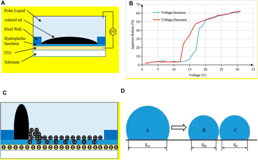
FIGURE 1. The structure of an EWD pixel and the phenomenon of defects in EWDs. (A) The whole pixel is covered with oil and the color of oil is displayed when the driving voltage is 0 V. (B) Phenomenon of contact angle hysteresis. The blue curve is the aperture ratio when the driving voltage is increased from 0 to 30 V, and the red curve is the aperture ratio when the driving voltage is decreased from 30 to 0 V. (C) Phenomenon of charge trapping. When the oil shrinks to one corner of a pixel, the charge distribution in a pixel. Charge trapping would be caused when the interaction between ions and hydrophobic insulating layer is stronger than that between ions and conductive liquid. (D) Phenomenon of oil splitting.
When the driving voltage is 0 V, the contact angle is approximately equal to zero due to Lippmann-Young equation. At this stage, because the oil is spread on the substrate, the pixel displays the color of colored oil, as shown in Figure 1A. With the increase of driving voltage, the electric field force is increased. Therefore, the oil original force balance is broken and oil begins to shrink to one corner of a pixel. The oil completely shrinks in one corner of the pixel when the voltage increases to
Contact Angle Hysteresis
Ideally, in the process of driving voltage rise or fall, the aperture ratio of the same driving voltage value should be the same. But experimental result is completely inconsistent with the expectation. The relationship between aperture ratio and voltage when the driving voltage rises from 0 to 30 V and falls from 30 to 0 V can be tested, respectively. As shown in Figure 1B [48]. The blue curve represents the relationship between the aperture ratio and the voltage when the driving voltage is rising. The red curve represents the relationship between the aperture ratio and the voltage when the driving voltage is falling. When the driving voltage is close to 0 and 30 V, the aperture ratio of these two curves almost coincide. But the difference of the aperture ratio is big when the driving voltage is in the middle stage. When the aperture ratio increases as the voltage increases, the contact angle is called as advancing angle. On the contrary, when the aperture ratio decreases as the voltage decreases, the contact angle is called as receding angle. Therefore, this distortion is called contact angle hysteresis [48]. The accurate gray scale display cannot be achieved because of this phenomenon.
Charge Trapping
Theoretically, the aperture ratio of a pixel is related to the applied voltage due to Lippmann-Young equation. But the oil can backflow when the same voltage is applied continuously. Thus, the aperture ratio is reduced. It has been found that some charge is trapped in the hydrophobic insulator when driving voltage is applied to EWDs [49]. The charge distribution is shown in Figure 1C. A three-phase contact line is formed where the oil, water and hydrophobic insulator are in contact. Positive ions gather on the three-phase contact line, and then, the nearby electric field can be distorted. The backflow can be caused due to the imbalance between Laplace pressure and Maxwell pressure at the three-phase contact line [50]. It can also reduce the maximum aperture ratio of EWDs.
Oil Splitting
Ideally, the oil shrinks in one corner of a pixel when driving voltage is applied to EWD in the process of oil shrinkage. However, oil may be split to two or more parts. The reason is that the charges in the hydrophobic insulator can cause a sudden change in electric field. When the capacitance value of a pixel increases rapidly, it is likely to cause oil splitting [51]. As shown in Figure 1D, the oil is divided into
Driving Waveforms Design
Driving Waveforms for Optimizing Contact Angle Hysteresis
The fundamental reason of contact angle hysteresis is the rough surface of hydrophobic insulation layer and the viscous resistance of two-phase liquid [52]. The precise gray scale cannot be displayed by EWDs because of contact angle hysteresis. The contact angle hysteresis can be reduced by optimizing driving waveforms. A multi-waveform adaptive driving scheme was proposed [53]. In this scheme, the contact angle hysteresis curves of EWDs driven by a square wave, a sine wave and a triangle wave were tested. Then, the optimal waveform of each stage could be selected by superimposing the three hysteresis curves, and an activation voltage sequence was added in front of the first stage. The maximum distortion caused by contact angle hysteresis could be effectively reduced by this driving scheme. Besides, the inhibitory effect of alternating current (AC) voltage on contact angle hysteresis was proved in another driving scheme [48].
Driving Waveforms for Reducing Charge Trapping and Oil Backflow
With an applied constant voltage, the shrinking oil cannot be maintained in a stable state because of charge trapping. This defect can also be solved by optimizing driving waveforms. A method showed that charge trapping can be reduced by a reverse electrode pulse voltage which takes a few milliseconds, and the proposed driving waveform is shown in Figure 2A [54]. Furthermore, the influence of oil backflow caused by charge trapping can also be reduced by the reset signal [55], as shown in Figure 2B. The proposed driving waveform was divided into a driving signal and a reset signal. The driving signal
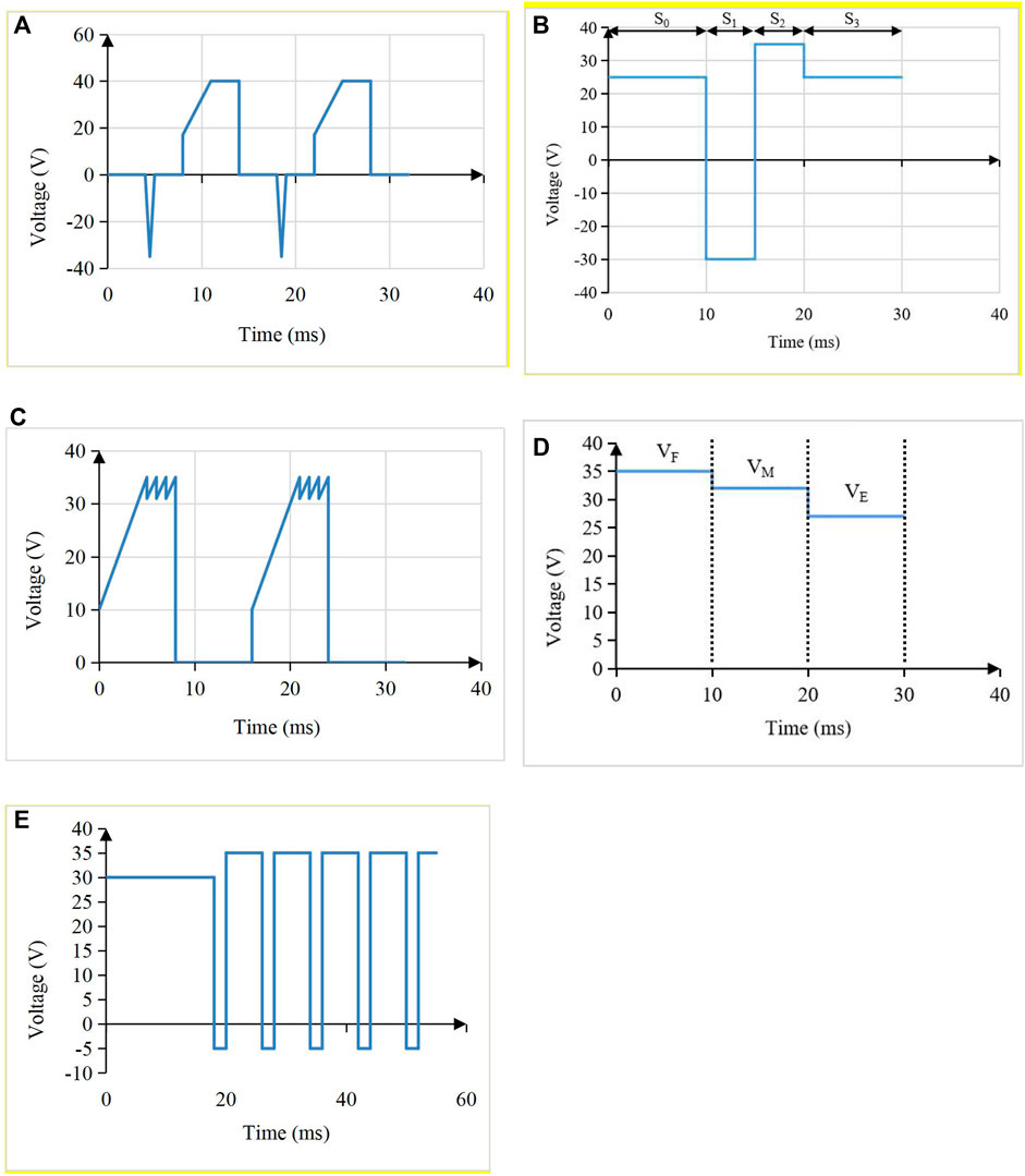
FIGURE 2. Different driving waveforms. (A) The multi structural driving waveform was designed to increase aperture ratio. (B) Driving waveform with a rising gradient and a sawtooth wave was designed to reduce power consumption. (C) The driving waveform with a reset signal. The reset signal consisted of
Driving Waveforms for Reducing Response Time
In order to obtain a higher frame rate video playback and a better display effect, it is necessary to shorten the response time of EWDs. There are several different methods to achieve this goal. First, although some defects are caused by contact angle hysteresis, the hysteresis curve can help to design new waveforms. An amplitude-frequency mixed modulation driving system was proposed according to the contact angle hysteresis, as shown in Figure 2D [60]. The driving voltage and driving time of each stage were determined by the hysteresis curve of a target gray scale. Next, a driving waveform based on an exponential function was proposed to reduce the response time [51]. The optimal time constant of the exponential function was designed by testing the influence of the time constant on the aperture ratio oscillation range. Then, it has been proved that excessive reverse voltage can cause a chemical reaction between water and ITO [50]. In order to solve this problem, a mixed DC and AC waveform was proposed, as shown in Figure 2E. The driving waveform was composed of two parts. The first part was a DC driving stage. It was used to drive pixels to reach target aperture ratios. The second part was an AC driving stage, and a reverse voltage was used to prevent oil backflow. This scheme could effectively reduce the response time. Lastly, due to the response speed of the oil was increased when the driving voltage was increased, the work showed that overdriving voltage can reduce the response time [61]. The influence of different overdriving voltages on response time was tested in this work.
Driving Waveforms for Reducing Oil Splitting
The reset frame is often used to solve the problem of charge trapping in EWDs. However, the reset frame could affect the instantaneous display state, such as flickers and the decrease of reflective luminance [57]. Therefore, a separated reset waveform was proposed to solve this problems [62]. The instantaneous reverse driving voltage can be achieved by adjusting the voltage of the common electrode. The charges can be released quickly with the overdriving voltage, and another lower instantaneous reverse driving can keep the oil active. In addition, DC balance is not complied in the improved multi-gray scales dynamic symmetrical driving scheme, which may cause polarization in EWDs. Therefore, a DC balanced driving waveform was proposed [63]. In this work, a long frame was divided into two short frames. In the two short frames, DC balance can be complied due to the reversal of polarity.
Generally, the oil splitting caused by the sudden change of electric field force could be prevented by a rising voltage. In a previous study, the sinusoidal waveform could reduce oil splitting effectively [64]. Therefore, a novel driving scheme was proposed to reduce oil splitting [65]. The driving voltage increased gradually from a value which was below the threshold voltage to a final voltage with a sinusoidal curve. It was proved that this driving waveform could reduce oil splitting and increase the aperture ratio of pixels.
Conclusion
The design of driving waveform plays a key role for improving the display quality of EWDs. In this paper, we reviewed new driving waveforms. At first, the shortcomings of EWDs were described, including contact angle hysteresis, charge trapping phenomenon and oil splitting. Then, driving waveforms for improving these shortcomings were classified. It provide a reference value for reducing response time, increasing aperture ratio and improving oil stability of EWDs. In the future, driving waveforms design would become an important part of driving system design with the development of EWDs, and an excellent driving waveform design is expected to achieve higher quality performance for EWDs.
Author Contributions
ZY and HZ discussed and wrote the manuscript together. WZ, HF, ZL, LL, and YH discussed and corrected the manuscript. XZ and CZ also helped with drawing the figures. All authors have read and agreed to the published version of the manuscript.
Funding
This research was funded by the Guangdong Basic and Applied Basic Research Foundation (No. 2020A1515010420), Construction project of professional quality engineering in 2020 (No. YLZY202001), the Key Research Platforms and Research Projects in Universities and Colleges of Guangdong Provincial Department of Education (No. 2018KQNCX334), the Zhongshan Innovative Research Team Program (No. 180809162197886), Guangdong Provincial Key Laboratory of Optical Information Materials and Technology (No. 2017B030301007), the Project for Innovation Team of Guangdong University (No. 2018KCXTD033), and the National Key R&D Program of China (No. 2018YFB0407100-02).
Conflict of Interest
The authors declare that the research was conducted in the absence of any commercial or financial relationships that could be construed as a potential conflict of interest.
References
1. Lee S-M, Kwon JH, Kwon S, Choi KC. A Review of flexible OLEDs toward highly durable unusual displays. IEEE Trans Electron Devices (2017) 64(5):1922–31. doi:10.1109/TED.2017.2647964
2. Han J-W, Hwang M-C, Kim S-G, You T-H, Ko S-J. Vector quantizer based block truncation coding for color image compression in LCD overdrive. IEEE Trans Consumer Electron (2008) 54(4):1839–45. doi:10.1109/TCE.2008.4711243
3. Jin M, Shen S, Yi Z, Zhou G, Shui L. Optofluid-based Reflective displays. Micromachines (2018) 9(4):159. doi:10.3390/mi9040159
4. Bai PF, Hayes RA, Jin M, Shui L, Yi ZC, Wang L, et al. REVIEW OF PAPER-LIKE DISPLAY TECHNOLOGIES (Invited Review). Pier (2014) 147:95–116. doi:10.2528/PIER13120405
5. Kao W-C, Tsai J-C. Driving method of three-particle electrophoretic displays. IEEE Trans Electron Devices (2018) 65(3):1023–8. doi:10.1109/TED.2018.2791541
6. Yi Z, Zeng W, Ma S, Feng H, Zeng W, Shen S, et al. Design of driving waveform based on a damping oscillation for optimizing Red saturation in three-color electrophoretic displays. Micromachines (2021) 12(2):162. doi:10.3390/mi12020162
7. Beni G, Hackwood S. Electro‐wetting displays. Appl Phys Lett (1981) 38(4):207–9. doi:10.1063/1.92322
8. Hayes RA, Feenstra BJ. Video-speed electronic paper based on electrowetting. Nature (2003) 425(6956):383–5. doi:10.1038/nature01988
9. Heikenfeld J, Drzaic P, Yeo J-S, Koch T. Review Paper: A critical Review of the present and future prospects for electronic paper. J Soc Inf Display (2011) 19(2):129–56. doi:10.1889/JSID19.2.129
10. Giraldo A, Aubert J, Bergeron N, Li F, Slack A, van de Weijer M. 34.2: Transmissive Electrowetting-Based Displays for Portable Multi-Media Devices. SID Symp Dig (2009) 40(1):479–82. doi:10.1889/1.3256820
11. Dou Y, Wang B, Jin M, Yu Y, Zhou G, Shui L. A Review on self-assembly in microfluidic devices. J Micromech Microeng (2017) 27(11):113002. doi:10.1088/1361-6439/aa84db
12. Chen Z, Lin S, Lin Z, Liao Q, Li T, Tang B. Design of Video Display Driving System for Low-power Electrowetting Display. Acta Photonica Sinica (2020) 49(2):222002. doi:10.3788/gzxb20204902.0222002
13. Heikenfeld J, Zhou K, Kreit E, Raj B, Yang S, Sun B, et al. Electrofluidic displays using Young-Laplace transposition of brilliant pigment dispersions. Nat Photon (2009) 3(5):292–6. doi:10.1038/nphoton.2009.68
14. You H, Steckl AJ. Three-color electrowetting display device for electronic paper. Appl Phys Lett (2010) 97(2):023514:doi:10.1063/1.3464963
15. Hayes RA, Feenstra BJ, Camps IGJ, Hage LM, Roques-Carmes T, Schlangen LJM, et al. 52.1: A high brightness colour 160 PPI Reflective display technology based on electrowetting. SID Symp Dig (2004) 35(1):1412–5. doi:10.1889/1.1825770
16. Massard R, Mans J, Adityaputra A, Leguijt R, Staats C, Giraldo A. Colored oil for electrowetting displays. J Inf Display (2013) 14(1):1–6. doi:10.1080/15980316.2012.751939
17. Mingyong Q, Shanling L, Suyun Z, Zhixian L, Tailiang G, Biao T. Real-time dynamic driving system implementation of electrowetting display. Opto-Electronic Eng (2019) 46(06):180623. doi:10.12086/oee.2019.180623
18. Zhao R, Cumby B, Russell A, Heikenfeld J. Large area and low power dielectrowetting optical shutter with local deterministic fluid film breakup. Appl Phys Lett (2013) 103(22):223510. doi:10.1063/1.4834095
19. Tröls A, Enser H, Jakoby B. Modeling and fabrication of low-cost electrowetting actuators for flexible microfluidic display applications. IEEE SENSORS (2016) 1–3. doi:10.1109/ICSENS.2016.7808429
20. Roques-Carmes T, Hayes RA, Feenstra BJ, Schlangen LJM. Liquid behavior inside a Reflective display pixel based on electrowetting. J Appl Phys (2004) 95(8):4389–96. doi:10.1063/1.1667595
21. Zhou M, Zhao Q, Tang B, Groenewold J, Hayes RA, Zhou G. Simplified dynamical model for optical Response of electrofluidic displays. Displays (2017) 49:26–34. doi:10.1016/j.displa.2017.05.003
22. Tang B, Groenewold J, Zhou M, Hayes RA, Zhou G. Interfacial electrofluidics in confined systems. Sci Rep (2016) 6:26593. doi:10.1038/srep26593
23. Feng H, Yi Z, Sun Z, Zeng W, Wang L, Yang J, et al. A spliceable driving system design for digital microflfluidics platform based on indium tin oxide substrate. J Nanoelectronics Optoelectronics (2020) 15(9):1127–36. doi:10.1166/jno.2020.2838
24. Yi Z, Shui L, Wang L, Jin M, Hayes RA, Zhou G. A novel driver for active matrix electrowetting displays. Displays (2015) 37:86–93. doi:10.1016/j.displa.2014.09.004
25. Xu ZN. An algorithm for selecting the most accurate protocol for contact angle measurement by drop shape analysis. Rev Scientific Instr (2014) 85(12):125107. doi:10.1063/1.4903198
26. Li F, Mugele F. How to make sticky surfaces slippery: Contact angle hysteresis in electrowetting with alternating voltage. Appl Phys Lett (2008) 92(24):244108. doi:10.1063/1.2945803
27. Gao J, Mendel N, Dey R, Baratian D, Mugele F. Contact angle hysteresis and oil film lubrication in electrowetting with two immiscible liquids. Appl Phys Lett (2018) 112(20):203703. doi:10.1063/1.5034510
28. Kulinich SA, Farzaneh M. Effect of contact angle hysteresis on water droplet evaporation from super-hydrophobic surfaces. Appl Surf Sci (2009) 255(7):4056–60. doi:10.1016/j.apsusc.2008.10.109
29. Andrea G, Paul V, Daniel F, Marco S, Jasper A, Mathieu W, et al. 46.3: Improved oil motion control and hysteresis‐free pixel switching of electrowetting displays. SID Symp Dig Tech Pap (2012) 43(1):625–8. doi:10.1002/j.2168-0159.2012.tb05859.x
30. Bansal S, Sen P. Effect of electrowetting induced capillary oscillations on coalescence of compound droplets. J Colloid Interf Sci (2018) 530:223–32. doi:10.1016/j.jcis.2018.05.090
31. Zhao Q, Tang B, Dong B, Li H, Zhou R, Guo Y, et al. Electrowetting on dielectric: experimental and model study of oil conductivity on Rupture voltage. J Phys D: Appl Phys (2018) 51(19):195102. doi:10.1088/1361-6463/aabb69
32. Lu Y, Sur A, Pascente C, Ravi Annapragada S, Ruchhoeft P, Liu D. Dynamics of droplet motion induced by Electrowetting. Int J Heat Mass Transfer (2017) 106:920–31. doi:10.1115/HT2016-733110.1016/j.ijheatmasstransfer.2016.10.040
33. Ounnunkad K, Patten HV, Velický M, Farquhar AK, Brooksby PA, Downard AJ, et al. Electrowetting on conductors: anatomy of the phenomenon. Faraday Discuss (2017) 199:49–61. doi:10.1039/c6fd00252h
34. Buehrle J, Herminghaus S, Mugele F. Interface profiles near three-phase contact lines in electric fields. Phys Rev Lett (2003) 91(8):086101. doi:10.1103/PhysRevLett.91.086101
35. Li X, Tian H, Shao J, Ding Y, Chen X, Wang L, et al. Decreasing the saturated contact angle in electrowetting-on-dielectrics by controlling the charge trapping at liquid-solid interfaces. Adv Funct Mater (2016) 26(18):2994–3002. doi:10.1002/adfm.201504705
36. Kilaru MK, Heikenfeld J, Lin G, Mark JE. Strong charge trapping and bistable electrowetting on nanocomposite fluoropolymer:BaTiO3 dielectrics. Appl Phys Lett (2007) 90(21):212906. doi:10.1063/1.2743388
37. Roques‐Carmes T, Hayes R, Schlangen L. A physical model describing the electro‐optic behavior of switchable optical elements based on electrowetting. J Appl Phys (2004) 96(11):6267–71. doi:10.1063/1.1810192
38. Duan MZ, Hayes RA, Zhang X, Zhou GF. A Reflective display technology based on electrofluidics. Amm (2014) 670-671:976–81. doi:10.4028/www.scientific.net/AMM.670-671.976
39. Seveno D, Blake TD, De Coninck J. Young's equation at the nanoscale. Phys Rev Lett (2013) 111(9):096101. doi:10.1103/PhysRevLett.111.096101
40. Navascues G. Liquid surfaces: theory of surface tension. Rep Prog Phys (2001) 42(7):1131–86. doi:10.1088/0034-4885/42/7/002
41. Moon H, Cho SK, Garrell RL, Kim C-JC. Low voltage electrowetting-on-dielectric. J Appl Phys (2002) 92(7):4080–7. doi:10.1063/1.1504171
42. Feng H, Yi Z, Yang R, Qin X, Shen S, Zeng W, et al. Designing Splicing Digital Microfluidics Chips Based on Polytetrafluoroethylene Membrane. Micromachines (2020) 11(12):1067. doi:10.3390/mi11121067
43. Luo Z, Luo J, Zhao W, Cao Y, Lin W, Zhou G. A high-Resolution and intelligent dead pixel detection scheme for an electrowetting display screen. Opt Rev (2018) 25(1):18–26. doi:10.1007/s10043-017-0382-3
44. Zhou K, Heikenfeld J, Dean KA, Howard EM, Johnson MR. A full description of a simple and scalable fabrication process for electrowetting displays. J Micromech Microeng (2009) 19(6):065029. doi:10.1088/0960-1317/19/6/065029
45. Sun B, Zhou K, Lao Y, Heikenfeld J, Cheng W. Scalable fabrication of electrowetting displays with self-assembled oil dosing. Appl Phys Lett (2007) 91(1):011106. doi:10.1063/1.2753697
46. Wu H, Tang B, Hayes R, Dou Y, Guo Y, Jiang H, et al. Coating and patterning functional materials for large area electrofluidic arrays. Materials (2016) 9(8):707. doi:10.3390/ma9080707
47. Yi Z, Zeng W, Ma C, Feng H, Yang J, Liu L, et al. A Real‐time touch control system design based on field‐programmable gate array via optimizing Bresenham algorithm for electrowetting displays. J Soc Inf Display (2021) 29:573–83. doi:10.1002/jsid.1001
48. Wang L, Zhang H, Li W, Li J, Yi Z, Wan Q, et al. Driving scheme optimization for electrowetting displays based on contact angle hysteresis to achieve precise gray-scales. Front Phys (2021) 9:655547. doi:10.3389/fphy.2021.655547
49. Wu H, Dey R, Siretanu I, Ende D, Shui L, Zhou G, et al. Electrically controlled localized charge trapping at amorphous fluoropolymer-electrolyte interfaces. Small (2019) 16(2):1905726. doi:10.1002/smll.201905726
50. Liu L, Wu Z, Wang L, Zhang T, Li W, Lai S, et al. Design of an AC driving waveform based on characteristics of electrowetting stability for electrowetting displays. Front Phys (2020) 8:618752. doi:10.3389/fphy.2020.618752
51. Yi Z, Huang Z, Lai S, He W, Wang L, Chi F, et al. Driving Waveform Design of Electrowetting Displays Based on an Exponential Function for a Stable Grayscale and a Short Driving Time. Micromachines (2020) 11(3):313. doi:10.3390/mi11030313
52. Zhao R, Liu Q-C, Wang P, Liang Z-C. Contact Angle Hysteresis in Electrowetting on Dielectric. Chin Phys. B (2015) 24(8):086801–496. doi:10.1088/1674-1056/24/8/086801
53. Li W, Wang L, Henzen A. A Multi Waveform Adaptive Driving Scheme for Reducing Hysteresis Effect of Electrowetting Displays. Front Phys (2020) 8:618811. doi:10.3389/fphy.2020.618811
54. Yi Z, Feng W, Wang L, Liu L, Lin Y, He W, et al. Aperture Ratio improvement by optimizing the voltage slope and Reverse pulse in the driving waveform for electrowetting displays. Micromachines (2019) 10(12):862. doi:10.3390/m110120862
55. Zhang T, Deng Y. Driving Waveform Design of Electrowetting Displays Based on a Reset Signal for Suppressing Charge Trapping Effect. Front Phys (2021) 9:672541. doi:10.3389/fphy.2021.672541
56. Luo ZJ, Zhang WN, Liu LW, Xie S, Zhou G. Portable multi-gray scale video playing scheme for high-performance electrowetting displays. Jnl Soc Info Display (2016) 24(6):345–54. doi:10.1002/jsid.444
57. Li W, Wang L, Zhang T, Lai S, Liu L, He W, et al. Driving waveform design with Rising gradient and sawtooth wave of electrowetting displays for ultra-low power consumption. Micromachines (2020) 11(2):145. doi:10.3390/mi11020145
58. Van Dijk R, Feenstra BJ, Hayes RA, Camps IGJ, Boom RGH, Wagemans MMH, et al. 68.3: Gray Scales for Video Applications on Electrowetting Displays. SID Symp Dig (2006) 37(1):1926–9. doi:10.1889/1.2433427
59. Qian M, Lin S, Zeng S, Lin Z, Guo T, Tang B. Real-time dynamic driving system implementation of electrowetting display. Opto-Electronic Eng (2019) 46(6):180623. doi:10.12086/oee.2019.180623
60. Yi Z, Liu L, Wang L, Li W, Shui L, Zhou G. A Driving System for Fast and Precise Gray-Scale Response Based on Amplitude-Frequency Mixed Modulation in TFT Electrowetting Displays. Micromachines (2019) 10(11):732. doi:10.3390/mi10110732
61. Zeng W, Yi Z, Zhao Y, Zeng W, Ma S, Zhou X, et al. Design of driving waveform based on overdriving voltage for shortening Response time in electrowetting displays. Front Phys (2021) 9:642682. doi:10.3389/fphy.2021.642682
62. Liu L, Bai P, Yi Z, Zhou G. A separated Reset waveform design for suppressing oil backflow in active matrix electrowetting displays. Micromachines (2021) 12(5):491. doi:10.3390/mi12050491
63. Lin S, Zeng S, Qian M, Lin Z, Guo T, Tang B. Improvement of display performance of electrowetting displays by optimized waveforms and error diffusion. J Soc Inf Display (2019) 27(10):619–29. doi:10.1002/jsid.790
64. Zhang X-M, Bai P-F, Hayes R, Shui L-L, Jin M-L, Tang B, et al. Novel Driving Methods for Manipulating Oil Motion in Electrofluidic Display Pixels. J Display Technol (2015) 12(2):1. doi:10.1109/JDT.2015.24779471
Keywords: electrowetting displays, driving waveform, charge trapping, response time, aperture ratio
Citation: Yi Z, Zhang H, Zeng W, Feng H, Long Z, Liu L, Hu Y, Zhou X and Zhang C (2021) Review of Driving Waveform for Electrowetting Displays. Front. Phys. 9:728804. doi: 10.3389/fphy.2021.728804
Received: 22 June 2021; Accepted: 05 July 2021;
Published: 16 July 2021.
Edited by:
Qiang Xu, Nanyang Technological University, SingaporeReviewed by:
Ji-Pei Chen, Guangzhou University, ChinaJia Liu, Inner Mongolia University of Science and Technology, China
Copyright © 2021 Yi, Zhang, Zeng, Feng, Long, Liu, Hu, Zhou and Zhang. This is an open-access article distributed under the terms of the Creative Commons Attribution License (CC BY). The use, distribution or reproduction in other forums is permitted, provided the original author(s) and the copyright owner(s) are credited and that the original publication in this journal is cited, in accordance with accepted academic practice. No use, distribution or reproduction is permitted which does not comply with these terms.
*Correspondence: Zichuan Yi, eWl6aWNodWFuQDE2My5jb20=