 Wenjie Wang1*
 Jinming Jiang1,2*Jiangang Liang3*Lin Zheng4Yueyu Meng1Yongfeng Li1Cuilian Xu1
 Jiafu Wang1Shaobo Qu1
- 1Department of Basic Sciences, Air Force Engineering University, Xi’an, China
- 2State Key Laboratory of Solidification Processing, Shaanxi Key Laboratory of Fiber Reinforced Light Composite Materials, Northwestern Polytechnical University, Xi’an, China
- 3The Air Defence and Missile Defence Institute, Air Force Engineering University, Xi’an, China
- 4Information and Communications Engineering, Xi’an Jiaotong University, Xi’an, China
In this study, we present a high temperature-resistant linear-to-linear polarization conversion metasurface for wideband RCS reduction in the microwave regime. The linear-to-linear polarization conversion metasurface is composed of a single layer high-temperature-resistant metallic pattern array. When linearly polarized waves impinge on the metasurface, the polarization conversion rate is greater than 90% from 9 GHz to 16.8 GHz at 800°C. The polarization conversion unit arrangement forms a checkerboard configuration metasurface, which can effectively reduce RCS reflection. The wideband RCS reduction mechanism is scattering cancellation rather than absorption. The metasurfaces were designed, fabricated, and measured, which can realize linear-to-linear polarization conversion and wideband RCS reduction. The simulation results and measurement results are all in good agreement. Meanwhile, the measurement provides a solid verification for our design. The results provide an alternative method to reduce the RCS at high temperatures.
Introduction
With the rapid development of modern electronic information technology, it is imminent to improve the stealth performance of various military weapons and equipment. The radar cross section (RCS), the physical quantity to measure stealth performance, characterizes the enemy’s radar’s ability to detect its own targets [1, 2]. The methods to achieve RCS reduction mainly include changing the target shape and loading absorbing materials [3, 4]. In particular, high-temperature absorbing coatings have attracted more and more attention, owing to the requirement for special applications in high-temperature environments. Generally, microwave-absorbing materials consist of a matrix and conductive/dielectric/magnetic fillers. The traditional fillers, such as ferrites [5, 6], carbon black (CB) [7], carbon nanotubes (CNTs) [8, 9], carbon fibers (CF) [10–13], and their mixtures [14–16], exhibit satisfactory microwave attenuation performance in normal temperature environments. However, they are not suitable for high-temperature environments, which are ascribed to their poor oxidation resistance or low Curie temperature. Therefore, it is essential and urgent to develop new ways to solve this problem.
Alumina (Al2O3) exhibits high thermal conductivity, mechanical strength, and good electrical characteristics; therefore, it is widely used for fabricating electronic components, such as wiring substrates and integrated circuits [17, 18]. From 2015 to 2017, Yang studied the absorption performance of TiO2/Al2O3 ceramic coating and introduced the frequency selective surface (FSS) structure to achieve a wideband absorption for high temperature [19, 20]. It was reasonable to conclude that structural design is an effective method. The metasurface is a typical two-dimensional structural design constituted by inhomogeneous arrays of a subwavelength resonator, which provides a promising candidate. The design with the adoption of the anisotropic metasurface can manipulate the intrinsic properties of electromagnetic waves, such as the polarization state, propagation direction, and amplitude [21–25]. As a metamaterial that can control the polarization of electromagnetic waves, the polarization conversion metasurface [26–31] has the advantages of lightness, thinness, and low profile, and high values in the application. At present, RCS reduction for high temperatures based on polarization conversion is explained in few studies, and the effect is not obvious. Therefore, it is worthy of an in-depth study to develop a high-temperature metasurface for polarization conversion and RCS reduction.
In this study, we design a metasurface for high-temperature wide-band polarization conversion at 800°C. The polarization conversion unit arrangement forms a checkerboard configuration metasurface, which can effectively reduce the RCS. The polarization converter structure consists of the heat-resistant metal background, Al2O3 ceramic substrate, and a typical symmetry-broken cut wire. When linearly polarized waves impinge on the polarization conversion metasurface, by simulation, the linear-to-linear polarization conversion is obtained over a wide frequency range from 9 GHz to 16.8 GHz, and a wide-band and highly efficient linear-to-linear polarization conversion rate is over 90%. Meanwhile, the measured result was consistent with the simulated result, which successfully verifies the feasibility at high temperatures.
Design and simulation
The wide-band and high-temperature-resistant linear-to-linear polarization conversion metasurface was a typical three-layer structure, as shown in Figure 1A, which included the high-temperature-resistant metal background, heat-resisting dielectric Al2O3, and conductive silver cut wires. The heat-resisting metal background, made of silver, is employed to block the transmission of electromagnetic waves. The Al2O3 ceramic is selected as the heat-resisting dielectric because the electromagnetic performance of the Al2O3 ceramic is relative stabilization with different temperatures. The metasurface was adopted to realize a high-efficiency linear-to-linear polarization conversion. By delicate design, both the phase and amplitude of co-polarization and cross-polarization coefficients can be tailored to manipulate the polarization of the electromagnetic wave. Here, the metasurface consists of simple and classical cut wires, which are at an angle of 45° from the horizontal surface, as shown in Figure 1B. The conductivity of the silver glue is 4.52 × 10⁷ S/m. The geometrical parameters of each unit cell are a = 5.1 mm, b = 0.55 mm, p = 6 mm, and h = 2 mm, as shown in Figure 1.
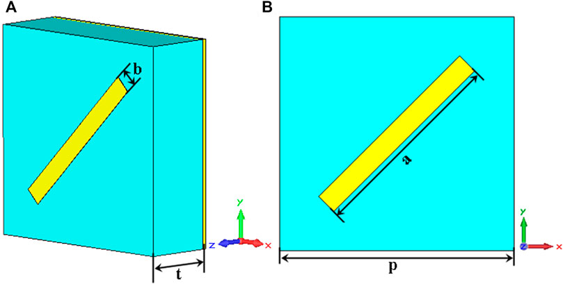
FIGURE 1. (A) Perspective view of the unit cell and (B) front view of the unit cell.
The performance of the polarization conversion metasurface is simulated with commercial software CST Microwave Studio TM 2015. The model was performed by the free space method. Thus, the boundary conditions are set as unit cells along the x axis and the y axis, the electromagnetic waves of the transverse electric (TE) or transverse magnetic (TM) are incident, and the directions of the electric field and the magnetic field are along the y(x) axis and the x(y) axis, respectively. Figure 2 shows the co-polarization and cross-polarization coefficients versus frequency under normal incidence. As shown in Figure 2, a strong cross-polarization reflection coefficient (rxy and ryx) occurs under both y-polarized and x-polarized normal incidences. Furthermore, the cross-polarization reflection band is very wide. The polarization conversion coefficient is above 90% from 9 GHz to 16.8 GHz for both y-polarized and x-polarized incident waves. We can see from Figures 2A,B that there are three distinct cross-polarization reflection peaks located at 9.2 GHz, 13 GHz, and 16.4 GHz, respectively. The cross-polarization reflection ratio reaches 95.8%, 96%, and 96% at 9.2 GHz, 13 GHz, and 16.4 GHz, respectively. Three plasmon resonance frequencies form the broadband polarization conversion.
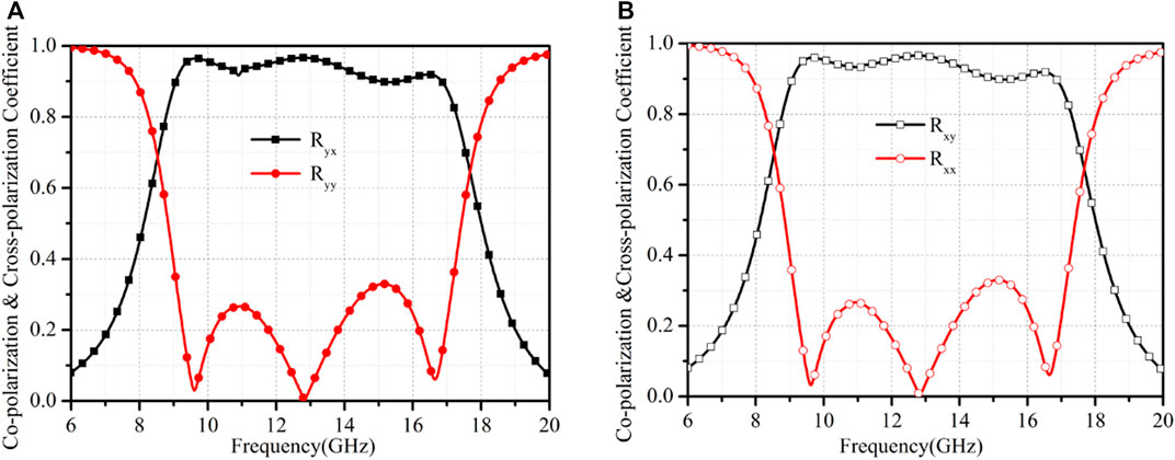
FIGURE 2. Simulated results of the co-polarization and cross-polarization reflections for (A) TE-polarized wave and (B) TM-polarized wave.
Theory analysis
In order to better understand the physical mechanism of the wide-band linear-to-linear polarization conversion, we first measured the permittivity of the Al2O3 ceramic at different temperatures with a pair of rectangle waveguides. The size of the sample is 22.86 × 10.16 × 2 mm3, and the measured frequency band is from 8.2 GHz o 12.4 GHz. The permittivity curve of the Al2O3 ceramic is about 8.3 in the tested frequency, as shown in Figure 3. Figure 3 shows that the permittivity of the Al2O3 ceramic exhibits temperature stability.
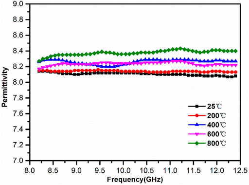
FIGURE 3. Permittivity of the Al2O3 ceramic with frequency at different temperatures.
Second, the physical mechanism of the wide-band linear-to-linear polarization conversion is the root of electric or magnetic resonance, so the surface currents are monitored at different resonant peaks, which can judge a resonance belonging to electric or magnetic resonance. Figure 3 gives the surface current distribution at 9.2 GHz, 13 GHz, and 16.4 GHz, respectively.
As shown in Figure 4, there exists an obvious near-field coupling between the cut wire and the metal background plane. Moreover, this near-field coupling forms electric resonance or magnetic resonance, so multi-resonances result in wide-band polarization conversion. We can see from Figure 4A that the surface current directions between the cut wire and the metallic background plane are opposite in the x-o-y plane at 9.2 GHz; this is equivalent to the current forming a closed-loop, which is like a magnetic dipole, so this resonance belongs to magnetic resonance. Because the surface current directions of Figure 4B between the cut wire and the metallic background plane are also opposite, surface current characteristics are the same as the first resonance, so the resonance type also belongs to magnetic resonance at 13 GHz. We can see from Figure 4C that the surface current directions are the same between the cut wire and the metallic background plane at 16.4 GHz, which is like an electric dipole oscillating back and forth, so this resonance belongs to electric resonance. Based on the aforementioned analysis, multi-resonances can expand the polarization conversion band.
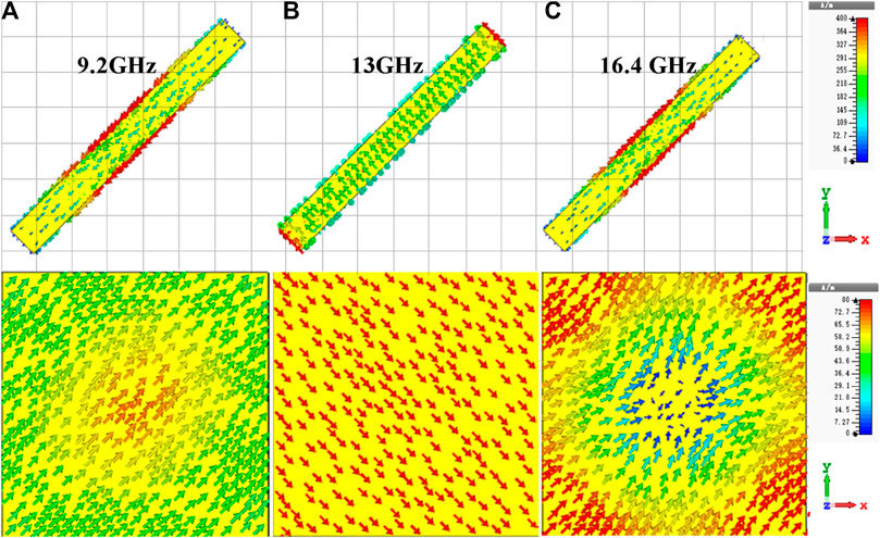
FIGURE 4. Surface current distributions of the cut wire and the metal back ground plane in the x-o-y plane.
Since the resonators have the capability of generating an abrupt phase change [27, 28], one can gain the phase difference required for RCS reduction. Based on the polarization conversion basic unit structure, we can acquire two elements with the same polarization conversion rate and 180° phase difference in a wider frequency by a suitable arrangement. Region 0 is composed of the 5*5 polarization conversion unit structure, as shown in Figure 5. Then, element 0 that rotated 90° is defined as element 1, as shown in Figure 5, so the dimensions of elements 0 and 1 are the same, as shown in Figure 5. The simulated polarization conversion rate of two elements is shown in Figure 5A, which shows that two elements have the same very high conversion rate in the same frequency band. Moreover, the simulated phase difference between the two elements is also close to 180° during the frequency band of 4 GHz–20 GHz, as shown in Figure 6B. Thus, the electromagnetic polarization conversion can be comprehensively utilized to suppress backward scattering in a wider frequency band. Here, it is worth discussing that the length and width of the cut wire are very important parameters for the polarization conversion rate and for determining the resonant frequency, thus determining the polarization conversion amplitude and phase, as shown in Figure 7 [26]. We can see from Figure 7 that the polarization conversion rate decreases, bandwidth increases, and resonant frequency changes when the length and width of the cut wires increase. Although the influence of the thickness of the Al2O3 ceramic is also important, as shown in Figure 7, Figure 7 shows that the polarization bandwidth moves to low frequency with the increase in thickness, and the resonant point also changes. So, the structural parameters of the element determine the polarization conversion amplitude and phase.
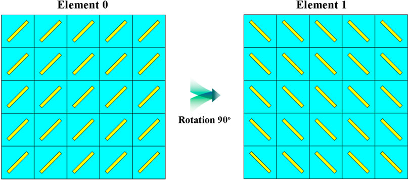
FIGURE 5. Elements of the metasurface element 0 and element 1.

FIGURE 6. Elements of the metasurface (A) reflection amplitudes and (B) phases of elements 0 and 1.
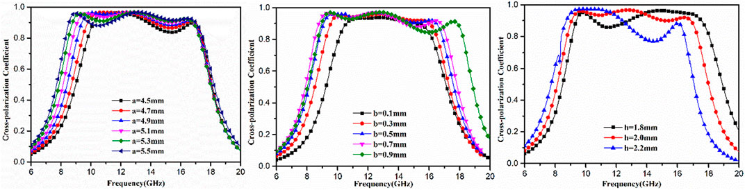
FIGURE 7. Simulated results of the cross-polarization reflections show that the length, width, and thickness of cut wires vary with frequency.
Based on the basic two elements, the checkboard metasurface is depicted in Figure 8A. The checkboard metasurface considered in this study consists of 6 × 6 elements, as shown in Figure 8A. Two elements are a subarray of 5 × 5 short silver wires shown in Figure 8A. The overall sizes of the proposed metasurfaces are 180 × 180 mm2. In order to validate the RCS reduction characteristics of the metasurface, RCS reduction was simulated under normal incidence, as shown in Figure 8B. In the simulation, the open boundary condition was set in the x, y, and z directions, and a plane wave usually occurred on the chessboard metasurface. The three-dimensional scattered far fields were simulated at the frequencies of 9.0 GHz, 12.0 GHz, 14.0 GHz, and 16.0 GHz, as depicted in Figure 9. As expected, incident waves are mainly reflected in four directions, leading to four oblique beams. In this case, echo waves along with the normal of the metasurface are reduced, and thus, the mono-static RCS can be reduced.
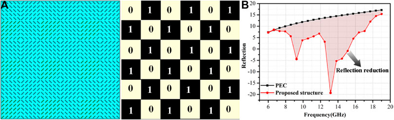
FIGURE 8. (A) Chessboard structure consisting of 6*6 sub-elements; (B) simulated reflection spectra of the PEC and RCS for the chessboard structure.
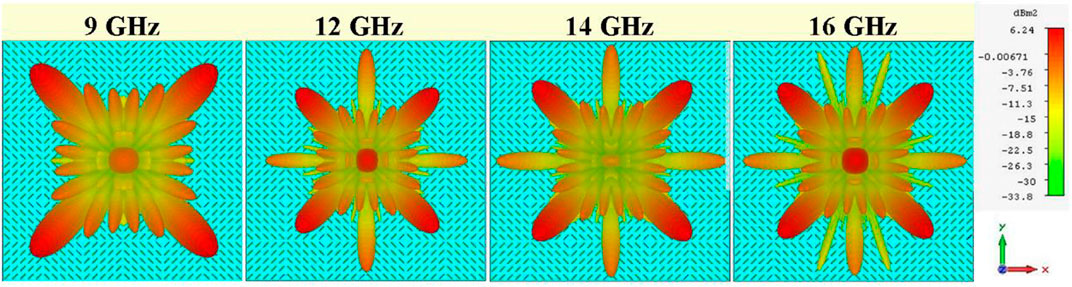
FIGURE 9. Three-dimensional scattering patterns of the chessboard metasurface.
Experimental verification
In order to further verify the design, a prototype with the size of 180*180 mm2 was fabricated using the printed circuit board technique, which is measured in an anechoic chamber. In the fabrication process, the high-temperature-resistant Al2O3 ceramics serve as the dielectric substrate, then silver glue with 4.52 × 10⁷ S/m was printed on the surface of the Al2O3 ceramic with a thickness of 2 mm by means of the silk screen printed technology, and then the chessboard metasurface of silver was obtained. At last, the silver glue was printed on the other side of the Al2O3 ceramic as a metal ground plate to prevent EM waves from leaking out, and the complete fabricated sample was successfully presented. The proposed polarization conversion metasurface and chessboard metasurface were finally achieved, as shown in Figures 10A,B, respectively. In the course of the experiment, the metal base is heated by resistance, quickly increasing to the measured temperature, and then holding for 30 min. The measurement system is based on the Agilent 8720ET analyzer with broadband rectangular horn antennas, as shown in Figure 10A. The measuring frequency band covers from 7 GHz to 18 GHz. The sample is irradiated by the TE wave by one of the two horn antennas, while the other antenna receives the TM reflected wave. In order to carry out the normal incidence measurement in the experiment, the separation angle between the two antennas is very small. The horn antenna can receive TM by placing the receiving antenna on its longer side. The cross-polarization reflections can be measured and obtained, as shown in Figure 10A. The measured cross-polarization reflection is in basic accordance with the simulation results when considering the error. Compared with the simulated results, the bandwidth of cross-polarization reflection is also very wide. However, the polarization conversion frequency band moves to a low frequency compared with the simulated results. Moreover, the cross-polarization reflection decreases with the temperature increase, this error is a little larger than the simulation. Several reasons can result in discrepancies. One explanation is that the sample is too small for measuring the frequency band, which causes a major error in the test. The second reason is the permittivity difference at 26°C, 500°C, and 800°C, as shown in Figure 3. In addition, the process error is also another factor influencing the results. Based on the aforementioned analysis, the measured result is in basic agreement with the simulated results when considering these factors. Since the measurement was performed under normal incidence, the reflection reduction can be approximately regarded as RCS reduction, as shown in Figure 10B. We also found out that the measured reflection reduction level is increased in a broad frequency band with temperature increasing. As a consequence, the measured reflection reduction at room temperature is less than the other two temperatures. However, the measured results show a broadband reflection reduction feature as expected. Thus, the influence of the defects on the RCS reduction performance was mainly due to the size of our sample.
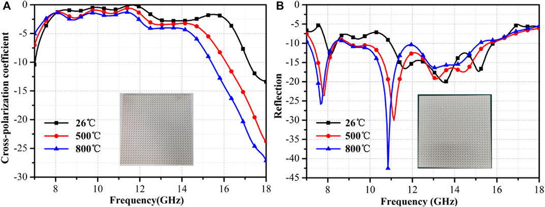
FIGURE 10. (A) Measured cross-polarization coefficients for the TE-polarized wave and (B) measured reflection results for RCS reduction.
Conclusion
In summary, we have proposed a broadband polarization conversion at high temperatures based on the classical cut wires. Using the cut wire structure can achieve more than 90% polarization conversion rate from 9.0 GHz to 16.8 GHz at 800°C. Two polarization waves can obtain the same conversion rate. We have also demonstrated the the checkerboard metasurface based on the cut wire structure for broadband RCS reduction caused by the phase cancellation mechanism. The cut wires in different directions provide an abrupt phase change. By designing the phase spatial profiles of the scattering surfaces, we can reduce the normalized reflection by less than 0.1 in the frequency band of 9 GHz–16.8 GHz. Finally, we also measured the sample and demonstrated our proposed structure. The proposed metasurface has also the advantages of low cost and easy fabrication. Given those, our study provides an alternative and effective way for RCS reduction.
Data availability statement
The original contributions presented in the study are included in the article/Supplementary Materials, further inquiries can be directed to the corresponding authors.
Author contributions
Conceptualization, SQ; formal analysis, YL; funding acquisition, WW and LZ; investigation, JJ; methodology, WW and JW; writing—original draft, CX; and writing—review and editing, YM and JL.
Funding
This work is supported by the National Natural Science Foundation of China (Grant Nos. 61801509, 52272101, 61971435, 12004437, and 61971437) and the Natural Science Foundation of Shanxi Province (Grant Nos.2020JM-342, 2022JQ-630, and 2022JM-352).
Conflict of interest
The authors declare that the research was conducted in the absence of any commercial or financial relationships that could be construed as a potential conflict of interest.
Publisher’s note
All claims expressed in this article are solely those of the authors and do not necessarily represent those of their affiliated organizations, or those of the publisher, the editors, and the reviewers. Any product that may be evaluated in this article, or claim that may be made by its manufacturer, is not guaranteed or endorsed by the publisher.
References
1. Cui G, Liu Y, Gong S. A novel fractal patch antenna with low RCS. J Electromagn Waves Appl (2007) 21(15):2403–11. doi:10.1163/156939307783134335
2. Knott EF, Shaeffer JF, Tuley MT. Radar cross section. 2nd ed. United States: SciTech. Publishing (2004).
3. Engheta N. Thin absorbing screens using metamaterial surfaces. Proc IEEE Antennas Wirel Propag Lett (2002) 2:392–5. doi:10.1109/APS.2002.1016106
4. Mosallaei H, Sarabandi K. A one-layer ultra-thin meta-surface absorber. IEEE Antennas Wirel Propag Lett (2005) 1:615–8. doi:10.1109/APS.2005.1551634
5. Pullar RC. Hexagonal ferrites: A review of the synthesis, properties and applications of hexaferrite ceramics. Prog Mater Sci (2012) 7:1191–334. doi:10.1016/j.pmatsci.2012.04.001
6. Houbi A, Aldashevich ZA, Atassi Y, Bagasharova Telmanovna Z, Saule M, Kubanych K. Microwave absorbing properties of ferrites and their composites: A review. J Magn Magn Mater (2021) 529:167839. doi:10.1016/j.jmmm.2021.167839
7. Lei L, Yao ZJ, Zhou JT, Wei B, Fan HY. 3D printing of carbon black/polypropylene composites with excellent microwave absorption performance. Compos Sci Technol (2020) 200:108479. doi:10.1016/j.compscitech.2020.108479
8. Chen XJ, Liu HY, Hu DC, Liu HQ, Ma WS. Recent advances in carbon nanotubes-based microwave absorbing composites. Ceram Int (2021) 47:23749–61. doi:10.1016/j.ceramint.2021.05.219
9. Micheli D, Pastore R, Apollo C, Marchetti M, Gradoni G, Primiani VM, et al. Broadband electromagnetic absorbers using carbon nanostructurebased composites. IEEE Trans Microw Theor Tech (2011) 59:2633–46. doi:10.1109/tmtt.2011.2160198
10. De Rosa IM, Mancinelli R, Sarasini F, Sarto MS, Tamburrano A. Electromagnetic design and realization of innovative fiber-reinforced broad-band absorbing screens. IEEE Trans Electromagn Compat (2009) 59:700–7. doi:10.1109/temc.2009.2018125
11. Lee SE, Lee WJ, Oh KS, Kim CG. Broadband all fiber-reinforced composite radar absorbing structure integrated by inductive frequency selective carbon fiber fabric and carbon-nanotube-loaded glass fabrics. Carbon (2016) 107:564–72. doi:10.1016/j.carbon.2016.06.005
12. Xie S, Ji ZJ, Li B, Zhu LC, Wang J. Electromagnetic wave absorption properties of helical carbon fibers and expanded glass beads filled cement-based composites. Composites A: Appl Sci Manufacturing (2018) 114:360–7. doi:10.1016/j.compositesa.2018.08.034
13. Liu Q, Cao B, Feng C, Zhang W, Zhu S, Zhang D. High permittivity and microwave absorption of porous graphitic carbons encapsulating Fe nanoparticles. Compos Sci Technol (2012) 13:1632–6. doi:10.1016/j.compscitech.2012.06.022
14. Quan L, Qin F, Estevez D, Wang H, Peng H. Magnetic graphene for microwave absorbing application: Towards the lightest graphene-based absorber. Carbon (2017) 125:630–9. doi:10.1016/j.carbon.2017.09.101
15. Liu XG, Li B, Geng DY, Cui WB, Yang F, Xie ZG, et al. (Fe, Ni)/C nanocapsules for electromagnetic-wave-absorber in the whole Ku-band. Carbon (2009) 47:470–4. doi:10.1016/j.carbon.2008.10.028
16. Hou Y, Cheng L, Zhang Y, Yang Y, Deng C, Yang Z, et al. Electrospinning of Fe/SiC hybrid fibers for highly efficient microwave absorption. ACS Appl Mater Inter (2017) 8:7265–71. doi:10.1021/acsami.6b15721
17. Li R, Qing YC, Li W, Li Y. The electromagnetic absorbing properties of plasma-sprayed TiC/Al2O3 coatings under oblique incident microwave irradiation. Ceram Int (2021) 47:22864–8. doi:10.1016/j.ceramint.2021.04.306
18. Zhou YY, Yang CQ, Li R, Chen D, Ren ZW, Lu YY, et al. Ultra-thin Al2O3-Sr(1-x)GdxTiO3 composite ceramics with high microwave absorption performance. J Mater Sci Mater Electron (2021) 32:8788–97. doi:10.1007/s10854-021-05550-0
19. Yang Z, Luo F, Hu Y, Duan S, Zhu D, Zhou W. Dielectric and microwave absorption properties of TiO2/Al2O3 coatings and improved microwave absorption by FSS incorporation. J Alloys Compd (2016) 678:527–32. doi:10.1016/j.jallcom.2016.04.031
20. Yang Z, Luo F, Zhou W, Jia H, Zhu D. Design of a thin and broadband microwave absorber using double layer frequency selective surface. J Alloys Compd (2017) 699:534–9. doi:10.1016/j.jallcom.2017.01.019
21. Yu N, Genevet P, Kats MA, Aieta F, Tetienne JP, Capasso F, et al. Light propagation with phase discontinuities: Generalized laws of reflection and refraction. Science (2011) 334(6054):333–7. doi:10.1126/science.1210713
22. Sun S, He Q, Xiao S, Xu Q, Li X, Zhou L. Gradient-index meta-surfaces as a bridge linking propagating waves and surface waves. Nat Mater (2012) 11(5):426–31. doi:10.1038/nmat3292
23. Huang L, Chen X, Mühlenbernd H, Li G, Bai B, Tan Q, et al. Dispersionless phase discontinuities for controlling light propagation. Nano Lett (2012) 12(11):5750–5. doi:10.1021/nl303031j
24. Pors A, Bozhevolnyi SI. Plasmonic metasurfaces for efficient phase control in reflection. Opt Express (2013) 21(22):27438–51. doi:10.1364/oe.21.027438
25. Pfeiffer C, Grbic A. Metamaterial Huygens’ surfaces: Tailoring wave fronts with reflectionless sheets. Phys Rev Lett (2013) 110(19):197401. doi:10.1103/physrevlett.110.197401
26. Artiga X, Bresciani D, Legay H, Perruisseau-Carrier MJ. Polarimetric control of reflective metasurfaces. IEEE Antennas Wirel Propag Lett (2012) 11:1489–92. doi:10.1109/lawp.2012.2231045
27. Grady NK, Heyes JE, Chowdhury DR, Zeng Y, Reiten MT, Azad AK, et al. Terahertz metamaterials for linear polarization conversion and anomalous refraction. Science (2013) 340(6138):1304–7. doi:10.1126/science.1235399
28. Zhao Y, Alù A. Manipulating light polarization with ultrathin plasmonic metasurfaces. Phys Rev B (2011) 84(20):205428. doi:10.1103/physrevb.84.205428
29. Zhu HL, Cheung SW, Chung KL, Yuk TI. Linear-to-circular polarization conversion using metasurface. IEEE Trans Antennas Propag (2013) 61(9):4615–23. doi:10.1109/tap.2013.2267712
30. Wu S, Zhang Z, Zhang Y, Zhang K, Zhou L, Zhang X, et al. Enhanced rotation of the polarization of a light beam transmitted through a silver film with an array of PerforatedS-shaped holes. Phys Rev Lett (2013) 110(20):207401. doi:10.1103/physrevlett.110.207401
Keywords: high temperature-resistant, wideband RCS reduction, chessboard metasurface, Al2O3 ceramic, surface current
Citation: Wang W, Jiang J, Liang J, Zheng L, Meng Y, Li Y, Xu C, Wang J and Qu S (2022) High-temperature metasurface for polarization conversion and RCS reduction. Front. Phys. 10:1061807. doi: 10.3389/fphy.2022.1061807
Received: 05 October 2022; Accepted: 14 October 2022;
Published: 31 October 2022.
Edited by:
Yuancheng Fan, Northwestern Polytechnical University, ChinaReviewed by:
Ke Chen, Nanjing University, ChinaKaiyang Cheng, Dongguan University of Technology, China
Quanhong Fu, Northwestern Polytechnical University, China
Copyright © 2022 Wang, Jiang, Liang, Zheng, Meng, Li, Xu, Wang and Qu. This is an open-access article distributed under the terms of the Creative Commons Attribution License (CC BY). The use, distribution or reproduction in other forums is permitted, provided the original author(s) and the copyright owner(s) are credited and that the original publication in this journal is cited, in accordance with accepted academic practice. No use, distribution or reproduction is permitted which does not comply with these terms.
*Correspondence: Wenjie Wang, d3dqaWUyMDA1QDE2My5jb20=; Jinming Jiang, ODhqaWFuZ2ppbm1pbmdAMTYzLmNvbQ==; Jiangang Liang, Y2F0LWxpYW5nMTk3NUAxNjMuY29t