 Janusz Gołdasz
 Bogdan Sapiński
 Łukasz Jastrzębski
 Michal Kubik
- 1Faculty of Electrical and Computer Engineering, Cracow University of Technology, Kraków, Poland
- 2BWI Technical Center, BWI Group, Kraków, Poland
- 3Department of Process Control, AGH University of Science and Technology, Kraków, Poland
- 4Faculty of Mechanical Engineering, Brno University of Technology, Brno, Czechia
This study concerns the modeling of the hysteretic behavior of magnetorheological (MR) dampers. In general, hysteresis is one of key factors influencing the output of such actuators. So far, more attention has been paid to studying the combined hysteretic behavior of MR actuators by observing the relationships between the output (force/torque) and the inputs (current, velocity, and position). However, these devices feature two distinct hysteretic mechanisms: mechanical/hydraulic and magnetic. The mechanical hysteresis is of different nature than the magnetic hysteresis due to the properties of ferromagnetic materials forming the actuator's electromagnet circuit, and these should be split in the modeling process. In the present study, we separate the magnetic hysteresis from the mechanical/hydraulic one by investigating the magnetic flux vs. exciting current relationship of a commercial flow-mode MR damper subjected to sinusoidal current loading and independently of the mechanical excitations. The resulting behavior of the electromagnetic circuit is then examined using the non-linear inductor approach with hysteresis. Total hysteresis is then modeled using a non-linear inductor model in combination with a phenomenological parametric Maxwell type model of the damper.
1. Introduction
Magnetorheological (MR) fluids are well-known representatives of so-called smart materials. The material develops a yield stress when exposed to magnetic field (Rabinow, 1948), and it has been successfully used in commercial applications, i.e., semi-active vehicle dampers or powertrain mounts (Jolly et al., 1999).
Fundamentally, a typical MR flow-mode/shear-mode damper features an internal control valve in the form of an electromagnet with a fixed height planar/annular flow channel. The electromagnet's core contains a coil assembly. Supplying the electrical current to the coil results in inducing magnetic field in the flow channel, thus activating the fluid. The effect is a resistance-to-flow build-up manifested by changes in the output force or torque. The effect is reversible and fast. At the same time, various factors make the conversion process complicated (Gołdasz et al., 2018a), namely, temperature, friction, material's liability to sedimentation, non-linear magnetization characteristics of the materials of which the damper's magnetic circuit is built, magnetic hysteresis, mechanical hysteresis, current driver dynamics, control coil dynamics, non-linear relationship between the magnetic flux and the field-dependent yield stress, etc. (Kubik et al., 2017). Generally, the contributors make the control algorithm development process a challenge and the optimal control algorithm difficult or impossible to obtain. Of the above contributors, the magnetic hysteresis is present virtually in any ferromagnetic material, though on a different scale. Although the electromagnetic circuits of MR valves are usually developed with soft magnetic alloys, the flux's hysteresis should be accounted for in engineering an MR damper-based control system. As MR dampers are by principle solenoid actuators (in which the topic has been subject to extensive research, Mayergoyz et al., 1989), the significance of hysteresis is similarly important. In latching two-position solenoids, for instance, the hysteresis and the residual magnetism affect the control circuit's capacity to maintain the solenoids at a given position. In MR dampers the hysteresis complicates controlling the output of these devices, and residual forces have a usually negative impact on the damper's output at off-state forces in particular.
In literature, magnetic hysteresis models are classified into two groups (Mazgaj, 2010). The first one includes energy-based models of which the Stoner-Wohlfart (S-W) model or Jiles-Atherton (J-A) model are the most well-known representatives (Jiles and Atherton, 1984). The other class incorporates the so-called phenomenological models of Preisach (Mayergoyz and Friedman, 1988; Mayergoyz et al., 1989), Duhem/Hodgdon-Coleman (Macki et al., 1993) or Chua (Chua and Stromsmoe, 1970). For this study, we chose one representative of the phenomenological group—the Duhem model.
The contribution of hysteresis to the force output of MR dampers has been recognized rather early (Dyke et al., 1996). Following on from Dyke et al., numerous phenomenological or lumped parameter models have been developed and applied for the purpose of predicting the hysteretic output of MR dampers (Wang and Liao, 2011). Typical approach involved studying the relationship between force/torque vs. input current and displacement/velocity and then fitting a particular model to damper data from experiments. With such a methodology, only total hysteresis can be studied. Few authors attempted to analyze the magnetic hysteresis independently of other hysteretic contributors (Szczygłowski, 2001; An and Kwon, 2003; Zheng et al., 2015; Guo et al., 2018; Li et al., 2019). The mechanical/hydraulic hysteresis has its origin in flow mechanics due to the fluid's compressibility and the lumped fluid mass (inertia) traveling back and forth through the annulus (Gołdasz and Alexandridis, 2012). For comparison, the magnetic hysteresis is an inherent property of ferromagnetic materials and does not disappear in the DC limit, which is what the hydraulic hysteresis does. Including the magnetic hysteresis operator, therefore, brings numerous benefits. First, it facilitates control through either sensor-based or sensorless approach as proven with other electrical actuators and drives (Erol et al., 2012). The implementation of the magnetic hysteresis operator will allow for a model-based control, too. Second, it allows taking into account the effects already in the design process. For instance, Kubik and Gołdasz (2019), in the parametric study on the MR damper dynamic behavior with the so-called vector hysteresis approach, showed that the use of such models may yield improvements in understanding the MR damper physics and deliver a better product. Simply analyzing prior art, e.g., the study of hysteresis of an MR brake as in An and Kwon (2003) accomplished with the Hodgdon model highlights significant advantages in predicting the output of the brake on including the magnetic hysteretic operator.
In general, the purpose of the study is to present means for distinguishing the contribution of particular hysteretic operators to the output of MR dampers. To accomplish the goal, we reconstruct the magnetic behavior of a long-stroke flow-mode MR damper with one magnetic hysteretic operator to obtain the induced flux variation against the exciting current. The sensorless flux reconstruction technique we used allows inspection of the damper's magnetic hysteretic behavior without any knowledge of its internals. Finally, a first-order phenomenological damping force model based on a Maxwell model is employed to explore the contribution of the remaining mechanisms.
The paper is organized as follows. Section 2 contains the description of the dual hysteresis model concept of an MR damper. In the section we describe both the magnetic hysteretic operator and the mechanical model. Furthermore, in section 3, we explain the test setup and the hardware used. Next, section 4 presents model identification results and a comparison of the hysteretic models' performance against selected experimental data sets. Finally, conclusions are presented in section 5.
2. Damper Modeling
To predict the hysteretic behavior of a typical single-tube flow-mode MR damper as in Figure 1, we developed a phenomenological model of the device. The cylinder tube houses a piston assembly that separates the fluid volumes into the upper (rebound) volume and the lower (compression) volume. The floating gas cup separates the compression chamber from pressurized gas for volume compensation. The piston features a solenoid with a fixed-height annular gap for magnetizing the MR fluid flowing through it as in Figure 1. There is a thru-rod electrical connection between the current driver (not shown) and the coil. The induced flux travels across the core, the annular gap, the ring and the cylinder tube to return to the core through the annular gap again. As illustrated, there is also a flux leakage path from the tube through the MR fluid and the rod.
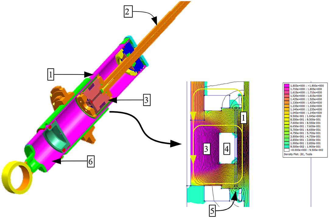
Figure 1. MR vehicle suspension damper and exemplary flux density map (piston assembly); 1-cylinder and ring, 2-rod, 3-core, 4-coil assembly, 5-annulus, and 6-gas chamber.
Specifically, we model viscous losses, friction, and offset force due to the accumulator. Moreover, we assume the model would capture the effects of fluid compressibility, field-dependent pressure drop, as well as basic dynamics of the MR actuator's electromagnet although in a simplified manner. The model incorporates two fundamental components reflecting the force build-up process in the actuator: the electromagnet model and the MR effect model.
First, the dynamics of the electromagnet is captured with a non-linear hysteretic inductor concept. The model can be analyzed by looking up the relationship between the exciting (magnetizing) current and the resulting induced flux (linkage). Second, the behavior of the fluid is examined further with a first-order phenomenological model of the damping force. The inductor model and the force model are related by a non-linear flux-to-force coupling.
2.1. Non-linear Inductor Modeling With Hysteresis
Let us consider the simplest non-linear lumped parameter model of an MR actuator as shown in Figure 2. The model includes the input voltage source u(t), the coil resistance Rc, and the non-linear inductance L(i) in series with the resistor. The model equation is then as follows:
where u – supply voltage, i – coil current, and λ = L(i)i – magnetic flux linkage, and L(i) – coil inductance. Equation (1) represents the dynamics of a simple non-linear inductor. The relationship λ(i) can be further expanded to include other phenomena.
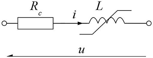
Figure 2. Block diagram of the proposed inductor model—reproduced from Gołdasz et al. (2018a) under the CC BY 4.0 license.
In the presented form the model copies the average flux induced in the electromagnet, and its parameters can be estimated independently of the hysteretic force component. Equation (1) may represent a simple non-linear inductor model with no hysteresis or assume more complex forms. In the present study we chose to proceed with the Duhem hysteresis model.
2.2. Duhem Model
The relationship between the flux linkage λ and the coil current i of the inductor in Figure 2 can be described using the following Duhem hysteresis operator (Mayergoyz et al., 1989)
We select the shape functions f(i) and g(i) as follows:
The model incorporates a set of four tuning parameters (a, b1, b2, d), which can be identified from experimental data. In the study, we assume the parameters are current dependent—the examined object is non-linear. Typical identification procedures rely on fitting the model to measurements as demonstrated by Chwastek and Szczygłowski (2008) or Gołdasz et al. (2019), usually by means of least-squares quality metrics. The Duhem model parameters are not directly related to the material's physical properties, e.g., remanence, coercivity, contrary to the famous Jiles-Atherton model, for instance. In the anhysteretic case (a = 0) the inductor model reduces to that of a non-linear one without hysteresis, i.e., λ = d(i)i. Then, an initial estimate of the parameter d at a given current level can be provided from coil inductance calculations using lumped parameter models or more advanced finite-element techniques, for example. Once the parameter d is fixed, the parameters a and b1 can be played with to arrive at the correct hysteresis width. Finally, the rate tuning parameter b2 of the hyperbolic tangent function can be adjusted to match the λ−i curve's slope. The particular form of the shape function was preferred for consistency and ease of use.
The model parameter set can then be used for varying the hysteresis width and shape. In Figure 3, the authors reveal the impact that each parameter of the model has on the λ−i normalized loop shape; the arrow in each figure shows the direction of particular parameter increase. In the normalized plots, the flux and current variation range is from −1 to 1.
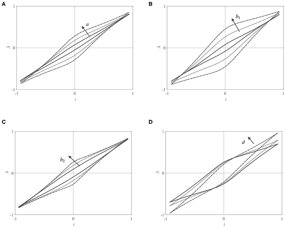
Figure 3. (A–D) Duhem model: impact of model parameters on the normalized λ−i loop.
In this context, the Duhem operator is a non-linear system model driven by the coil current i. Its output is the flux linkage λ(t). In the analyzed form, the Duhem model has the advantage over other hysteretic models, e.g., the Bouc-Wen model, for being less complex, as it accepts half of the parameters (that the standard Bouc-Wen model requires) for successful operation as shown in Gołdasz et al. (2018b).
2.3. Phenomenological Model of an MR Damper
Next, we examine the simplest first-order Maxwell model incorporating a non-linear dashpot in series with a spring. The model is assumed to ignore higher-order dynamics due to mass effects. Only the compressibility of fluid chambers is taken into account as main contributor to the damper hysteresis. The non-linear Maxwell model is functionally identical to the model examined by Gołdasz and Alexandridis (2012) as well as Simms et al. (2004). As a partial proof, let us then consider the cylinder housing with an MR valve located in the piston as in Figure 4. The piston is driven by the prescribed displacement x(t), thus forcing the fluid through the valve at the volumetric rate Q. The pressure drop across the piston is Δp = P1−P2. Considering the variation of pressures in each fluid chamber, we yield
where β-bulk modulus. Assuming the volumes V1 = V2 = V and transforming the above system of equations gives
where A is the piston cross-section area. In general, the pressure drop across the MR valve and the flow rate are related by a generic non-linear function Q = f(Δp, λ). By way of simplification, we further assume Q = Δp/R(λ) and R = R(λ) is field-dependent hydraulic resistance (which further reduces to a (non)linear hydraulic resistance in the absence of flux). Substitution then gives
or multiplying by the piston cross-section area to get the output force F yields
This can be rewritten into a more generic form as follows:
where ζ is the field-dependent time constant. As an example, we represent the force shape function Fd to be
where the force component Fv represents viscous losses proportional to the velocity ẋ, Rv denotes hydraulic resistance due to viscous losses, Fλ copies the field-dependent force due to the MR effect. is a link between the damping force model and the inductor model. The model may incorporate friction force as well as force offset due to the presence of the pressurized accumulator. Moreover, c defines the force increase rate against the velocity ẋ. The model's simple form, as shown in Figure 5, is particularly convenient in model/parameter identification problems; the parameter kd represents all compliances present in the damper. Note that if fixed flux input is assumed, then the effect of force evolution against the velocity may be easily analyzed independently of the other excitations. Under time-varying current excitations, the flux build-up is copied by the inductor component, including a relevant hysteretic operator (see Equation 1), whereas the force change against the flux (as well as the velocity ẋ and the displacement x) is taken care of by Equation (8).
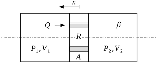
Figure 4. MR damper simplified layout.
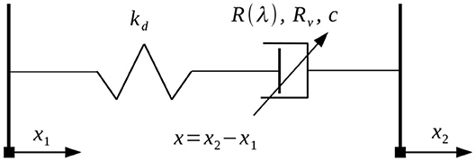
Figure 5. Block diagram of the hysteretic model (gas force not shown); x1, x2—displacements.
As shown, the model parameters can be deduced from the damper's geometry and material properties. However, due to unknown internals of the tested commercial MR damper, we estimate them from damping force measurements.
3. Test Inputs and Hardware
The model requires measurements of quantities from which the investigated models can be identified and their parameters estimated, namely, flux and force. Although both could be estimated simultaneously, and all measurements were carried out at the same time, we decided to rely on the sequential approach. First, to acquire the λ−i relationship for the damper, magnetic flux was extracted from voltage and current data via integration (and high-pass filtering for drift removal). The measurements were accomplished over a 20 s time span and by sampling the data at the frequency of 1 kHz. The data acquisition system was under the control of an AD/DA I/O board. The tested unit was a flow-mode linear commercial damper by BWI Group for a passenger car featuring an MR valve with one annular gap and one coil assembly. The long-stroke damper's coil resistance is appr. 1.1 Ω incl. electrical connections, and the device can be operated up to 5 A. More detailed information on the tested damper incl. transient response, frequency response and other characteristics can be found in Jastrzębski and Sapiński (2017), and the reader should refer to these for further details.
The damper was tested on a mechanical MTS810 shaker, and the displacement was acquired from the stroker's internal sensor, see Figure 6. In our experiments, the damper was subjected to constant velocity (triangular displacement) inputs using the above 1 Hz sine wave current input superimposed on the displacement profile x(t) as in Figure 7A. The peak-to-peak displacement was 150 mm, and the triangular displacement wave frequency was set to be 0.5 Hz. During the experiments, the input voltage was adjusted to result in peak coil currents I = {1, 1.5, 2, 2.5, 3, and 3.5} A. The magnetic flux time histories were then reconstructed as already mentioned.
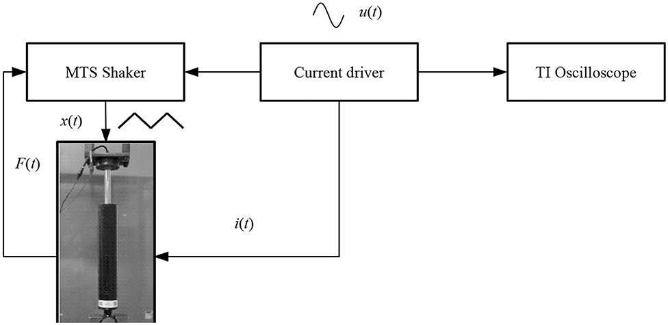
Figure 6. Damper test rig layout.
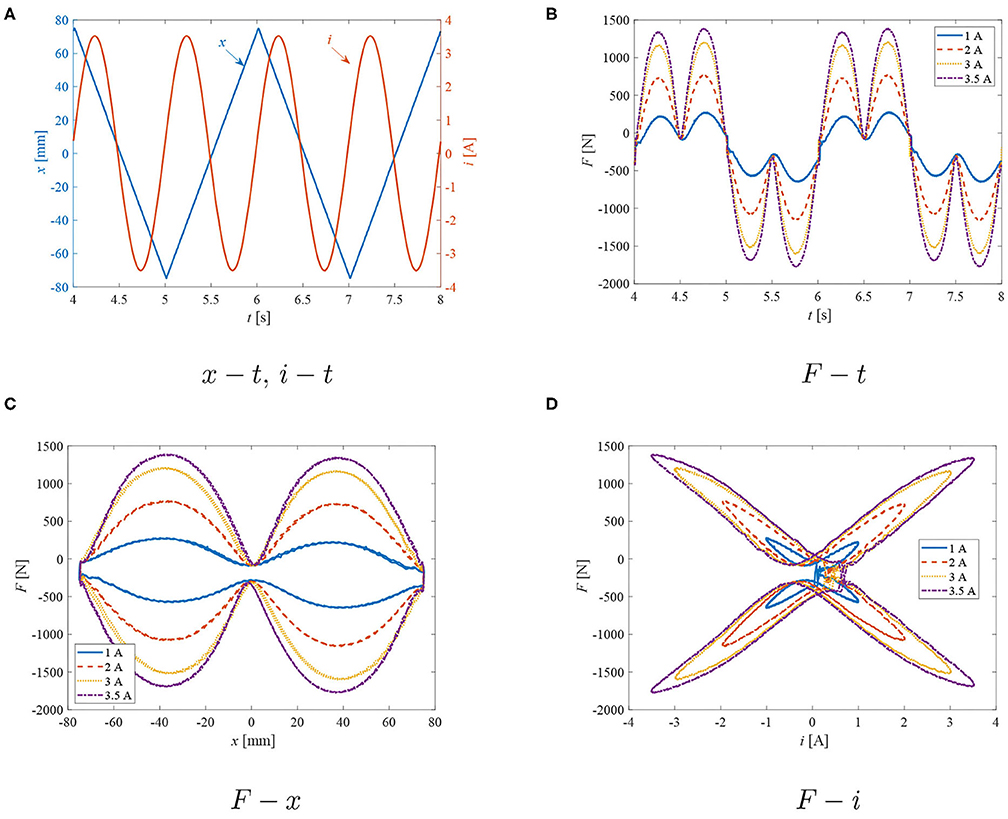
Figure 7. Test results: exemplary excitation inputs, time histories of force, force-displacement, and force-current loops. (A) x −t, i −t. (B) F −t. (C) F − x. (D) F −i.
4. Results and Discussion
Below, we show the obtained experimental results and then apply the proposed model for predicting the dampers characteristics.
Damper measurement results are highlighted in Figures 7–13. In particular, Figure 7A contains an exemplary time history of the excitation inputs (displacement, current) plotted over a selected 4 s time span. In Figure 7B, we plot time histories of the damping force corresponding to the abovementioned current peak levels. The results are complemented by the plots of the damping force vs. the input displacement in Figure 7C and the damping force vs. the measured coil current in Figure 7D. In the plots, the damping force is offset by the gas force due to the pressurized accumulator present in the monotube damper; the commercial damper was gas-charged at P0= 2.6 MPa. The gas pressure was measured at mid-stroke. The gas volume was estimated by pushing the piston rod downwards from a fully extended position (full rebound) to the fully collapsed one (full compression). The other bias force which can be observed in the data is friction (determined directly from the experimental data—Fr ≈ 70 N). The viscous damping coefficient was estimated by plotting the force vs. velocity at zero current condition. Furthermore, the flux linkage information was acquired by post-processing voltage and current as already mentioned; the flux integration procedure was applied for predicting the magnetic hysteresis of an MR damper and explained in detail in Gołdasz et al. (2019). There are several unavoidable issues with flux integration. First, the flux's initial value was unknown; that issue was solved by demagnetizing the damper after each measurement. Second, as the damper is stroked and/or the current is applied to the coil, the internal temperature increases. As a result, the coil resistance varies with temperature; the issue could be solved by, for example, using a sensory coil wrapped around the core, though this was not possible due to a lack of access to the internals of the damper. Third, measurement noise and integration errors are further accumulated in the process resulting in the flux linkage signal drift. That issue was at least partially solved by filtering to remove the signal bias and trend/drift. These issues may have influenced the outcome of the study.
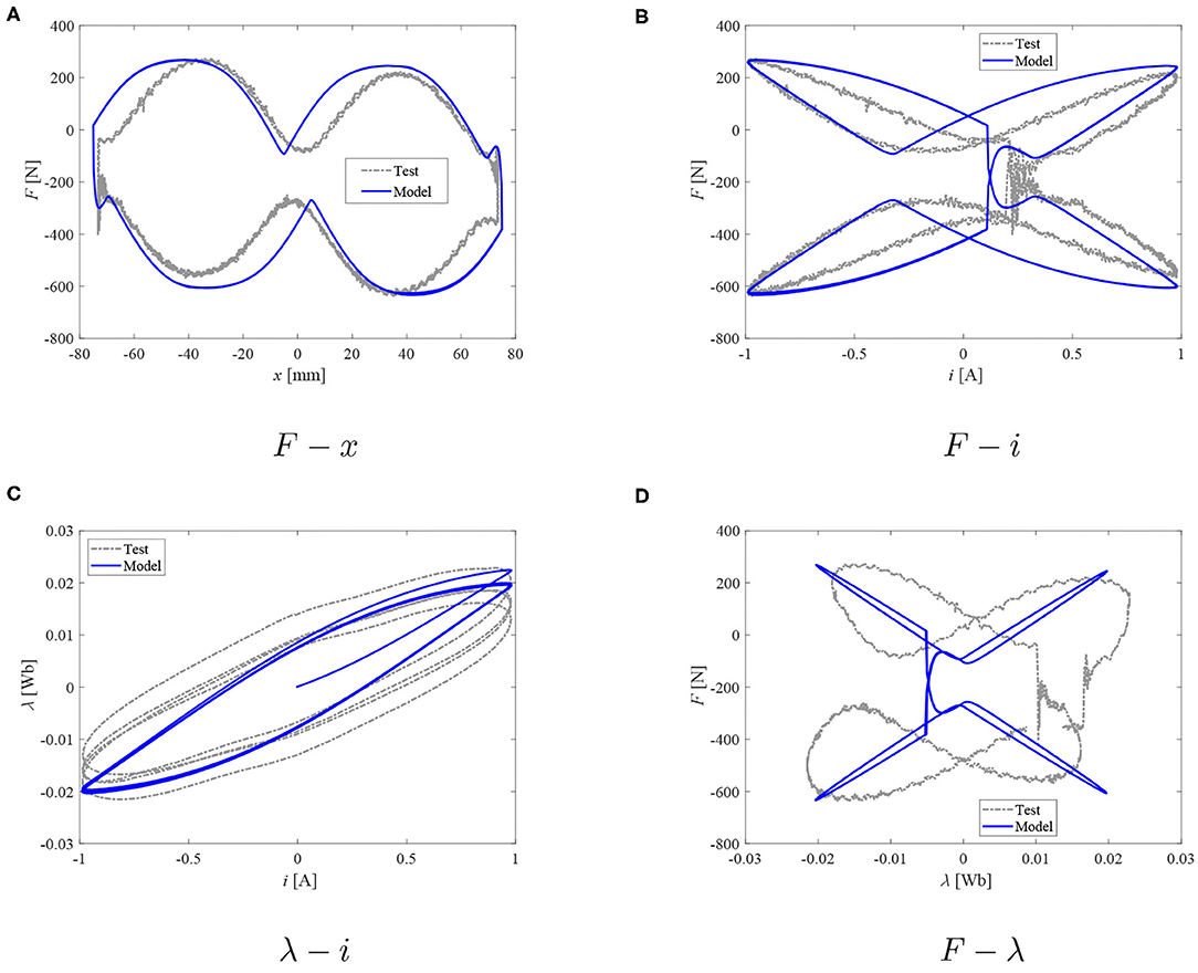
Figure 8. Damper model: measured force and reconstructed flux vs. model data; peak current I = 1.0 A. (A) F − x. (B) F − i. (C) λ −i. (D) F − λ.
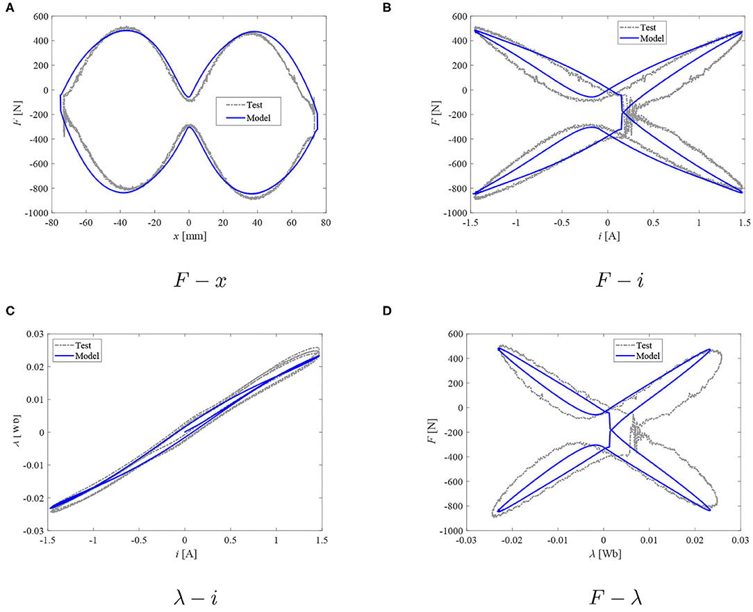
Figure 9. Damper model: measured force and reconstructed flux vs. model data; I = 1.5 A. (A) F − x. (B) F − i. (C) λ −i. (D) F − λ.
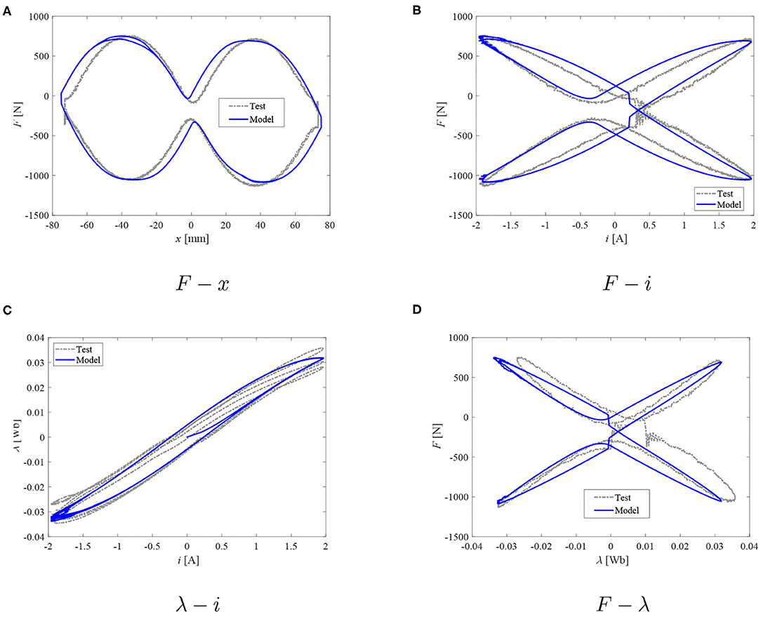
Figure 10. Damper model: measured force and reconstructed flux vs. model data; I = 2.0 A. (A) F − x. (B) F − i. (C) λ −i. (D) F − λ.
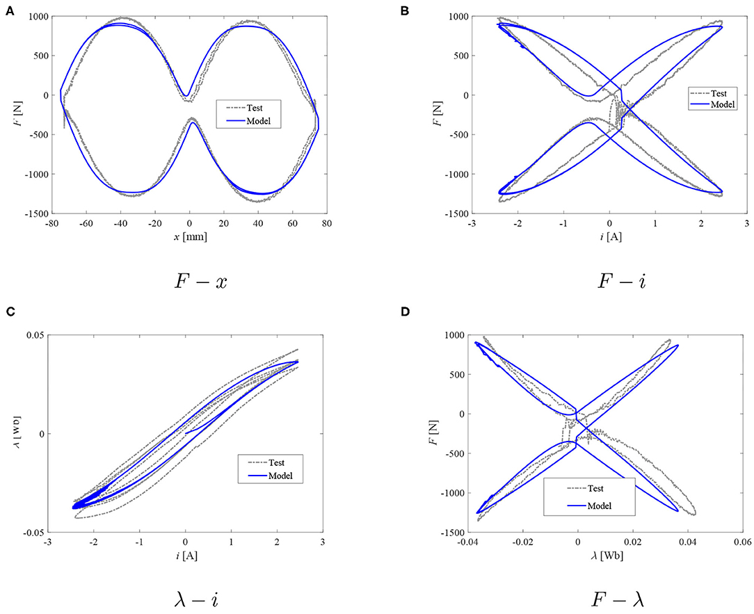
Figure 11. Damper model: measured force and reconstructed flux vs. model data; I = 2.5 A. (A) F − x. (B) F − i. (C) λ −i. (D) F − λ.
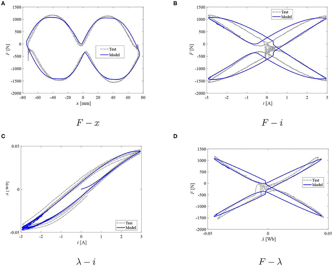
Figure 12. Damper model: measured force and reconstructed flux vs. model data; I = 3.0 A. (A) F − x. (B) F − i. (C) λ −i. (D) F − λ.
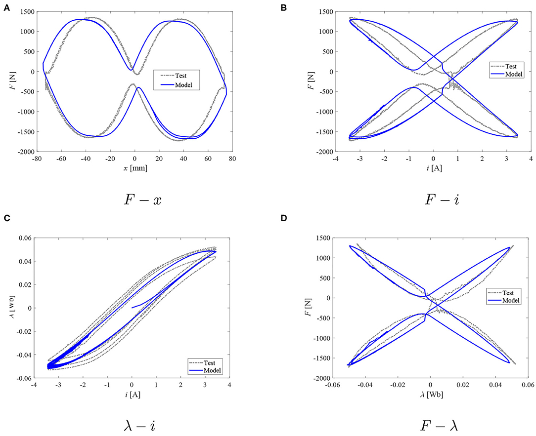
Figure 13. Damper model: measured force and reconstructed flux vs. model data; I = 3.5 A. (A) F − x. (B) F − i. (C) λ −i. (D) F − λ.
When the peak current increases from 1 to 3.5 A, on the inductor part, the parameter a was determined to decrease from the maximum value of 3 down to 1.4. On the other hand, the parameter b1 increased from 0.03 to 0.08 (3.5 A) with the increasing current. At the same time, the rate tuning parameter b2 varied from 0.7 to 0.25, and the parameter d was found to vary from 0.015 to 0.004. The time constant ζ was determined to be nearly constant – 0.015 to 0.018 s, and the off-state damping coefficient Rv = 120 Ns/m, and c = 15 s/m. The parameter R(λ) was found to be equal to 18 kN/Wb (1 A), increasing with the current up to 28.8 kN/Wb (3.5 A).
Based on the observations of plots in Figures 8–13, it seems that the evolution of damping force against the current and/or magnetic flux can be well-studied with the proposed dual hysteretic approach. At all current levels above 1 A, the model is capable of providing good quality performance in predicting both the F − x loops, the F − i relationship, as well as the F − λ plots. The force behavior at transition points as well as the hysteresis width and shape have been well-captured with the proposed approach. At the lowest current case (1 A), only the F − λ predictions are not acceptable. The flux as well as force levels are well-predicted; however, the F − λ loop's width is poorly captured, and the transition points are in the wrong quadrants of the F − λ system of coordinates which can be observed also in the F − x loop of the same figure. The model's poor prediction at the lowest peak current level is likely to be due to the above mentioned flux estimation problems.
5. Summary and Conclusions
Hysteresis has been a well-known phenomenon influencing the force/torque output of MR dampers. Prior art on this topic usually included studying the total or combined hysteresis by considering the relationship of the damping force or torque vs. displacement/velocity and current, thus ignoring the distinct nature of magnetic hysteresis and the hydraulic/mechanical hysteresis. The first one is an inherent property of ferromagnetic materials forming the damper's electromagnetic circuit. It is of a different nature to the mechanical (hydraulic) hysteresis of the devices since it does not vanish in the DC limit (as the excitation frequency approaches zero). Understanding the contribution of the two mechanisms is then vital in developing a good quality model. In MR dampers, magnetic hysteresis not only degrades any current-based control scheme performance but also reduces the actuator's dynamic range.
To distinguish between the two mechanisms, the present study extends the concept of a non-linear inductor with magnetic hysteresis (which is then linked to the damping force model). The inductor concept (based on the Duhem hysteretic operator) is employed for copying the λ − i characteristics of the solenoid. In the presented form, it simply captures the average flux variation in the structure. It requires estimating the model parameter values from the damper measurements. As such, it may be only used during a control algorithm development stage and is not suitable, for example, for damper sizing studies. The lumped parameter form may, however, be convenient for model-based control studies. Replacing the Duhem operator with the Jiles-Atherton (whose parameters are linked to magnetization characteristics features) model or the vector hysteresis modeling approach would, however, make it suitable for solving such problems at early stages of the development process, though often at the expense of higher computing cost.
The mechanical mechanisms contribution to the force output are then captured with a phenomenological Maxwell-based model of the damper featuring a spring in series with a non-linear dashpot. As demonstrated, the presented procedure allows independent interpretations of the contribution of each analyzed mechanism.
The phenomenological approach undertaken by the authors employs a posteriori models whose parameters can be computed from experimental data. Only control studies can thus be supported with it. That is in contrast with the multiphysics technique presented by Kubik and Gołdasz (2019) where the authors showed a hybrid finite-element/lumped parameter approach that can be employed at a design stage.
To further summarize and clarify, in the present study we highlighted an approach targeted toward separation of the hysteretic output of an MR flow-mode damper into two distinct hysteretic operators, namely, mechanical/hydraulic hysteresis and magnetic flux hysteresis. With the proposed approach each mechanism can be studied independently. The presented technique relies on the flux sensorless estimation technique which is particularly convenient if no access to the internal components of a damper can be gained. The damper model is phenomenological and comprises parameters that can be extracted from measurements. Moreover, it allows for the independent analyses of each hysteresis mechanisms with any existing hysteretic model. Both the Duhem model and the derived Maxwell type model were used here for illustration purposes.
Finally, application of the model in more complex transient studies requires adopting a more advanced inductor concept so that the effects of eddy currents and the hysteresis dependence on the excitation input frequency are well-captured. The advanced inductor concept is a subject of on-going study. Moreover, work on a state estimation technique based on the non-linear Kalman filter is in progress. Implementing it is crucial given the flux integration problems mentioned in the previous section.
Data Availability Statement
The raw data supporting the conclusions of this article will be made available by the authors, without undue reservation.
Author Contributions
JG conceived the model and carried out simulations. BS and ŁJ planned and carried out experiments. MK processed data, participated in model verification and contributed to the interpretation of the results. All authors provided critical feedback and helped shape the research, modeling results and manuscript.
Funding
This research had received funding from the National Agency for Academic Exchange (NAWA Poland) grant no. PPI//APM/2018/1/00027/DEC/1 and the statutory grant no. E3/611/2019/DS (Cracow University of Technology).
Conflict of Interest
JG is employed by BWI Group.
The remaining authors declare that the research was conducted in the absence of any commercial or financial relationships that could be construed as a potential conflict of interest.
References
An, J., and Kwon, D. (2003). Modeling of a magnetorheological actuator including magnetic hysteresis. J. Intell. Mater. Syst. Struct. 14, 541–550. doi: 10.1177/104538903036506
Chua, L., and Stromsmoe, K. (1970). Lumped-circuit models for nonlinear inductors exhibiting hysteresis loops. IEEE Trans. Circ. Theory 17, 564–574. doi: 10.1109/TCT.1970.1083192
Chwastek, K., and Szczygłowski, J. (2008). Estimation methods for the Jiles-Atherton model parameters-a review. Electric. Rev. 12, 145–148. Available online at: https://www.researchgate.net/profile/Krzysztof_Chwastek/publication/233991499_Estimation_methods_for_the_Jiles-Atherton_model_of_hysteresis_-_a_review/links/0fcfd50dd9c804d14f000000/Estimation-methods-for-the-Jiles-Atherton-model-of-hysteresis-a-review.pdf
Dyke, S., Spencer, B., Sain, M., and Carlson, J. (1996). Modeling and control of magnetorheological dampers for seismic response reduction. Smart Mater. Struct. 5, 565–575. doi: 10.1088/0964-1726/5/5/006
Erol, O., Gonenc, B., Senkal, D., Alkan, S., and Gurocak, H. (2012). Magnetic induction control with embedded sensor for elimination of hysteresis in magnetorheological brakes. J. Intell. Mater. Syst. Struct. 23, 427–440. doi: 10.1177/1045389X11435432
Gołdasz, J., Sapiński, B., and Jastrzębski, Ł. (2018a). Assessment of the magnetic hysteretic behaviour of MR dampers through sensorless measurements. Shock Vibrat. 2018, 1–21. doi: 10.1155/2018/3740208
Gołdasz, J., Sapiński, B., and Jastrzębski, Ł. (2018b). “On the application of Bouc-Wen hysteresis approach for modeling of MR actuators,” in ACTUATOR 2018; 16th International Conference on New Actuators (Bremen), 1–5.
Gołdasz, J., Sapiński, B., Jastrzębski, Ł., and Kubik, M. (2019). “Applicability of magnetic hysteresis model for predicting the behaviour of MR dampers,” in 9th ECCOMAS Thematic Conference on Smart Structures and Materials (Paris), 1671–1681.
Gołdasz, J., and Alexandridis, A. (2012). Medium-and high-frequency analysis of magnetorheological fluid dampers. J. Vibrat. Control 14, 2140–2148. doi: 10.1177/1077546311428637
Guo, P., Xie, J., and Guan, X. (2018). Dynamic model of MR dampers based on a hysteretic magnetic circuit. Shock Vibrat. 2018, 1–13. doi: 10.1155/2018/2784950
Jastrzębski, Ł., and Sapiński, B. (2017). Experimental investigation of an automotive magnetorheological shock absorber. Acta Mech. Automat. 11, 253–259. doi: 10.1515/ama-2017-0039
Jiles, D., and Atherton, D. (1984). Theory of ferromagnetic hysteresis. J. Appl. Phys. 55:2115. doi: 10.1063/1.333582
Jolly, M., Bender, J., and Carlson, J. (1999). Properties and applications of commercial magnetorheological fluids. J. Intell. Mater. Syst. Struct. 10, 5–13. doi: 10.1177/1045389X9901000102
Kubik, M., and Gołdasz, J. (2019). Multiphysics model of an MR damper including magnetic hysteresis. Shock Vibrat. 2019:3246915. doi: 10.1155/2019/3246915
Kubik, M., Machacek, O., Strecker, Z., Roupec, J., and Mazurek, I. (2017). Design and testing of magnetorheological valve with fast force response time and great dynamic force range. Smart Mater. Struct. 26:047002. doi: 10.1088/1361-665X/aa6066
Li, Z., Gong, Y., Li, S., and Wang, W. (2019). Magnetic hysteresis compensation control of a magnetorheological damper. Front. Mater. 6:299. doi: 10.3389/fmats.2019.00299
Macki, J., Nistri, P., and Zecca, P. (1993). Mathematical models for hysteresis. SIAM Rev. 35, 94–123. doi: 10.1137/1035005
Mayergoyz, I., Friedman, G., and Salling, C. (1989). Comparison of the classical and generalized Preisach hysteresis models with experiments. IEEE Trans. Magnet. 25, 3925–3927. doi: 10.1109/20.42479
Mayergoyz, I. D., Friedman, G., and Salling, C. (1989). Comparison of the classical and generalized Preisach hysteresis models with experiments. IEEE Trans. Magnet. 25, 3925–3927.
Mazgaj, W. (2010). Determining the Magnetic Field Distribution in Soft Magnetic Materials Incl. Hysteresis and Anisotropy. Wydawnictwo Politechniki Krakowskiej, Krakow.
Simms, N., Holmes, N., and Stanway, R. (2004). A unified modelling and model updating procedure for electrorheological and magnetorheological dampers. Smart Mater. Struct. 13, 100–121. doi: 10.1088/0964-1726/13/1/012
Szczygłowski, J. (2001). Influence of eddy currents on magnetic hysteresis loops in soft magnetic materials. J. Magnet. Magnet. Mater. 223, 97–102. doi: 10.1016/S0304-8853(00)00584-9
Wang, D., and Liao, W. (2011). Magnetorheological fluid dampers: a review of parametric modelling. Smart Mater. Struct. 20:023001. doi: 10.1088/0964-1726/20/2/023001
Keywords: MR damper, hysteretic behavior, magnetic hysteresis, inductor model, hysteresis
Citation: Gołdasz J, Sapiński B, Jastrzębski Ł and Kubik M (2020) Dual Hysteresis Model of MR Dampers. Front. Mater. 7:236. doi: 10.3389/fmats.2020.00236
Received: 16 April 2020; Accepted: 29 June 2020;
Published: 06 October 2020.
Edited by:
Weihua Li, University of Wollongong, AustraliaReviewed by:
Xianzhou Zhang, Independent Researcher, Tomago, AustraliaLuwei Zhou, Fudan University, China
Copyright © 2020 Gołdasz, Sapiński, Jastrzębski and Kubik. This is an open-access article distributed under the terms of the Creative Commons Attribution License (CC BY). The use, distribution or reproduction in other forums is permitted, provided the original author(s) and the copyright owner(s) are credited and that the original publication in this journal is cited, in accordance with accepted academic practice. No use, distribution or reproduction is permitted which does not comply with these terms.
*Correspondence: Janusz Gołdasz, amdvbGRhc3pAcGsuZWR1LnBs