 Ada Amendola
 Antonino Favata
 Andrea Micheletti
- 1Department of Civil Engineering, University of Salerno, Fisciano, Italy
- 2Department of Structural and Geotechnical Engineering, Sapienza University of Rome, Rome, Italy
- 3Department of Civil Engineering and Computer Science Engineering, University of Rome Tor Vergata, Rome, Italy
A physical model of a tensegrity columns is additively manufactured in a titanium alloy. After removing sacrificial supports, such a model is post-tensioned through suitable insertion of Spectra® cables. The wave dynamics of the examined system is first experimentally investigated by recording the motion through high-speed cameras assisted by a digital image correlation algorithm, which returns time-histories of the axial displacements of the bases of each prism of the column. Next, the experimental response is mechanically simulated by means of two different models: a stick-and-spring model accounting for the presence of bending-stiff connections between the 3D-printed elements (mixed bending-stretching response), and a tensegrity model accounting for a purely stretching response. The comparison of theory and experiment reveals that the presence of bending-stiff connections weakens the nonlinearity of the wave dynamics of the system. A stretching-dominated response instead supports highly compact solitary waves in the presence of small prestress and negligible bending stiffness of connections.
1. Introduction
The dynamics of acoustic metamaterials has been intensively investigated over recent years, with the aim of designing unconventional mechanical devices like acoustic band gap materials, shock protectors, acoustic lenses, and energy trapping containers, to name just a few examples (refer, e.g., to Lu et al., 2009; Craster and Guenneau, 2013; Theocharis et al., 2013; Hussein et al., 2014; Leonard et al., 2014; Chronopoulos et al., 2017; Claeys et al., 2017; Harne et al., 2017; Ponge et al., 2017; Tallarico et al., 2017; Miniaci et al., 2018 and references therein). It has been shown that engineered metamaterials may find application for protecting materials and structures against impacts with external objects (Fraternali et al., 2010; Mitchell et al., 2014), as well as for the design of sound-focusing devices (Spadoni and Daraio, 2010), the manufacturing of noninvasive sensors and actuators for structural health monitoring (Ngo et al., 2012; Rizzo et al., 2014), and the fabrication of novel seismic protection devices (Brûlé et al., 2014; Krö¨del et al., 2015; Miniaci et al., 2016; Colombi et al., 2017; La Salandra et al., 2017).
Lattice structures obtained by assembling tensegrity units, such as T3 tensegrity prisms (Skelton and de Oliveira, 2010), exhibit a mechanical response that can be continuously varied from hardening to softening, by changing the geometrical, mechanical, and prestress parameters (Fraternali et al., 2012, 2014a,b; Amendola et al., 2014, 2015; Rimoli, 2016; Montuori and Skelton, 2017; Rimoli and Pal, 2017). The geometrically nonlinear response of a tensegrity system is caused by the presence of one or more infinitesimal mechanisms, i.e., sets of nodal displacements causing second-order member elongations, owing to the fact that the equilibrium operator is singular in the considered configuration (Calladine, 1978; Calladine and Pellegrino, 1991; Micheletti, 2012; Fraternali et al., 2015; Modano et al., 2018). Recent studies (Fraternali et al., 2012, 2014b) have revealed that tensegrity columns composed of T3 prisms are suitable for use as acoustic lenses supporting extremely compact solitary waves.
In this work, we experimentally test the dynamic response of a tensegrity column subjected to impact loading, and correspondingly we perform numerical simulations of the examined tests using two different elastic models, respectively described in Favata et al. (2014) and Davini et al. (2016). An additive manufacturing (AM) technique based on Electron Beam Melting (EBM) is employed to build all the elements of the tested structure, except for the cables, which are subsequently added to the 3d-printed structure through a post-tensioning technique (Amendola et al., 2015). The mechanical modeling of such a structure is first analyzed through the stick-and-spring model presented in Favata et al. (2014), which takes into account that the nodes of the 3D-printed structure form bending-stiff connections. It models the system by considering bars and bases to be inflexible, by describing the cables as linear springs, and attaching angular springs to the nodes (mixed bending-stretching response). The second examined model (Davini et al., 2016) is instead a pure tensegrity model that introduces frictionless pin-connections between elements, describes the cables as linear springs, and models the bars and the bases of the prisms as rigid bodies (purely stretching response). Other than comparing for the first time the experimental impact response of a tensegrity column to the numerically predicted response of the above models, this work highlights differences and similarities between such models, providing useful directions for the design of tensegrity metamaterials with sound-focusing abilities.
2. Experimental Setup
We experimentally investigate the dynamic response of a 3D-printed physical model of a tensegrity column (Amendola et al., 2015) under impact loading. Such structure consists of ten regular tensegrity prisms with triangular bases (T3 prisms) (Skelton and de Oliveira, 2010) superposed to each other. Figure 1A shows the tested column partly manufactured in Ti6Al4V titanium alloy using the EBM technique (Amendola et al., 2015) and the computer-aided design (CAD) model drawn in Figure 1B. The Arcam S12 EBM facility at the Department of Materials Science and Engineering, University of Sheffield was employed to manufacture the examined structure, by depositing layers of Ti6Al4V powder with minimum feature size down to 0.4 mm (Tammas-Williams et al., 2015).
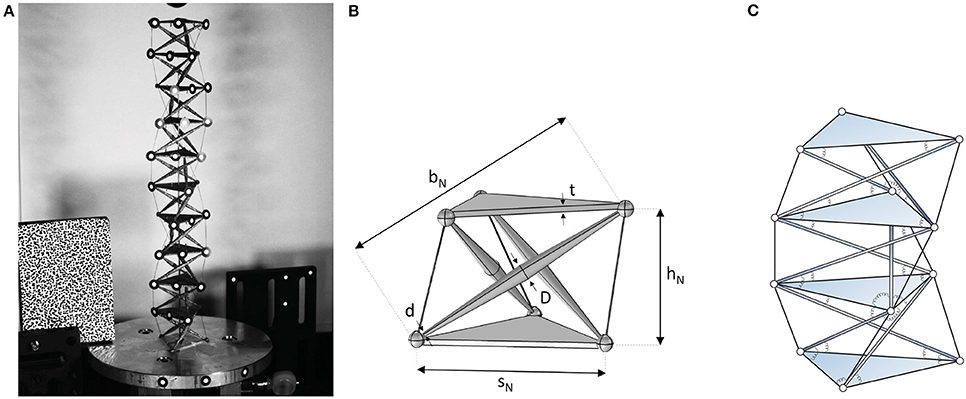
Figure 1. The tensegrity column under test (A), CAD model of a single prism (B), and sketch of a portion of the model showing also the angular springs associated to the wedges of the S&S structure (C).
Each T3 prism of the column is left-handed, i.e., the upper base is rotated counter-clockwise with respect to the bottom base by an angle of 5π/6 about the prism's axis1 (cf. Davini et al., 2016). Each T3 prism is made by three bi-conical bars connected to the vertices of two triangular plates with thickness t through spherical nodes with 3 mm diameter. These elements are 3D-printed together with the aid of additional sacrificial linear elements which are mechanically removed afterward. Three strings elements (or cables) made of Spectra® fibers are then added to each prism on using the post-tension technique illustrated in Amendola et al. (2015). The geometric properties of a prism are given in Table 1. The symbols sN, bN, and hN denote respectively the length of the edges of the base plates, the length of the bars, and the height of the prism (measured as the distance between the base centers) (Amendola et al., 2015) (cf. Figure 1B). The maximum and minimum diameters of the bars are denoted by D and d, respectively.
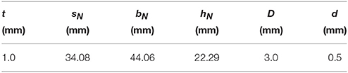
Table 1. Geometrical properties of a T3 prism.
An in-house experimental setup is designed and assembled to apply an impact load to the top base of the column, while keeping the bottom base fixed to an aluminium plate. The strings of the structure are pre-stretched by passing them through bridge pins applied to the aluminum plate (Figure 1A). A vertical thin rod passing through the units was inserted in order to stabilize the column and prevent possible bending modes.
The top base of the columns is impacted by a spherical striker with 5 g mass made of Polytetrafluoroethylene (PTFE) (Figure 1A), which falls with null initial velocity for 0.5 m in a duct delimited by four Teflon tubes. The motion of the column produced by the impact with the striker is recorder through two high-speed cameras FASTCAM Mini UX100, and the axial (vertical) displacements of the upper base of each unit are measured using a Digital Image Correlation technique (Deng et al., 2017; Schaeffer et al., 2017). Such a technique employs image acquistion with a rate of 4,000 fps at 1,280 × 1,024 pixel resolution, and the triggering of the striker downfall through a precision screw, in order to obtain a repeatable perturbation of the impacted base (Nadkarni et al., 2016).
3. Stick-and-Spring Model
The EBM technique described in section 2 does not allow for the realization of spherical hinges between bars and base plates of the tensegrity column; on the contrary, the nodes of the 3D-printed structure provide bending-stiff connections between such elements. This observation leads us to employ a stick-and-spring (S&S) model (Favata et al., 2014) to describe the dynamic response of the physical model under examination.
A S&S structure is a collection of nodes, edges, and wedges: edges are imagined as node-to-node inflexible but extensible straight sticks, acting as axial springs when extended; wedges are imagined as complexes of two sticks sharing one end node, equipped by an angular spring reacting to relative rotations of the two wedge sticks in their common plane. A S&S structure differs from a tensegrity structure because, owing to the presence of angular springs, edges are subjected to shear forces and bending moments, in addition to axial forces (see Figure 1C).
3.1. Model Description
The combinatorial description of a S&S structure is given by the triplet consisting of: (i) a collection of points, called nodes, of the three-dimensional Euclidean space; (ii) a collection of edges, that is, two-elements subsets of ; (iii) a collection of wedges, that is, three-elements subsets of . We say that is the edge connecting nodes , and that , with , is the wedge with head node i and tail nodes j and k. We denote by pi the referential position vector of the typical node i with respect to a chosen origin point, by ui its displacement, and by qi : = pi + ui its current position vector.
We denote the change in length of edge ij, with , and the change in angle of wedge ijk, with by δℓij and δθijk, respectively. The corresponding linearized length variations are:
where u is the string of nodal-displacement vectors, [u] = […,ui, …], while bij, bijk are vectors depending on referential nodal positions pi, (see Favata et al., 2014 for details). On denoting by η the string of strain components, [η] = […, δℓij, …|…, δθijk, …], relations (1) can be given the following compact form:
where the linear mapping B is the kinematic compatibility operator. We denote by f and χ respectively the string of nodal-force vectors and the string of stress measures conjugated with η. With this notation, the balance equations can be written as:
where A = BT is the equilibrium operator.
Next, let the (positive) spring constants κij and λijk characterize the linear elastic response of edge and wedge springs, respectively, so that the elastic energy stored in a S&S structure can be written as:
with ℓij and the current length and the rest length of the axial spring on edge ij, while θijk and are the current angle and the rest angle of the angular spring on wedge ijk. On introducing the kinetic energy:
with M a diagonal mass operator corresponding to lumped nodal masses, the nonlinear motion equations are given by:
where is the equilibrium operator in the current placement. This equation can be linearized about an equilibrium placement q0, obtaining:
where is the tangent stiffness operator2.
The response of the tensegrity column under impact loading is obtained through numerical integration of (6) and (7) subject to assigned initial conditions.
3.2. Simulation of Impact Tests
The impact test was simulated by means of the S&S model under the following assumptions.
• Cables are modeled as edges, with stiffness , where Ec is the Young modulus, dc the diameter, and is the current length of the cables, with lb the length of the bar and a the base radius;
• Cable prestress is considered to be negligible3;
• Bars are modeled as edges with stiffness , where Eb is the Young modulus and db the diameter;
• Each triangular base is modeled as three pin-jointed bars of stiffness κb forming the triangle;
• Wedges are considered between base triangles and bars (see Figure 1B, right), their stiffness is , with α a dimensionless parameter measuring the relative importance of edge-stretching and wedge-opening (Favata et al., 2014), which in the present study is fitted with the experimental results;
• Nodal masses m are assigned by subdividing the total measured mass of the structure, 53.0 g into 3 (vertices) × 10 (bases) = 30 equal parts.
• As initial value of the downward velocity we assumed v0 = 2 m/s, by averaging measurements during a short time interval after impact. We also assumed that the impact cause the top base to have an initial angular velocity about the prism's axis given by rad/s, with , so that the top base initially moves along the infinitesimal mechanism of the top prism (Fraternali et al., 2014a).
Table 2 summarizes the adopted values of the S&S modeling parameters.

Table 2. Model parameters.
The stiffness of wedge springs, controlled by the dimensionless parameter α, is assigned by matching the time at which the top base returns to the initial position (subsequently continuing its upward motion). In the experiment, ms; in the simulation, the same value is found when α = 6.0655 · 10−4. We observe a good agreement between oscillation amplitudes in the two cases.
Figure 2 shows a comparison on the displacements of the prisms #2, #4, #6, #8, #10 (top prism), between experimental results (dotted line) and numerical results (solid line). Numerical results are obtained by integrating the nonlinear equation of motion (6). Figure 3A shows a comparison on the displacements of the first and the last prism, between experimental results (dotted line), results obtained by numerical integration of both the nonlinear equation of motion (6) (solid line), and those obtained from the linearized equation of motion (6) (dashed line). Figure 3B shows numerical results for the axial strain of the first and last prism, which is defined as the relative displacement between the two bases of a prism, divided by hN. Experimental results display larger oscillations, in particular for the top prism. In this regard, we observed that in the experiment triangular bases do not remain perfectly horizontal during the motion, and this is likely to be the reason of the larger oscillations in the measured displacement. The first maximum value of the displacement umax and the correspondent time tmax is reported in Table 3. It is worth noting that, by looking at Table 3 and Figure 2, the response in the linearized case is close to that in the nonlinear case.
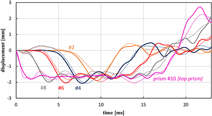
Figure 2. Base displacements obtained from experiments (dotted line) and numerical simulations with nonlinear theory (solid line) of the S&S model.
Figure 3. (A) Displacements of the top and bottom base, comparison between experiments (dotted line) and numerical simulations with nonlinear theory (solid line) and linearized theory (dashed line) of the S&S model. (B) Axial strains in the top and bottom prism obtained with nonlinear theory (solid line) and linearized theory (dashed line).
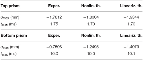
Table 3. First maximum value of the displacement umax and correspondent time tmax.
4. Pure Tensegrity Model
Both simulations and experimental results presented in the previous section show that the mixed bending-stretching regime produces a not localized wave transmission response of the tensegrity column under examination. In this section, we propose some possible directions toward the design of a device with more “focused” dynamic response under impact loading in the pure stretching regime. In order to do this, we adopt the simpler, pure tensegrity model presented in Davini et al. (2016), where the Lagrange's equation of motion of a tensegrity column are solved numerically. The assumptions of this model are the following ones: only cyclic-symmetric motions with respect to the column's axis are considered; nodes are frictionless hinges between connected elements; all bars are rigid and massless; cables are linearly elastic and massless. In our case, each triangular base is a rigid body with a mass 3m and moment of inertia 3ma2.
We investigated the following three cases.
CASE 1 — We considered cable stiffness to be the same as in the present S&S model. Then we determined the cable prestrain by matching the time at which the top base returns to the initial position with that measured during the experiment. By doing so, the resulting prestrain takes the unrealistic value of 85%. The results are shown in Figure 4 (dashed line), where it is possible to see a linear behavior similar to that of the mixed bending-stretching response.
CASE 2 — We assign the more realistic value of 5% to the prestrain and determine the cable stiffness by matching the time with that of the experiment. The resulting cable stiffness is 15.5 times higher than that of the original structure. Results are shown in Figure 4 (dash-dot line), where we still observe a response similar to that of the mixed bending-stretching regime.
CASE 3 — We assign a low prestrain to cables, equal to 1% and, again by matching the time with that of the experiment, we determine the stiffness of cables to be 55.5 times higher than that of the original structure. The results are shown in Figure 4 (solid line), which displays a much more marked nonlinear response4.
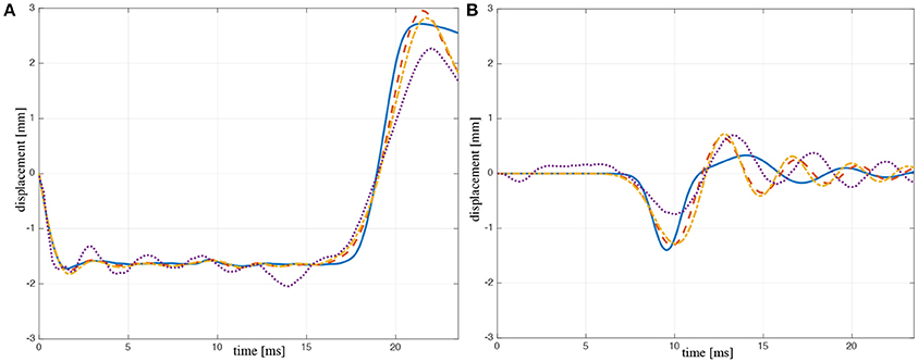
Figure 4. Displacements of top prism (A) and bottom prism (B): experiments (dotted line), Case 1 (dash-dot line), Case 2 (dashed line), and Case 3 (solid line) of the pure tensegrity model.
It is worth noting that the above cases refer to models of tensegrity columns different from that experimentally tested in the present work (experimental model), and they are here presented with the aim of exploring the nonlinear potential of the wave dynamics of pure tensegrity lattices. The results in Figure 4 show that the tensegrity models of Cases 1 and 2 reproduce fairly well the displacement vs. time response of the experimental model, while there are larger differences with Case 3.
For a better visualization of nonlinear effects, we repeated the simulations on a column composed of 100 units, and we represented in Figure 5 the strain of each prism of the column at a fixed time (t = 65 ms). In all the results shown in Figure 5 we observe the formation of a leading compression strain pulse followed by an oscillatory tail. By comparing Cases 1–3 and the Stick-and-Spring model analyzed in Sect. 3 (nonlinear theory), we observe that for Case 3 (when the cross-cable prestrain is 1%) the deformation of the column is more localized at the wave front, since in this case the amplitude of the leading compression strain pulse is much larger than that of the oscillatory tail, and is more markedly separated from the tail (Figure 5D), as compared to Cases 1–2 (Figures 5B,C) and the Stick-and-Spring model (Figure 5A).
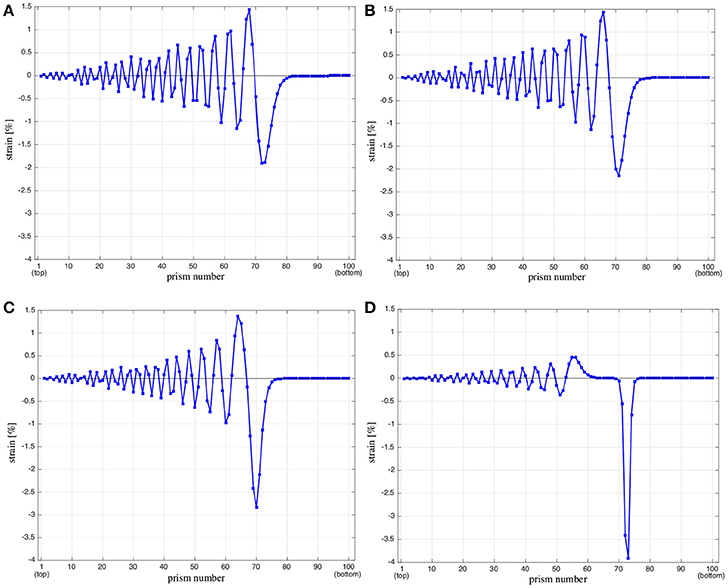
Figure 5. Snapshot at 65 ms of prism strains along a column composed by 100 prisms. Nonlinear Stick-and-Spring model (A). Pure tensegrity model: Case 1 (B); Case 2 (C), and Case 3 (D).
5. Conclusion and Future Work
5.1. Concluding Remarks
We have performed an impulsive dynamic test on a physical model of a tensegrity column, on comparing the measured displacements to those computed numerically through two different models: a stick-and spring model accounting for bending deformation of the nodes (Favata et al., 2014), and a pure tensegrity model accounting for a pure-stretching response of all the members of the system (Davini et al., 2016). The first model is intended to capture the experimental response of the analyzed physical model, while the second one is aimed at providing directions for the design of alternative systems featuring highly nonlinear dynamic response. The given results show a fairly good agreement between measurements and simulations performed with the first model. The second model is also able to reproduce the response observed during the experiment when one prescribes a suitable prestrain to the cables, since such a property significantly influences the axial stiffness of the units (Fraternali et al., 2014a). We have observed that bending-stiff nodal connections, a feature of the 3D-printed structure due to the not-negligible size of the junctions, may greatly reduce nonlinearities in the response of tensegrity lattices. We found that a similar effect can also be obtained in the second model by fictitiously raising the prestress level. This behavior can be explained by considering that the tangent stiffness of the tensegrity lattice is the sum of a material contribution (owing mainly to the stiffness of angular springs) and a geometric contribution (owing to prestress) (Favata et al., 2014). In relation to this, we observed also that a more marked nonlinear behavior occurs for smaller prestress levels and smaller values of the stiffness of angular springs.
5.2. Future Work
The results of the present study highlight that a pure tensegrity behavior with negligible bending deformation of the nodes and low prestress may lead to design novel metamaterials that enable unconventional wavefocusing methodologies based on the propagation of localized stress/strain waves, whose support is concentrated in narrow regions of space. This obviously calls for the adoption of manufacturing techniques that are able to build perfect hinges at the nodes, such as e.g. the multiscale AM techniques described in Meza et al. (2014); Zheng et al. (2014). Arrays of tensegrity columns with stretching-dominated response may be employed to fabricate tunable focus acoustic lenses whose working principle is based on the propagation of localized stress waves, whose support can be adjusted through the control of the global precompression of the structure, and/or the prestretch of the cables forming the units. On applying different levels of prestress to such metamaterials, one can be able to generate compact stress waves with different phases within the system, which are expected to interact at a focal point in an adjacent medium (i.e., a material defect to be targeted) (Spadoni and Daraio, 2010). We address specific studies on such engineering applications of tensegrity lattices to future work, with the aim of designing and manufacturing novel acoustic lenses, and innovative sensors/actuators for monitoring structural health and damage detection in materials and structures (Rizzo et al., 2014).
Author Contributions
AA run the experiments at the Department of Mechanical and Process Engineering, ETH Zurich, on occasion of an internship under the supervision of Prof. Chiara Daraio. AM led the formulation and implementation of the tensegrity model and contributed to the formulation of the stick-and-spring model. AF led the formulation and implementation of the stick-and-spring model and contributed to the formulation of the tensegrity model. All the authors collaborated on the writing of the manuscript.
Conflict of Interest Statement
The authors declare that the research was conducted in the absence of any commercial or financial relationships that could be construed as a potential conflict of interest.
Acknowledgments
The authors wish to thank Evert Hernández-Nava, Christopher Smith, Russell Goodall, and Ian Smith for their support and advice during the manufacturing of the Ti-6Al-4V models at the Department of Materials Science and Engineering, University of Sheffield, UK. The authors are also grateful to Chiara Daraio for providing continuous support and advice during the experimental tests, which were run at the Department of Mechanical and Process Engineering of ETH Zurich. AF acknowledges the financial support of Sapienza University of Rome (University Grants 2016 and 2017).
Footnotes
1. ^When a T3 prism is right-handed the base is rotated clockwise by the same angle.
2. ^See Favata et al. (2014) for a detailed expression of kT.
3. ^We checked that, owing to the small axial stiffness of cables, a modest prestress does not change results significantly.
4. ^This is highlighted for example by the different amplitudes in tension and compression of the bottom prism (Figure 4B, solid line), owing to a stiffer response in tension.
References
Amendola, A., Carpentieri, G., De Oliveira, M., Skelton, R. E., and Fraternali, F. (2014). Experimental investigation of the softening-stiffening response of tensegrity prisms under compressive loading. Compos. Struct. 117, 234–243. doi: 10.1016/j.compstruct.2014.06.022
Amendola, A., Hernández-Nava, E., Goodall, R., Todd, I., Skelton, R. E., and Fraternali, F. (2015). On the additive manufacturing, post-tensioning and testing of bi-material tensegrity structures. Compos. Struct. 131, 66–71. doi: 10.1016/j.compstruct.2015.04.038
Brûlé, S., Javelaud, E. H., Enoch, S., and Guenneau, S. (2014). Experiments on seismic metamaterials: molding surface waves. Phys. Rev. Lett. 112, 1–5. doi: 10.1103/PhysRevLett.112.133901
Calladine, C. R., and Pellegrino, S. (1991). First-order infinitesimal mechanisms. Int. J. Solids Struct. 27, 505–515.
Calladine, C. R. (1978). Buckminster Fuller's ‘tensegrity’ structures and Clerk Maxwell's rules for the construction of stiff frames. Int. J. Solids Struct. 14, 161–172.
Chronopoulos, D., Antoniadis, I., and Ampatzidis, T. (2017). Enhanced acoustic insulation properties of composite metamaterials having embedded negative stiffness inclusions. Extreme Mech. Lett. 12, 48–54. doi: 10.1016/j.eml.2016.10.012
Claeys, C., Rocha de Melo Filho, N. G., Van Belle, L., Deckers, E., and Desmet, W. (2017). Design and validation of metamaterials for multiple structural stop bands in waveguides. Extreme Mech. Lett. 12, 7–22. doi: 10.1016/j.eml.2016.08.005
Colombi, A., Craster, R. V., Colquitt, D., Achaoui, Y., Guenneau, S., Roux, P., and Rupin, M. (2017). Elastic wave control beyond band-gaps: shaping the flow of waves in plates and half-spaces with subwavelength resonant rods. Front. Mater. 3:10. doi: 10.3389/fmech.2017.00010
Craster, R. V., and Guenneau, S. (2013). Acoustic Metamaterials, Negative Refraction, Imaging, Lensing and Cloaking. Springer Netherlands.
Davini, C., Micheletti, A., and Podio-Guidugli, P. (2016). On the impulsive dynamics of T3 tensegrity chains. Meccanica 51, 2763–2776. doi: 10.1007/s11012-016-0495-y
Deng, B., Raney, J. R., Tournat, V., and Bertoldi, K. (2017). Elastic vector solitons in soft architected materials. Phys. Rev. Lett. 118:204102. doi: 10.1103/PhysRevLett.118.204102
Favata, A., Micheletti, A., and Podio-Guidugli, P. (2014). A nonlinear theory of prestressed elastic stick-and-spring structures. Int. J. Eng. Sci. 80, 4–20. doi: 10.1016/j.ijengsci.2014.02.018
Fraternali, F., Carpentieri, G., and Amendola, A. (2014a). On the mechanical modeling of the extreme softening/stiffening response of axially loaded tensegrity prisms. J. Mech. Phys. Solids 74, 136–157. doi: 10.1016/j.jmps.2014.10.010
Fraternali, F., Carpentieri, G., Amendola, A., Skelton, R. E., and Nesterenko, V. F. (2014b). Multiscale tunability of solitary wave dynamics in tensegrity metamaterials. Appl. Phys. Lett. 105:201903. doi: 10.1063/1.4902071
Fraternali, F., De Chiara, E., and Skelton, R. E. (2015). On the use of tensegrity structures for kinetic solar facades of smart buildings. Smart Mater. Struct. 24:105032. doi: 10.1088/0964-1726/24/10/105032
Fraternali, F., Porter, M. A., and Daraio, C. (2010). Optimal design of composite granular protectors. Mech. Adv. Mat. Struct. 17, 1–19. doi: 10.1080/15376490802710779
Fraternali, F., Senatore, L., and Daraio, C. (2012). Solitary waves on tensegrity lattices. J.Mech. Phys. Solids 60, 1137–1144. doi: 10.1016/j.jmps.2012.02.007
Harne, R. L., Song, Y., and Dai, Q. (2017). Trapping and attenuating broadband vibroacoustic energy with hyperdamping metamaterials. Extreme Mech. Lett. 12, 41–47. doi: 10.1016/j.eml.2016.05.017
Hussein, M. I., Leamy, M. J., and Ruzzene, M. (2014). Dynamics of phononic materials and structures: historical origins, recent progress, and future outlook. Appl. Mech. Rev. 66, 1–38. doi: 10.1115/1.4026911
Krö¨del, S., Thomé, N., and Daraio, C. (2015). Wide band-gap seismic metastructures. Extreme Mech. Lett. 4, 111–117. doi: 10.1016/j.eml.2015.05.004
La Salandra, V., Wenzel, M., Bursi, O. S., Carta, G., and Movchan, A. B. (2017). Conception of a 3D metamaterial-based foundation for static and seismic protection of fuel storage tanks. Front. Mater. 4:30. doi: 10.3389/fmats.2017.00030
Leonard, A., Ponson, L., and Daraio, C. (2014). Exponential stress mitigation in structured granular composites. Extreme Mech. Lett. 1, 23–28. doi: 10.1016/j.eml.2014.12.005
Lu, M. H., Feng, L., and Chen, Y. F. (2009). Phononic crystals and acoustic metamaterials. Mater. Today 12, 34–42. doi: 10.1016/S1369-7021(09)70315-3
Meza, L. R., Das, S., and Greer, J. R. (2014). Strong, lightweight, and recoverable three-dimensional ceramic nanolattices. Science 345, 1322–1326. doi: 10.1126/science.1255908
Micheletti, A. (2012). Bistable regimes in an elastic tensegrity system. Proc. R. Soc. 469:30052. doi: 10.1098/rspa.2013.0052
Miniaci, M., Krushynska, A., Bosia, F., and Pugno, N. M. (2016). Large scale mechanical metamaterials as seismic shields. New J. Phys. 18, 1–16. doi: 10.1088/1367-2630/18/8/083041
Miniaci, M., Mazzotti, M., Radzieński, M., Kherraz, N., Kudela, P., Ostachowicz, W., et al. (2018). Experimental observation of a large low-frequency band gap in a polymer waveguide. Front. Mater. 5:8. doi: 10.3389/fmats.2018.00008
Mitchell, S. J., Pandolfi, A., and Ortiz, M. (2014). Metaconcrete: designed aggregates to enhance dynamic performance. J. Mech. Phys. Solids 65, 69–81. doi: 10.1016/j.jmps.2014.01.003
Modano, M., Mascolo, I., Fraternali, F., and Bieniek, Z. (2018). Numerical and analytical approaches to the self-equilibrium problem of class θ = 1 tensegrity metamaterials. Front. Mater. 5:5. doi: 10.3389/fmats.2018.00005
Montuori, R., and Skelton, R. E. (2017). Globally stable tensegrity compressive structures for arbitrary complexity. Compos. Struct. 179, 682–694. doi: 10.1016/j.compstruct.2017.07.089
Nadkarni, N., Arrieta, A. F., Chong, C., Kochmann, D. M., and Daraio, C. (2016). Unidirectional transition waves in bistable lattices. Phys. Rev. Lett. 116:244501. doi: 10.1103/PhysRevLett.116.244501
Ngo, D., Fraternali, F., and Daraio, C. (2012). Highly nonlinear solitary wave propagation in Y-shaped granular crystals with variable branch angles. Phys. Rev. E 85:036602. doi: 10.1103/PhysRevE.85.036602
Ponge, M. F., Poncelet, O., and Torrent, D. (2017). Dynamic homogenization theory for nonlocal acoustic metamaterials. Extreme Mech. Lett. 12, 71–76. doi: 10.1016/j.eml.2016.10.006
Rimoli, J. J., and Pal, R. K. (2017). Mechanical response of 3-dimensional tensegrity lattices. Compos. Part B 115, 30–42. doi: 10.1016/j.compositesb.2016.10.046
Rimoli, J. J. (2016). “On the impact tolerance of tensegrity-based planetary landers,” in 57th AIAA/ASCE/AHS/ASC Structures, Structural Dynamics, and Materials Conference (San Diego, CA), 1511.
Rizzo, P., Ni, X., Nassiri, S., and Vandenbossche, J. (2014). A solitary wave-based sensor to monitor the setting of fresh concrete. Sensors 14, 12568–12584. doi: 10.3390/s140712568
Schaeffer, M., Trainiti, G., and Ruzzene, M. (2017). Optical measurement of in-plane waves in mechanical metamaterials through digital image correlation. Sci. Rep. 7:42437. doi: 10.1038/srep42437
Spadoni, A., and Daraio, C. (2010). Generation and control of sound bullets with a nonlinear acoustic lens. Proc. Natl. Acad. Sci. U.S.A. 107, 7230–7234. doi: 10.1073/pnas.1001514107
Tallarico, D., Trevisan, A., Movchan, N. V., and Movchan, A. B. (2017). Edge waves and localization in lattices containing tilted resonators. Front. Mater. 4:16. doi: 10.3389/fmats.2017.00016
Tammas-Williams, S., Zhao, H., Leonard, F., Derguti, F., Todd, I., and Prangnell, P. B. (2015). XCT analysis of the influence of melt strategies on defect population in Ti6Al4V components manufactured by selective electron beam melting. Mater. Charact. 102, 47–61. doi: 10.1016/j.matchar.2015.02.008
Theocharis, G., Boechler, N., and Daraio, C. (2013). “Nonlinear phononic structures and metamaterials,” in Acoustic Matematerials and Phononic Crystals, Springer Series in Solid State Sciences, ed P. A. Deymier (Berlin: Springer), 173.
Keywords: tensegrity columns, wave dynamics, additive manufacturing, experimental testing, stick-and-spring structure, solitary waves
Citation: Amendola A, Favata A and Micheletti A (2018) On the Mechanical Modeling of Tensegrity Columns Subject to Impact Loading. Front. Mater. 5:22. doi: 10.3389/fmats.2018.00022
Received: 16 February 2018; Accepted: 28 March 2018;
Published: 17 April 2018.
Edited by:
Alberto Corigliano, Politecnico di Milano, ItalyReviewed by:
Marco Miniaci, Georgia Institute of Technology, United StatesMassimiliano Gei, Cardiff University, United Kingdom
Copyright © 2018 Amendola, Favata and Micheletti. This is an open-access article distributed under the terms of the Creative Commons Attribution License (CC BY). The use, distribution or reproduction in other forums is permitted, provided the original author(s) and the copyright owner are credited and that the original publication in this journal is cited, in accordance with accepted academic practice. No use, distribution or reproduction is permitted which does not comply with these terms.
*Correspondence: Ada Amendola, YWRhYW1lbmRvbGExQHVuaXNhLml0