 Chenxiang Liu
 Masoud Hemmatian
 Ramin Sedaghati
 Guilin Wen2
- 1Department of Mechanical, Industrial and Aerospace Engineering, Concordia University, Montreal, QC, Canada
- 2School of Mechanical and Electrical Engineering, Guangzhou University, Guangzhou, China
The present study aims at the development of a magnetorheological elastomer (MRE) based semi-active seat suspension isolator and its adaptive control using a neural network (NN) control scheme. Isotropic MRE samples with 25% volume fraction of iron particles have been fabricated and then characterized under shear mode using a rotary magneto-rheometer to obtain MRE's viscoelastic properties (shear storage and loss moduli) under different levels of applied magnetic flux density. Results reveal a significant change in the storage and loss moduli with respect to the varied magnetic field. The viscoelastic properties of the MRE are then utilized to design an MRE-based seat suspension isolator in order to attenuate the transmitted vibration to the driver. For this purpose, the modeling of the seat incorporated with the MRE-based isolator is derived and subsequently, a novel NN control scheme is proposed for the semi-active control of the MRE-based isolator. The convergence and stability of the proposed control strategy have been mathematically verified using the Lyapunov method. Finally, the performance of the proposed control strategy is compared with those obtained using passive and widely used sky-hook controllers under different types of excitation including harmonic motion, road bump, and random profile. It is shown that the proposed NN controller considerably mitigates the vibration of the driver seat and outperforms the passive and skyhook controllers over the frequency range of interest.
Introduction
Long-term exposure to the low frequency and large amplitude vibrations from car seats can lead to severe adverse health effects on the drivers (Wilder et al., 1994). Seat suspension isolators play a critical role in the improvement of ride comfort and mitigation of whole-body vibration transmitted to the driver (Choi et al., 2001). Generally, the seat suspension isolator systems are categorized as passive, active, or semi-active systems (Symans and Constantinou, 1999). The seat suspension systems incorporating a passive control scheme are mainly effective for a narrow high-frequency range, which has been defined at early stages of design (Deng and Gong, 2008). While active isolators demonstrate a considerably better performance compared to the passive systems, their practical applications are limited mainly due to their complex control hardware, high energy consumption, and potential instability (Yang et al., 2014). Considering this, the semi-active seat suspension systems, which have the fail-safe features of passive systems and adaptability of active systems, have received considerable attention (Du et al., 2011; Nguyen et al., 2015).
Semi-active isolators featuring smart magnetorheological (MR) materials can effectively utilize the adjustable viscoelastic properties to develop the required control forces. This unique adaptability feature combined with their inherent fail-safe design and low power requirements makes MR-based isolators attractive adaptive devices which can attenuate transmitted vibrations in a wide range of applications. Magnetorheological elastomers (MREs) are solid analogs of MR fluids which can provide both variable stiffness and damping under varying applied magnetic fields. This unique feature can be effectively utilized for the development of novel and practical semi-active isolators. MREs consist of micron-sized ferromagnetic particles dispersed into an elastomeric medium. Thus, they do not encounter the limitations often posed by MR fluids, such as sedimentation and leakage (Li et al., 2014). Upon application of an external magnetic field, the magnetic particles attempt to align themselves along the magnetic field line, which results in an instant change in MRE's viscoelastic properties.
While substantial efforts have been made on the development, characterization, modeling, and design of MRE-based devices (Kallio et al., 2007; Fu et al., 2016a; Nguyen et al., 2018; Dargahi et al., 2019a,b), very limited studies have focused on the design of controllers for MRE-based vibration isolation systems. The strong non-linearity of MRE-based isolation systems and the constraint of the applied magnetic density make controller design highly complicated. In this subject, an ON-OFF or sky-hook control strategy is the most widely used control strategy for the vibration attenuation of MRE-based devices, due to its robustness, simple control law design, and effectiveness in resonance alleviation (Liao et al., 2012). However, the control performance of the ON-OFF control is limited mainly due to the fact that only two control input states (ON- and OFF-state) can be performed. Fuzzy logic controller, in which the control law is designed by taking advantage of the expert knowledge, was also proposed for the MRE-based vibration isolation devices (Fu et al., 2016a; Nguyen et al., 2018; Gu et al., 2019). The merit of the fuzzy controller is that it does not require complicated mathematical modeling. However, its effectiveness relies highly on the preset fuzzy rules based on expert knowledge. The clipped-optimal and Lyapunov-based controllers were also proposed for MRE-based vibration isolation devices (Opie and Yim, 2009; Du et al., 2011; Behrooz et al., 2014). However, these controllers require accurate dynamic modeling of the system integrated with MRE-based devices, which is unavailable in most practical cases. A neural network-based inverse model has recently been proposed for the accurate modeling of MRE-based vibration isolation devices, however, the inverse model obtained from the off-line training cannot be directly utilized for a real-time controlled system (Fu et al., 2016b; Gu et al., 2017). In the last few decades, an adaptive neural network (NN) controller has been well established in active control areas (Noriega and Wang, 1998; Ge et al., 2002; He and Dong, 2018), which may be considered as a suitable candidate for the control system with a complex non-linear dynamic, owing to its excellent online approximate performance. To the best of our knowledge, adaptive NN has not yet been introduced for MRE-based devices. Moreover, very few research studies have considered the limit on stroke and static deformation, as well as the constraint of the imposed magnetic field density in MRE-based devices, which may occur in practical implementation.
The present study firstly addresses the development of an MRE-based seat suspension isolator design considering the constraints on the magnetic field density, stroke, and static deformation of the MRE. The MRE samples with 25% volume fraction of carbonyl iron particles are fabricated and then characterized using a rotary magneto-rheometer. Secondly, a novel adaptive NN control scheme is developed to mitigate the transmitted vibration of the developed MRE-based seat suspension isolator. The convergence and stability of the proposed control system are verified using the Lyapunov stability theory. Finally, the superior performance of the proposed controller over the passive control and ON-OFF control is demonstrated.
Fabrication, Characterization, and Modeling of the MRE
The MRE samples with 25% volume fraction of magnetic particles were fabricated in the laboratory at room temperature using silicon rubber, Ecoflex 0020−Smooth on, as the matrix and carbonyl iron particles (CIPs), SQ − grade, acquired from BASF Corporation. The CIPs and silicone rubber were thoroughly mixed together for about 5 min with the volume ratio of 1:3. Subsequently, the mixture was placed in a vacuum chamber with 95 kPa pressure less than the air environment for 5 min to remove air bubbles, and then poured into a mold. The mixture was then left for 24 h at room temperature to be cured. After that, cylindrical MRE samples with a diameter of 20 mm and a thickness of 2.0 mm were fabricated.
In the present study, an advanced MRE testing system equipped with a rotary rheometer (Discovery HR − 3, TA Instrument), as shown in Figure 1A, was utilized to characterize the MRE samples in shear mode. Figure 1B shows the schematic of the rotational parallel-plate setup with the magnetorheological accessory. The MRE sample was placed between the upper and lower geometries and and 10 N axial preload was applied to assure that no slippage occurs during the test. The magnetorheology accessory is capable of generating a uniform and homogeneous magnetic flux density along the axis of the cylindrical MRE sample, which is basically perpendicular to the direction of shear motion. The hall probe sensor placed right beneath the MRE sample provides the measurement of the flux density and feedback signal for the rheometer's closed-loop controller to adjust the applied flux density in a wide range of 0.0 to 1.0 T. It should be noted that all the experimental tests were conducted at a temperature of 20 °C. The measured torque and angular displacement were processed to obtain the storage and loss moduli of the MRE.
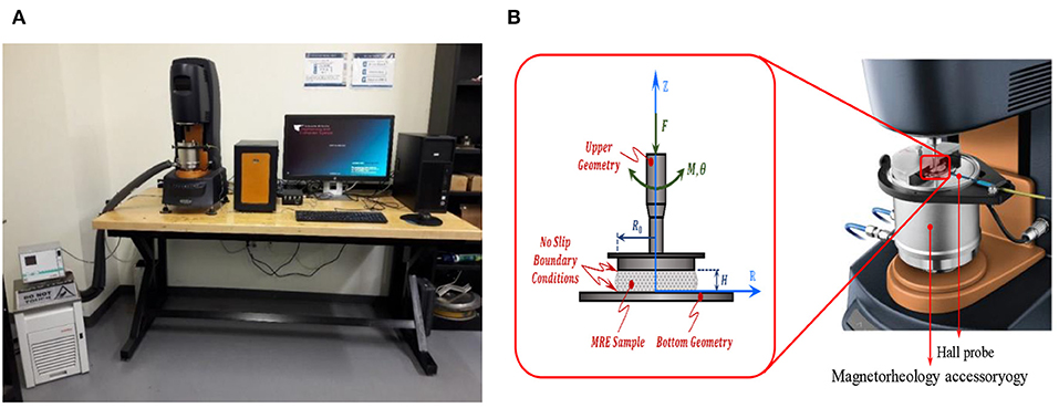
Figure 1. (A) The MRE testing system and (B) schematic diagram of the rotational parallel-plate setup of the rotary rheometer equipped with magnetorheology accessory.
The hysteresis loop, applied force vs. displacement, results of the MRE sample under various levels of applied magnetic flux density are presented in Figure 2. Area inside the hysteresis loop and its major axis represent equivalent damping and stiffness of the MRE, respectively, which as expected are increasing as the applied magnetic field increases. Figure 3 shows the storage and loss moduli with respect to the excitation frequencies under various levels of the applied flux density and fixed shear strain of 15%. Results suggest that storage and loss moduli highly depend on the value of the applied magnetic field, while their dependency on the excitation frequency is not considerable in the frequency range of 1–10 Hz. The dependence of the storage and loss moduli with respect to the shear strain amplitude (2–30%) under the fixed excitation frequency of 2.0 Hz is presented in Figure 4, which clearly shows that the MRE operating under a higher shear strain has a smaller MR effect, and that storage and loss moduli decrease by increasing the strain amplitude. The effect of the applied magnetic field on the storage and loss moduli with an excitation frequency of 2 HZ and the strain amplitude of 15% and its corresponding curve fitting results are further investigated in Figure 5. The results clearly show that storage and loss moduli increase monotonically and considerably by increasing the applied magnetic flux density, however they are subject to saturation for magnetic flux density nearly beyond 1.0 T. This is mainly because the CIPs magnetically saturate as the applied magnetic flux density reaches 1.0 T. It is noted that storage and loss moduli vary from 62.2 (KPa) and 13.3 (KPa) at 0 T to 235.6 (KPa) and 69.0 (KPa) at 1 T, respectively, demonstrating the relative MR effect of 379 and 519% for storage and loss moduli, respectively.
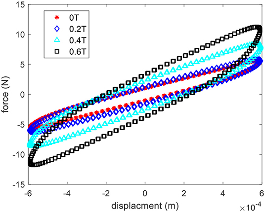
Figure 2. The force with respect to displacement under different levels of applied magnetic flux density and fixed frequency of 1 Hz.
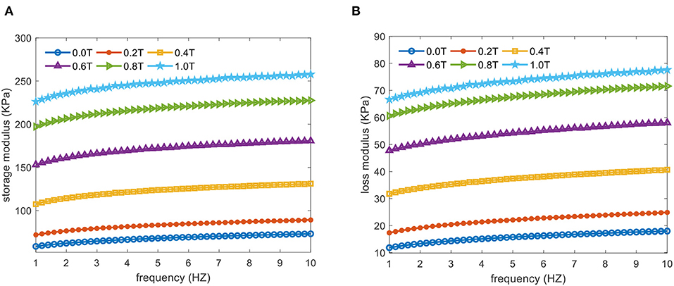
Figure 3. (A) Storage and (B) loss moduli compared to excitation frequencies under various levels of applied magnetic flux density and fixed shear strain amplitude of 15%.
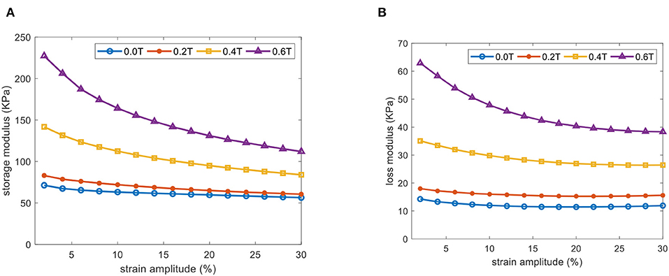
Figure 4. (A) Storage and (B) loss moduli with respect to shear strain amplitudes under various levels of applied magnetic flux density and fixed frequency of 2 Hz.
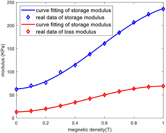
Figure 5. Storage and loss moduli in the presence of varied magnetic flux density with the fixed frequency of 2 Hz and shear strain amplitude of 15% and its corresponding curve fitting results.
Using the experimental data shown in Figure 5, a cubic polynomial function is derived to approximate the variation of the storage modulus with respect to the applied magnetic flux density as:
where G′ and T are the storage modulus in kPa and the applied magnetic flux density in T, respectively. The constant parameters a1 = −234.3, b1 = 396.7, c1 = 10.94, and d1 = 63.04 are identified using the least square method. The approximated function of the loss modulus vs. magnetic flux density is also derived by using a cubic polynomial function, which can be described as:
where G″ is the loss modulus in kPa. Similarly, the constant parameters a2 = −103.2, b2 = 151.1, c3 = 7.79, and d4 = 13.27 are identified using the least square method. The results obtained using the models presented in Equations (1) and (2) are compared with those measured experimentally in Figure 5.
Analytical Modeling of MRE Based Adaptive Seat Isolator
The schematic diagram of the MRE-based seat suspension isolator operating in shear mode is presented in Figure 6A. The proposed isolator includes two MRE layers connecting the seat frame through two permanent magnets to the core base. The applied magnetic flux density is controlled by varying the current input to the electromagnet coils and is guided through the magnetic base into the MRE layers. It is noted that the two permanent magnets are mounted next to the MRE layers in order to extend the working range of the magnetic flux density. The embedded permanent magnets also enhance the stiffness of the MRE layers in the absence of applied current to the coils, which subsequently reduces the static deformation of the MREs, due to the weight of the seat and driver. Moreover, the stoke limit design is considered for the MRE-based seat isolator to make sure MREs do not undergo very large deformation.
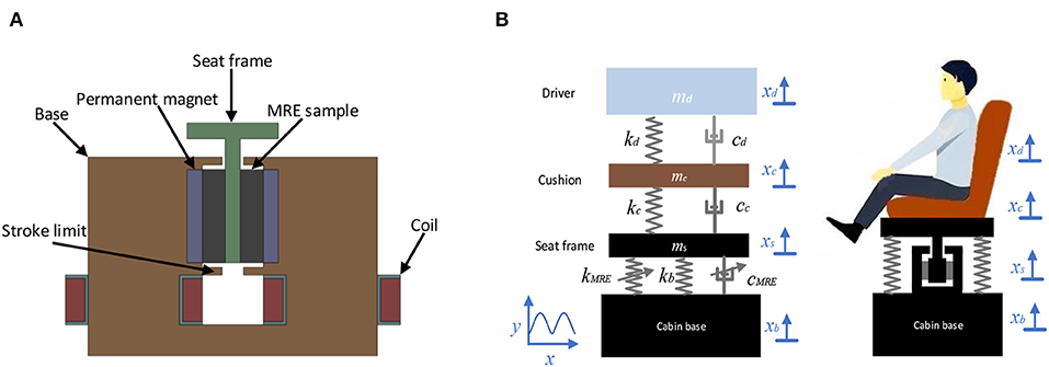
Figure 6. (A) Schematic diagrams of MRE-based seat suspension isolator and (B) the modeling of the MRE-based seat isolation system.
The schematic diagram of the driver seat equipped with the proposed MRE-based seat suspension isolator and its equivalent mechanical system are shown in Figure 6B, in which m, k, and c represent mass, stiffness, and damping of the elements, respectively, and the subscripts d, c, and s denote the driver, cushion, and seat frame, respectively. The equivalent stiffness and damping of the MRE-based isolator are denoted by kMRE and cMRE, respectively. An extra linear spring kb is added in parallel to the MREs to reduce the static deformation of the MRE layers due to the weight of the seat and driver. The dynamics modeling of the MRE-based seat suspension system can be described as:
Let us define:
where kmin and cmin are the equivalent stiffness and damping of the MRE-based isolator in absence of applied magnetic flux density, respectively. △k, △c are the change in the stiffness and the damping coefficients due to the applied magnetic field. Considering the two MREs in the MRE-based isolators, the equivalent stiffness, kMRE, and damping, cMRE, can be described as Li et al. (2013) and Yang et al. (2014):
where A and h are the area and thickness of the MRE operating in shear mode, respectively, and ω denotes the excitation frequency in rad/s. Substituting the Equations (1) and (2) into Equations (8) and (9), respectively, yields the equivalent stiffness and damping as a function of applied magnetic flux density as follows:
Substituting kMRE and cMRE from Equations (6) and (7) into Equation (3) yields:
where fMRE is the generated actuation force induced by MREs in the presence of the applied field and is described as:
Using Equations (1) and (2), and knowing that and , fMRE can be obtained as:
It can be realized from Equation (14) that the proposed MRE-based seat suspension isolator has complex non-linear dynamics, and the actuation force of the MRE can be adjusted by the ratio of A/h and magnitude of the magnetic flux density generated at the location of the MREs. It should be noted that by increasing A/h, the bandwidth of the generated actuation force will also increase. However, increasing the A or h results in a bulkier and heavier electromagnet to generate the required uniform magnetic field in the MREs. In this study, the effective area, A, and thickness, h, of MREs are selected so that the maximum strain experienced in MREs is limited to 15% while the required magnetic flux density up to 800 mT can be achieved at the location of MREs with an applied current of maximum 3 A.
Magnetostatic analysis is also performed to further examine the capability of the proposed MRE-based isolator to supply the required magnetic flux density. For this purpose, the magnetostatic finite element (FE) model of the isolator is developed using an open-source finite element software (Meeker, 2020). Figure 7 shows the developed FE model of the electromagnet and its dimensions. The electromagnet includes 1010 steel core and two coils each contains 1,800 turns of 18AWG copper wire capable of continuously working under 3.0 A current input. The electromagnet also includes two neodymium (N52) permanent magnets (80 × 80 × 5 mm) placed next to the MRE layers to enhance the applied magnetic field and increase the stiffness of the MREs to reduce the static deformation in the absence of applied current to the coils. It should be noted that the relative permeability of the MRE sample with 25% volume fraction of CIPs is measured as 1.4. The effective area, A, and the thickness, h, of the MREs are selected based on trial and error to respect stiffness, stroke limit, and magnetic field requirements and are found to be 64 cm2 and 1.6 cm. The simulation results for the distribution of the magnetic flux density under 3.0 A current input to the coils are presented in Figure 8B. Results show that the isolator base core properly guides the magnetic field directly through the MRE layers perpendicular to the shear direction. The magnetic flux density at the center of the MRE layers is evaluated and presented in Table 1 for different levels of applied current to the electromagnets. The results reveal that applying 3.0 A current to the coils provides over 800 mT magnetic flux density at the center of MRE layers, while nearly no magnetic field is applied to the MREs by applying 2.5 A negative current. Moreover, the permanent magnets are able to apply 430 mT magnetic flux density to the MRE layers in an off-state situation to prevent large deformation.
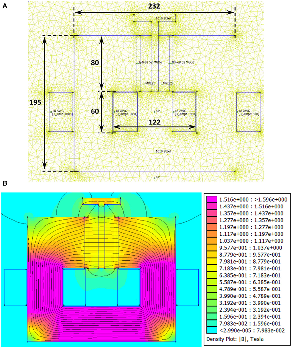
Figure 7. FE magnetic analysis of the MRE-based isolator; (A) FE model and (B) results for 3 A current input to the coils.
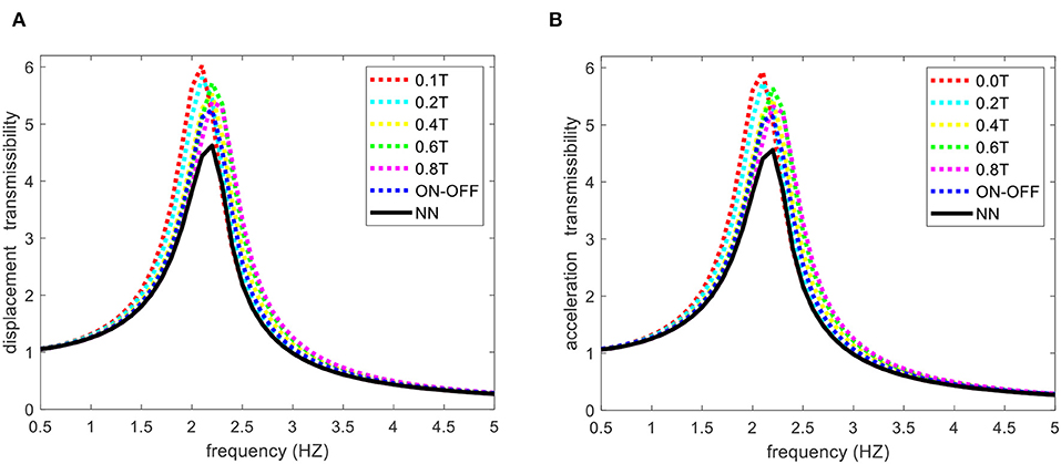
Figure 8. (A) Displacement, and (B) acceleration transmissibility of the human body (xd) with respect to the excitation frequencies in the presence of various controllers.

Table 1. Magnetic flux density at the center of the MRE layers under different levels of applied current to the coils.
Development of the Adaptive Controller Using Neural Network (NN)
In this section, the NN control law is developed to isolate the transmitted vibration to the seat under varying base excitations. The convergence and stability of the proposed control scheme are subsequently verified using the Lyapunov theory.
Neural Network Controller
NN controller is a powerful technique used to address complex non-linear systems under uncertainties (Ge et al., 2002). In the present study, the ideal NN controller output is described as:
where Y(Z) is the unknown dynamics function to be approximated; is the vector of ideal weights; is vector of the basic functions; Z denotes the input variable; l is the number of the NN nodes; ε is the approximation error vector, which is bounded over the compact set, such that ; and is a positive constant. In this study, Gaussian radial basic function Φ(Z) is considered, which can be written as:
where are the centers of the radial basic functions and Rk are the width of the radial basic functions. The estimated weights Ŵ can be presented as:
where is the error vector of the approximated weights.
NN Control Law Design and Stability Analysis
The control objective is to attenuate the transmitted vibration to the seat frame and, subsequently, to the driver. Let us choose the NN input as:
where γ and β are positive constants. The proposed control law is designed as:
where τ and ϑ are positive constant. It is worth noting that the proposed control scheme is model-free. As the accurate dynamic of the MRE-based isolator is generally unavailable in the real application, the model-free control strategy would be beneficial for practical implementation.
The unknown function to be approximated is defined as:
Substituting Equations (20) and (19) along with Equation (17) into Equation (12), we can obtain:
Then substituting Equation (15) into Equation (21), we may write:
In the following, Lyapunov theory has been utilized to prove the convergence and stability of the proposed control scheme. The first Lyapunov function candidate may be selected as:
where φ is a positive constant. Taking the derivative of the first Lyapunov function yields:
The updated law is proposed as:
where σ is a positive constant. Substituting the proposed updated law along with Equation (17) into Equation (24), yields:
Since and ), then we have . Thus, an inequality can be established as:
Choosing the second Lyapunov function as:
and taking its derivative:
and then substitute Equation (22) into Equation (29) yields:
Finally, combining the above two Lyapunov functions, we can write:
Taking derivative of the above Lyapunov function, and considering inequality in Equations (27) and (30), it can be shown that:
The above equation can be simplified as:
where ρ and ϖ are defined as:
Choosing to make sure ρ > 0, then multiplying Equation (33) by eρt, we can obtain:
Integrating Equation (36), yields:
Using Equations (23), (28), and (37), we have the followings identities:
Hence, in the closed-loop system, and xs remain in the compact set and Ωxs, respectively. Considering above, the following theorem can be stated:
Theorem 1: For the governing equation given in Equations (3)–(5), with the control law and update law provided in Equations (19) and (25), respectively, and given that the initial states of the isolation system are bounded and the displacement and velocity of the isolator can be obtained accurately, it can be concluded that the isolator system using the proposed control scheme is semi-global uniformly bounded, which will eventually converge to the original position by appropriately choosing the control parameters.
Proposed Adaptive Neural Network Controller
Using the proposed control scheme and considering that the current of 3.0 A can reach to the maximum applied magnetic flux density (Tmax = 806 mT) and the current of −2.5 A can reach to the minimum applied magnetic flux density (Tmin = 2 mT), as provided in Table 1, the actuation force induced by the MREs can be described as:
where Test is obtained from Equation (14). The control parameters τ and ϑ are identified as 10 and 2, respectively, and the control parameters γ and β in Equation (18) are chosen as 4 and 1, respectively. The centers of the nodes are evenly distributed in [−0.5, 0.5] and the width of the centers Rk is fixed at 2. The initial weights are chosen as zero. The parameters φ and σ in the updated law are chosen as 2,000 and 0.1, respectively. Two hundred nodes are used for the NN approximation. Note that the provided control parameters comply with the control law design and stability analysis described in section Development of the Adaptive Controller Using Neural Network (NN), and a trial and error method is adopted to select the control parameters to achieve satisfactory control performance.
Sky-Hook Controller
In order to evaluate the effectiveness of the proposed control scheme, its performance is compared with those of the two most widely used vibration isolation control approaches, namely passive control and sky-hook control strategies. In the case of passive control, the MRE-based isolator operates in an OFF- or ON-state in which the applied magnetic flux density is set to its minimum (0.0 T) or maximum (0.8 T) values. From Equation (13), it is clear that in passive control, the stiffness and damping of the MRE-based isolator are constant and the actuation force of a passive system is zero. In sky-hook control, the actuation force is generally described as Gu et al. (2019):
Results and Discussions
The parameters of the MRE-based seat suspension system are provided in Table S1. The parameter values for the mass of the seat and mass, stiffness, and damping of the cushion and driver for the model shown in Figure 6B are obtained from Xu et al. (2018) and Choi and Han (2007). It should be noted that an additional linear spring with spring coefficient of kb is added in parallel to the MRE isolator in order to limit the static deformation of the MREs, and two cuboid MREs operating in shear mode with the effective area of A = 64 cm2 and the thickness of h = 1.6 cm are considered. In addition, a stroke amplitude limit of 5 mm, as shown in Figure 6, has been considered. Thus, we can write:
In the following, the effectiveness of the proposed control is demonstrated under different types of base excitations.
Harmonic Excitation
The performance of the proposed controller is investigated under harmonic excitation. The simulation is conducted in the frequency range of 0.5 to 5 Hz, which is the typical frequency range of a vehicle seat suspension system. Five cycles with a constant amplitude of 5 mm are considered for each excitation frequency. The Root-Mean-Square (RMS) values of the displacement and acceleration with respect to frequencies are shown in Figures 8A,B, respectively. Results clearly show the superior vibration isolation capability of the proposed adaptive NN controller over the various fixed levels of applied magnetic flux density (passive control) and On-Off sky-hook controller. The control output using On-Off and the adaptive NN controller are also provided in Figures 9A,B, respectively. As it can be realized, the high-speed control input switching, which may cause high energy loss in the electrical system, occurs using the On-Off control strategy. The RMS value of the displacement, acceleration, and transmissibility at the resonance frequency are provided in Table 2. Results clearly demonstrate the prominent vibration isolation ability of the proposed control scheme at the resonance frequency compared with passive control and On-Off control strategies.
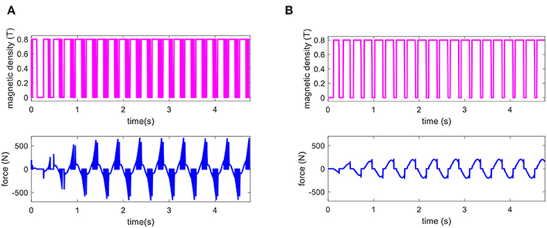
Figure 9. The control input to the MRE-based isolator for harmonic excitation; (A) ON-OFF controller, and (B) adaptive NN controller.
Table 2. Comparison of the performance of various control schemes under harmonic excitation, bump shock, and random excitation.
Bump Shock
In this section, the performance of the adaptive NN controller on the transient response of the designed MRE-based seat suspension isolator is evaluated using the bump shock excitation described as:
where h0 = 0.01 m denotes the height of the bump shock transferred to the seat and wb = 20 is a constant determining the width of the bump. The displacement responses of the seat suspension system to the bump shock using OFF and ON states passive control, on-off skyhook control, and the proposed adaptive NN strategies are provided in Figures S1A–D, respectively. The displacement and acceleration responses of the driver's mass to the bump shock using the proposed control strategy and its comparison with passive off/on and sky-hook control strategies are shown in Figures 10A,B, respectively. The performance comparison results of various control schemes under the bump shock using the max peak of displacement and acceleration values are also listed in Table 2. Results clearly show the superior performance of the proposed adaptive NN control scheme compared with other control strategies in reducing both displacement and acceleration. The corresponding control output of the ON-OFF control strategy and the adaptive NN controller are also presented in Figures 11A,B, respectively. As it can be realized from Figure 11A, after transient bump duration, the ON-OFF control output is basically equivalent to ON state passive control. This is because the ON-OFF control law is based on the relative velocity between the base and seat frame as well as the velocity of the seat frame. Once the base excitation approaches zero, the control output is set to its maximum value. However, as shown in Figure 11B, the adaptive NN control, which possesses the self-learning ability, shows a variation on the control input based on its control law and update law. Considering that the applied magnetic field to the MRE layers is limited between 0.0 to 0.8 T, the control output and, consequently, the actuation force induced by MREs in the presence of the applied field vary between the minimum and maximum values.
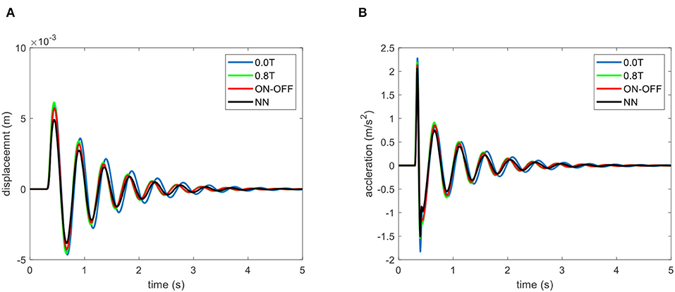
Figure 10. (A) Displacement, and (B) acceleration of the human body (xd) for bump shock input in the presence of various controllers.
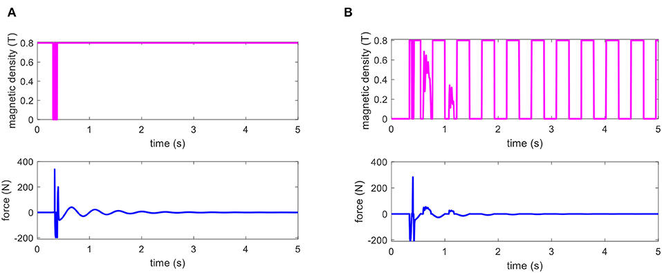
Figure 11. The control input to the MRE-based isolator for bump shock; (A) ON-OFF controller, and (B) adaptive NN controller.
Random Excitation
In this case, the random excitation is provided to further investigate the control performance of various control schemes. The displacement responses of the designed seat suspension system under random excitation using OFF and ON states passive control, on-off skyhook control, and the proposed adaptive NN strategies under the random excitation are provided in Figures S2A–D, respectively. As it can be seen, the developed MRE-based isolator can efficiently suppress the random excitation due to the road profile, and the proposed adaptive NN controller presents better performance compared with passive and on-off control strategies. The prominent performance of the developed controller can also be further verified in Figure 12, in which the displacement and acceleration response of the driver mass obtained using the proposed controller compared with those of the passive OFF/ON and sky-hook control strategies. The RMS values of the displacement and acceleration of the driver mass are also provided in Table 2. The results show that the proposed control scheme can reduce the transmitted vibration to a greater extent than passive and On-Off sky-hook controllers under the random road profile. Comparing the corresponding control outputs of the sky-hook and adaptive NN controllers in Figure 13 also shows the effectiveness of the adaptive NN controller in reducing the required control force and, subsequently, decreasing the consumed energy.
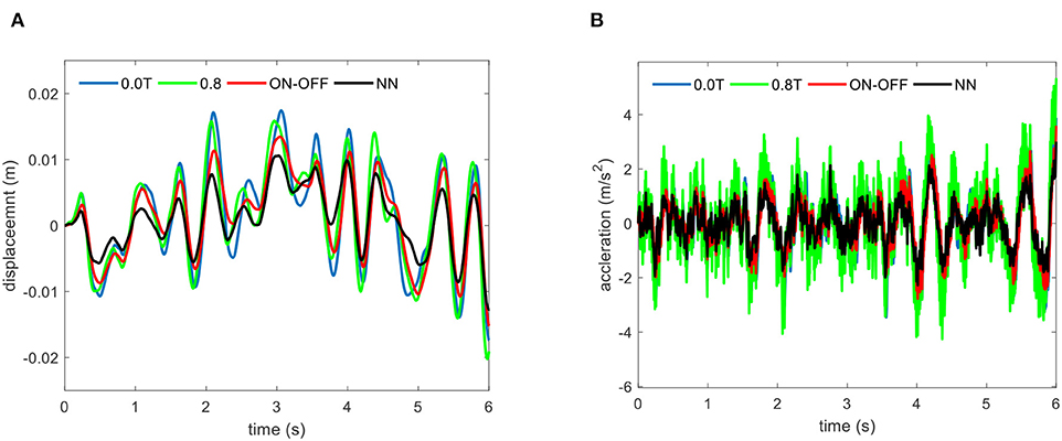
Figure 12. (A) Displacement, and (B) acceleration of the human body (xd) for a random excitation case in the presence of various controllers.
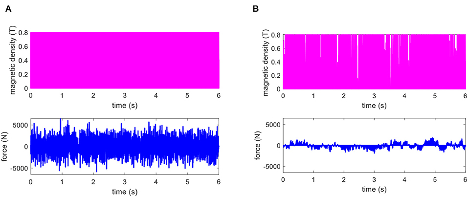
Figure 13. The control input to the MRE-based isolator for random excitation; (A) ON-OFF controller, and (B) adaptive NN controller.
Conclusion
In this study, MRE samples with 25% volume fraction of carbonyl iron particles were fabricated and then experimentally characterized to evaluate their viscoelastic properties and their variation with respect to the applied magnetic field. An MRE-based seat suspension isolator has been developed considering the constraints on the applied magnetic flux density, stroke limit, damping effect, and static deformation. Adaptive NN control was proposed for the MRE-based seat suspension isolator to alleviate unwanted vibration. The stability and convergence of the proposed control scheme were proven using the Lyapunov method. The superior control performance of the proposed control scheme has then been verified under various base excitation profiles through the comparison with passive control and On-Off control strategies. Results suggest the superior performance of the proposed adaptive NN-based control strategy.
Data Availability Statement
The raw data supporting the conclusions of this article will be made available by the authors, without undue reservation, to any qualified researcher upon request.
Author Contributions
CL, MH, RS, and GW contributed conception and design of the study. CL developed the modeling of MRE-based isolator and semi-active adaptive neural network controller. MH developed magnetic analysis, MRE fabrication, testing, and characterization. RS and GW supervised the research study. CL wrote the first draft of the manuscript. All authors contributed to manuscript revision, read, and approved the submitted version.
Conflict of Interest
The authors declare that the research was conducted in the absence of any commercial or financial relationships that could be construed as a potential conflict of interest.
Acknowledgments
Support from the Natural Sciences and Engineering Research Council of Canada (NSERC) and National Natural Science Foundation of China (11832009) are gratefully acknowledged.
Supplementary Material
The Supplementary Material for this article can be found online at: https://www.frontiersin.org/articles/10.3389/fmats.2020.00171/full#supplementary-material
References
Behrooz, M., Wang, X., and Gordaninejad, F. (2014). Performance of a new magnetorheological elastomer isolation system. Smart Mater. Struct. 23:045014. doi: 10.1088/0964-1726/23/4/045014
Choi, S. B., and Han, Y. M. (2007). Vibration control of electrorheological seat suspension with human- body model using sliding mode control. J. Sound Vib. 303, 391–404. doi: 10.1016/j.jsv.2007.01.027
Choi, S. B., Nam, M. H., and Lee, B. K. (2001). Vibration control of a MR seat damper for commercial vehicles. J. Intell. Mater. Syst. Struct. 11, 936–944. doi: 10.1177/104538900772664242
Dargahi, A., Rakheja, S., and Sedaghati, R. (2019a). Development of a field dependent Prandtl-Ishlinskii model for magnetorheological elastomers. Mater. Des. 166:107608. doi: 10.1016/j.matdes.2019.107608
Dargahi, A., Sedaghati, R., and Rakheja, S. (2019b). On the properties of magnetorheological elastomers in shear mode: design, fabrication and characterization. Compos. Part B Eng. 159, 269–283. doi: 10.1016/j.compositesb.2018.09.080
Deng, H., and Gong, X. (2008). Application of magnetorheological elastomer to vibration absorber. Commun. Nonlinear Sci. Numer. Simul. 13, 1938–1947. doi: 10.1016/j.cnsns.2007.03.024
Du, H., Li, W., and Zhang, N. (2011). Semi-active variable stiffness vibration control of vehicle seat suspension using an MR elastomer isolator. Smart Mater. Struct. 20:105003. doi: 10.1088/0964-1726/20/10/105003
Fu, J., Li, P., Wang, Y., Liao, G., and Yu, M. (2016a). Model-free fuzzy control of a magnetorheological elastomer vibration isolation system: analysis and experimental evaluation. Smart Mater. Struct. 25:035030. doi: 10.1088/0964-1726/25/3/035030
Fu, J., Liao, G., Yu, M., Li, P., and Lai, J. (2016b). NARX neural network modeling and robustness analysis of magnetorheological elastomer isolator. Smart Mater. Struct. 25:125019. doi: 10.1088/0964-1726/25/12/125019
Ge, S. S., Hang, C. C., Lee, T. H., and Zhang, T. (2002). Stable Adaptive Neural Network Control. Boston, MA: Springer. doi: 10.1007/978-1-4757-6577-9
Gu, X., Yu, Y., Li, J., and Li, Y. (2017). Semi-active control of magnetorheological elastomer base isolation system utilising learning-based inverse model. J. Sound Vib. 406, 346–362. doi: 10.1016/j.jsv.2017.06.023
Gu, X., Yu, Y., Li, Y., Li, J., Askari, M., and Samali, B. (2019). Experimental study of semi-active magnetorheological elastomer base isolation system using optimal neuro fuzzy logic control. Mech. Syst. Signal Process. 119, 380–398. doi: 10.1016/j.ymssp.2018.10.001
He, W., and Dong, Y. (2018). Adaptive fuzzy neural network control for a constrained robot using impedance learning. IEEE Trans. Neural Netw. Learn. Syst. 29, 1174–1186. doi: 10.1109/TNNLS.2017.2665581
Kallio, M., Lindroos, T., Aalto, S., Järvinen, E., Kärnä, T., and Meinander, T. (2007). Dynamic compression testing of a tunable spring element consisting of a magnetorheological elastomer. Smart Mater. Struct. 16, 506–514 doi: 10.1088/0964-1726/16/2/032
Li, Y., Li, J., Li, W., and Du, H. (2014). A state-of-the-art review on magnetorheological elastomer devices. Smart Mater. Struct. 23:123001 doi: 10.1088/0964-1726/23/12/123001
Li, Y., Li, J., Tian, T., and Li, W. (2013). A highly adjustable magnetorheological elastomer base isolator for applications of real-time adaptive control. Smart Mater. Struct. 22:095020. doi: 10.1088/0964-1726/22/9/095020
Liao, G. J., Gong, X. L., Xuan, S. H., Kang, C. J., and Zong, L. H. (2012). Development of a real-time tunable stiffness and damping vibration isolator based on magnetorheological elastomer. J. Intell. Mater. Syst. Struct. 23, 25–33. doi: 10.1177/1045389X11429853
Meeker, D. (2020). Finite Element Method Magnetics (FEMM 4.0.1) [Online]. Available online at: http://www.femm.info (accessed February 10, 2020).
Nguyen, S. D., Nguyen, Q. H., and Choi, S. B. (2015). A hybrid clustering based fuzzy structure for vibration control - Part 2: an application to semi-active vehicle seat-suspension system. Mech. Syst. Signal Process. 56, 288–301. doi: 10.1016/j.ymssp.2014.10.019
Nguyen, X. B., Komatsuzaki, T., Iwata, Y., and Asanuma, H. (2018). Modeling and semi-active fuzzy control of magnetorheological elastomer-based isolator for seismic response reduction. Mech. Syst. Signal Process. 101, 449–466. doi: 10.1016/j.ymssp.2017.08.040
Noriega, J. R., and Wang, H. (1998). A direct adaptive neural-network control for unknown nonlinear systems and Its application. IEEE Trans. Neural Netw. 9, 27–34. doi: 10.1109/72.655026
Opie, S., and Yim, W. (2009). “Design and control of a real-time variable stiffness vibration isolator,” in IEEE/ASME International Conference On Advanced Intelligent Mechatronics, AIM (Singapore), 380–385. doi: 10.1109/AIM.2009.5229983
Symans, M. D., and Constantinou, M. C. (1999). Semi-active control systems for seismic protection of structures: a state-of-the-art review. Eng. Struct. 21, 469–487. doi: 10.1016/S0141-0296(97)00225-3
Wilder, D., Magnusson, M. L., Fenwick, J., and Pope, M. (1994). The effect of posture and seat suspension design on discomfort and back muscle fatigue during simulated truck driving. Appl. Ergon. 25, 66–76. doi: 10.1016/0003-6870(94)90067-1
Xu, L., Zou, A., Fu, J., Yu, M., and Bai, J. (2018). “Development and simulation evaluation of a magnetorheological elastomer isolator for transformer vibration control,” in Proceedings of 30th Chinese Control and Decision Conference CCDC 2018 (Shenyang), 2600–2604.
Keywords: magnetorheological elastomer (MRE), MRE-based isolator, seat suspension, adaptive neural network control, Lyapunov method
Citation: Liu C, Hemmatian M, Sedaghati R and Wen G (2020) Development and Control of Magnetorheological Elastomer-Based Semi-active Seat Suspension Isolator Using Adaptive Neural Network. Front. Mater. 7:171. doi: 10.3389/fmats.2020.00171
Received: 04 March 2020; Accepted: 11 May 2020;
Published: 26 June 2020.
Edited by:
Miao Yu, Chongqing University, ChinaReviewed by:
Xufeng Dong, Dalian University of Technology, ChinaYu Tian, Tsinghua University, China
Copyright © 2020 Liu, Hemmatian, Sedaghati and Wen. This is an open-access article distributed under the terms of the Creative Commons Attribution License (CC BY). The use, distribution or reproduction in other forums is permitted, provided the original author(s) and the copyright owner(s) are credited and that the original publication in this journal is cited, in accordance with accepted academic practice. No use, distribution or reproduction is permitted which does not comply with these terms.
*Correspondence: Masoud Hemmatian, bWFzb3VkLmhlbW1hdGlhbkBjb25jb3JkaWEuY2E=