 Betina M. P. Ferreira1
 Niklas Andersson1Erik Atterling1Jonas Engqvist2Stephen Hall2,3
 Cedric Dicko1,3*
- 1Division for Pure and Applied Biochemistry, Department of Chemistry, Lund University, Lund, Sweden
- 2Division for Solid Mechanics, Lund University, Lund, Sweden
- 3Lund Institute for Advanced Neutron and X-ray Science, Lund, Sweden
Three-dimensional scaffolds play an essential role in tissue engineering. Although essential, the tunability of the 3D scaffolds mechanical and transport properties remains a challenge. In this work, we present new approaches to advance the field. First, we applied our progressive pH acidification to mimic the natural silk gelation process before ice-templating (−20 and −80°C); second, we fitted the mechanical properties using a connectivity model; third, we fitted the scaffolds mechanical relaxation to understand the transport properties; and fourth we used micro-CT to correlate the process parameters to the scaffolds' performances. Our results suggested that the free shrinkage of the scaffolds determined their final properties. We found, however, that the porosity (above 90%) was anisotropic, similarly the tortuosity (between 1 and 1.3). We identified two major pore dimensions, the first one between 10 and 20 μm, and the second between 50 and 130 μm. Mechanically, our model suggested that the bulk modulus captured the elastic contribution and was controlled predominantly by the silk concentration. We tentatively associated the fractional modulus 1 to the collapse of the larger pores structures and was controlled mostly by the process temperature. We assigned the slow relaxation to the transport of fluid in the silk sponge scaffolds; and the fast relaxation with a viscoelastic relaxation. The silk concentration and process temperatures did not influence the latter. Overall, our use of the tomography, mechanical test, and detailed statistical analysis provides inroads into the interplay between process parameters (silk concentration and process temperature) and the multiple responses of the silk sponge scaffolds. The development of a new mechanical fitting for the compression test helped capture simply the different failure modes in the sponge scaffolds as well as correlating those events to relaxation and eventually transport properties.
Introduction
Scaffolds are one of the three main components of tissue engineering, along with cells and bioactive molecules (Yang et al., 2001; O'Brien, 2011). A scaffold serves to mimic extracellular matrix (ECM) environments, which provides a surface/volume for cells to attach, and promotes the desirable interactions between them. The challenge, however, is in mimicking the complexity of the human machinery that builds tissues and organs (Langer and Vacanti, 2016). The associated high demands (functional and regulatory) placed on scaffolds have limited their success. Indeed, a scaffold (Griffith and Naughton, 2002; DeBari and Abbott, 2019) need to be biocompatible, have suitable mechanical properties, be permeable to fluids, and easy to manufacture to be commercially successful (Howard et al., 2008). Additionally, the scaffolds must facilitate angiogenesis (the ingrowth of blood vessels) once implanted (Varley et al., 2016).
The fabrication of 3-dimensional (3D) scaffolds are central to tissue engineering, and several process strategies already exist. For example: rapid prototyping, gas foaming, salt leaching, fiber bonding, and ice-templating, to name a few (Yang et al., 2001; Elahi et al., 2017). A judicious combination of the processes and the polymers help to address most applications (Yang et al., 2001; Langer and Vacanti, 2016). Nevertheless, the ice-templating technique (Deville et al., 2006) is the most promising one; only for it can use water as the porogen to generate safe and tunable scaffolds for cell culture and in vivo implants (Wegst et al., 2010; Deville, 2013; Elahi et al., 2017).
Ice templating is a technique used to form a highly complex and porous material from a solution of proteins or other macromolecules. The method uses a solution of the macromolecule, called a “slurry,” that is frozen to a solid. The growing ice crystals form gaps in the slurry, free from the solute, which is the basis of porosity. The forming of crystals is assumed to be randomly distributed and yields a highly complex structure. The frozen solid is immediately freeze-dried. At this step, the solvent is sublimated from the scaffold to produce a foam-like structure (Deville, 2013). By altering the process of the ice template, one can change the outcome of the material properties like different pore sizes and structures (Wegst et al., 2010). Materials obtained by ice-templating are referred to as cryogels (Okay and Lozinsky, 2014). With cryogelation, the scaffold properties (mechanics and transport) are tuned by altering the temperature of the process (freezing regime), the concentration of the polymer, and the solvent used in the process (Okay and Lozinsky, 2014).
The interaction with cells requires, however, more than just correct structures and morphologies. Synthetic polymers cryogels fall short by a lack of favorable interactions with cells; natural polymers, on the other hand, can provide a favorable milieu for the cells to thrive (Tamada, 2005; Reis et al., 2008); and, among them, silk.
Silks, from spiders and insects, has been heavily researched as biomaterials (Vepari and Kaplan, 2007; Holland et al., 2019). On top of being mechanically superior to most other materials, silk is also biodegradable (Vepari and Kaplan, 2007; Rockwood et al., 2011); silk has lower inflammatory responses than other materials (Meinel et al., 2005). Because of its many desirable properties, silk scaffolds have successfully been produced for many different applications, including wound dressings, bone, and cartilage (Vepari and Kaplan, 2007; Rockwood et al., 2011; Holland et al., 2019). The need for degradation in vivo is yet to be quantified, and the scaffold needs to make way for the natural growth of new ECM to form healthy tissue.
Nazarov et al. were the pioneers in preparing 3D scaffolds using regenerated silk fibroin (RSF) and the cryogelation technique (Nazarov et al., 2004). They obtained sponges through three different methods, with one being freeze-drying. They used methanol and propanol to induce β-sheet structures formation, silk natural crosslinking mechanism. Several improvements to their initial process followed (Makaya et al., 2009; Min et al., 2009; Rajkhowa et al., 2010; Kadakia et al., 2016; Ming et al., 2016). For example, Tamada et al. prepared different 3D silk scaffolds by freezing with different solvents as a porogen and letting them thaw at room temperature (Tamada, 2005). Cho et al. prepared new silk fibroin scaffolds by freeze-drying and studied the effect on the pore microstructure by altering the pH during the gelation step (Cho et al., 2012). Together, the efforts have been toward greater control of the morphologies (porosity and tortuosity) and the associated mechanics. Until recently, the 3D scaffolds were mechanically weak (in the kPa range); Ak et al. used ethylene glycol diglycidyl ether to prepare RSF scaffolds with a very high compressive modulus of 50 MPa (Ak et al., 2013). The counterpart was poor transport properties. Mallepally et al. in 2015, prepared RSF aerogels with CO2 as a volatile acidifying sol-gel accelerator; and obtained mechanically tunable scaffolds (up to 174 kPa) with a very high surface area (Mallepally et al., 2015).
Although successful in achieving higher mechanical properties or high transport, accessing scaffolds with high mechanical and high transport properties remains elusive. A measure of success is the level and quality of the scaffold vascularization.
The vascularization in the 3D scaffolds is one of the essential features in a scaffold (Reis et al., 2008; Lovett et al., 2009). For porous biomaterials, the porosity has to be higher than 40% (Wegst et al., 2010), and the material needs to have sufficient stiffness. Still, strength and toughness to mimic the required function for a certain amount of time, depending on the application (Wegst et al., 2010). For each purpose, there are unique associated requirements to be fulfilled (Reis et al., 2008). In regenerative medicine, vascularization is crucial for the cells; 200 μm is the maximum distance from the nearest capillary needed for a cell to survive for an extended period (Lovett et al., 2009; Zhang et al., 2015). For the cartilage and bone tissue engineering field, a wide range of pores and interconnectivity are necessary for a successful scaffold implantation (Griffon et al., 2006; Ribeiro et al., 2019). Generally, larger interconnected pores (300–500 μm) promotes good exchange of nutrients, but not necessarily an adequate cellular growth, while smaller pores (<50 μm) can promote adequate cell adhesion and short-term proliferation (Griffon et al., 2006; Ribeiro et al., 2018, 2019). The interconnection and orientation of the pores are yet to be achieved and understood (Zhu et al., 2014; Qi et al., 2017; DeBari and Abbott, 2019). Mathematical modeling is also a challenge. Only a few articles include numerical analysis in their studies. In 2017, from a query search for “hydrogels and characterization” in the Web of Science database, only 1% of the articles used mathematical models to describe their results (Caccavo et al., 2018).
In 2017, Panda et al. obtained RSF sponges with oriented porous channels using a freeze-casting method (Panda et al., 2017). The mechanical properties (experimental and predicted) did not, however, correlate with the microstructure of the sponges (Panda et al., 2018). Kolahreez and Morshed concluded similarly (Kolahreez and Morshed, 2018). The new commonality with those studies is the lack of accurate 3D structures. In a bid to quantify transport and mechanics, Maniglio et al. used N2O foaming (Maniglio et al., 2018) to prepare 3D RSF hydrogel scaffolds in vivo. They investigated them by micro-computed tomography (micro-CT). They found a correlation between the 3D architecture and the mechanical properties when they controlled the RSF β-sheet structures content. Ribeiro et al. used a salt-leaching and freeze-drying approach to produce 3D scaffolds and correlated the morphology (micro CT) to the mechanics and cell performance (Ribeiro et al., 2019). The study highlighted a gradient in porosity and subsequent gradient in functional responses.
In this work, we present new approaches to advance the field. First, we applied our progressive pH acidification to mimic the natural silk gelation process before ice-templating; second, we fitted the mechanical properties using a connectivity model; third, we fit the scaffolds mechanical relaxation to understand the transport properties; and fourth we use micro-CT to correlate the process parameters to the scaffolds' performances.
Materials and Methods
Degummed silk fibers from Mulberry (Bombyx mori), were obtained from an online silk supplier (Wild Fibres, http://www.wildfibres.co.uk). Glucono-δ-lactone (GDL) was purchased from Sigma Aldrich and used directly.
Sponge Scaffold Preparation
Regenerated Silk fibroin (RSF) was prepared using a modified protocol described by Rockwood et al. (2011). Briefly, 1 g of degummed silk fibers were dissolved in 9 M LiBr (Sigma-Aldrich) at 70°C for 15 min. After dissolution, the solution was left to cool for 5 min and then immediately transferred to a cellulose dialysis tube (Sigma-Aldrich) with a molecular weight cut-off of 12 kDa. The silk solution was dialyzed for 3 days against 10 mM phosphate buffer at pH 7.2. The dialysis buffer was changed once a day. After dialysis, the solution of silk is recovered in a 50 ml falcon tube and centrifuged at 4,000 rpm for 15 min. The final concentration of the solution was determined by oven drying an aliquot.
The gelation of silk was induced using GDL (Del Giudice et al., 2017; Dicko and Del Giudice, in preparation). The acidification using 0.5% GDL mimics the stable cross-links found in Bombyx mori; besides, the progressive acidification allows for a homogeneous gelling of the silk solution.
For sponge scaffold fabrication, 1 ml Henke Sass Wolf Luer syringes with an inner diameter of 4.69 mm, were chosen as the most suitable container to yield the correct form factor, as well as the best alternative to perform the various experimental characterization methods needed. Immediately after mixing the GDL and the silk solutions (Table 1), a small volume of air was drawn into the syringe to prevent the silk solution from touching the syringe plunger; and, ~200 μl silk solution was then withdrawn in the syringe. Lastly, the plunger was moved further up to make sure no silk solution was present in the syringe tip; the samples gelled for 18 h. After gelation, the syringes were placed into freezers at −80 and −20°C, according to Table 1, for 24 h. After freezing, the samples were loaded into a freeze-drier (Labconco Freezone 4.5 L) for 24 h to sublimate the water. The temperature in the desiccator was −45°C, and the pressure was 5 mbar.
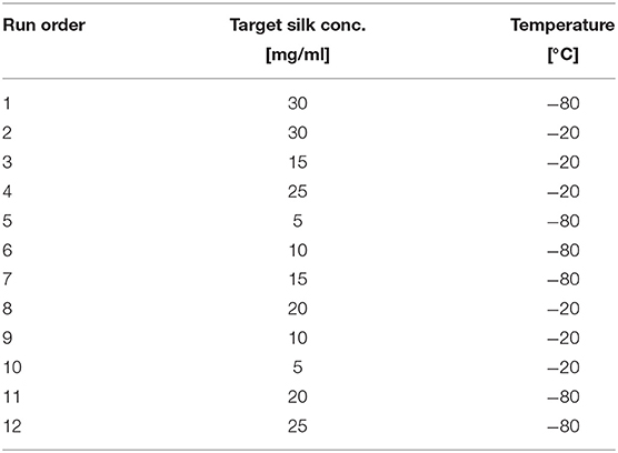
Table 1. Factorial design for the scaffold preparation.
The sponge scaffolds were weighed and imaged after each preparation step. Dimensions of the sponge scaffolds were extracted from images using ImageJ. The calculations were performed in the image processing software Fiji (Schindelin et al., 2012).
Factorial Analysis
Sponge scaffolds were prepared using a full factorial design (Minitab, Minitab Inc.). We used six different silk concentrations and two different end freezing temperatures, summarized in a 2 × 6 factorial table of 12 samples (Table 1). The samples in Table 1 were randomized to eliminate systematic errors occurring during the experiments, and every step in the preparation and characterization of the samples was conducted in this order. For each run, we prepared seven samples.
The analysis of the factorial design consisted of an ANOVA and regression. Briefly, the p-value indicated if a factor has a significant effect on the observable. The factor had a significant impact if the p-value is lower than 0.05. The F-value provided a ranking for the strength of the effects relative to one another. The larger the F-value, the stronger the effect of the factor on the observable. In addition to this, a linear regression combining the factors to explain the observable (a.k.a. response) was computed and reported as Pearson coefficient (R2). The closer the R2 was to 100%, the better the linear fit of the factors to explain the observable. The predictability of the regression was measured by the predicted R2. The closer to 100%, the better for the predicted R2. Interestingly a poor R2 predicted is indicative of a regression model that is not representative of the variance of the observable. The responses from all the characterization methods were evaluated using the Minitab software (Minitab, Inc.).
X-Ray Tomography and Image Analysis
X-ray tomography data were acquired using a Zeiss Xradia XRM520, at the 4D Imaging Lab at Lund University, with a source voltage of 50 kV with 1,601 radiographs over 360 degrees. Tomographic reconstruction provided 3D image volumes of 1,000 × 992 × 1,014 voxels. Voxel dimensions were 3 × 3 × 3 μm3. In the following, 2D sections through the volumes perpendicular to the vertical axis of 992 × 1,014 pixels are referred to as “slices.” We imaged every scaffold in the dry state, the top 100 and bottom 100 slices were discarded from the analysis to minimize edge effects. The remaining 800 slices were analyzed using Fiji (ImageJ, NIH) and TauFactor (Cooper et al., 2016). The method of pre-processing the images (Fiji) consisted of (i) adjusting the brightness, (ii) applying a threshold, and (iii) removing noise using the “remove outliers” function. The porosity and tortuosity of the stack of 2D images were calculated using TauFactor.
Fast Fourier Transform (FFT) Processing
FFT processing of the images was carried out to obtain quantitative information about the average size of the objects exhibiting an absorption contrast in the scaffold. The FFT was performed on the thresholded images and averaged through the stack (Blaise et al., 2010). Before the FFT, the images were truncated to 822 × 844 pixels to avoid any edge effects. The average FFT images were then radially averaged to produce a one-dimensional radial profile. The analysis was performed using the conventional 2D FFT routine of Matlab. The one-dimensional profile was then interpreted as a small- and wide-angle X-ray scattering. Here we reported the various correlation lengths found in the scaffold.
Permeability
The experimental setup used a modified version of the falling head gravity-based method with the adapted Darcy's law of Pennella et al. (2013). By using this modified setup, the hydraulic conductivity, K, and permeability, k, could be calculated, see (2), (3). Hydraulic conductivity is a measure of how easily water flows through a porous medium, whereas permeability measures how well a material can transmit a fluid. Thus, the permeability has nothing to do with the liquid itself; instead, it is an intrinsic property of the material.
The volumetric flow through the porous medium is given by (1),
where Q is the volumetric flow throw the porous medium, is the hydraulic gradient, A is the cross-sectional area of the scaffold, H is the distance between two free water surfaces, and L is the height of the scaffold. With a moving water column, H translates to H1 (H at time t = 0) and H2 (H at time t = T) after integration of (1), which yields the expression for the hydraulic conductivity, K:
In (2), a is the cross-sectional area of the standpipe, t is the duration of the experiment (i.e., the time it takes for the water column to move from H1 to H2). The time (t) was measured in the experiment, as well as the height of each scaffold. The other parameters in (2) were kept constant.
Once we obtained the hydraulic conductivity K, we calculated the permeability k as follows:
μ is the viscosity of water, ρ is the density of water, and g is the gravitational constant.
Fourier-Transform Infrared Spectroscopy (FTIR)
FTIR spectra of the sponge scaffolds were acquired using a Nicolet iS5 FTIR Spectrometer. We collected three spectra for each sponge scaffold: at the bottom, middle, and top. Rapid comparison of the three positions allowed us to examine the anisotropic properties of the samples. Each spectrum was the average of 32 scans from 550 to 4,000 cm−1 at a resolution of 4 cm−1.
The FTIR-ATR spectra were further processed to extract four structural parameters, namely: the crystallinity degree, the tyrosine ratio, and the amide I/II ratio. We calculated the crystallinity degree (Bhat and Nadiger, 1980) of silk fibers by comparing the peaks' intensities at 1,263 and 1,230 cm−1 as follows:
Where A1263 and A1230 are the intensities of the peaks at 1,263 and 1,230 cm−1 respectively.
The tyrosine ratio was calculated by estimating the area under the tyrosine peaks at ± 830 and ± 850 cm−1 and computing the ratio of intensities at 850 / 830 cm−1. The weak features at ± 850 and ± 830 cm−1 make a doublet attributed to Fermi resonance of the aromatic side chain of the tyrosine residue. The ratio is indicative of the local environment of tyrosine residues within the fibers and by extension, the local environment of the amorphous regions of the silks (Monti et al., 1998).
Further, the ratio of the maximum intensities of amide I (at around 1,640 cm−1) and II (at about 1,540 cm−1) peaks was calculated to estimate the total change in secondary structure upon treatment (Ishida and Griffiths, 1993; Boulet-Audet et al., 2015). Also, the amide I region (1,600–1,700 cm−1) was deconvoluted to extract the secondary structure composition of the silks.
Mechanical Tests and Analysis
For the mechanical tests, we used a Mach-1 System model V500c from Biomomentum. The load cell had a nominal maximum load of 1.5 N and a resolution of 75 μN. The mechanical tests were performed in the same syringes that the sponges were cast in, to avoid any destruction or alteration of the intricate architecture of the sponge. The measurements were performed on the wet sponge scaffolds. Initial measurements showed that in the dry state, the sponges were too brittle for any reliable analysis. We conducted a compression test with a 3 mm cylindrical flat-ended indenter. In the low strain regime (<10%), we assumed that the compression was unconfined. For each sample, we equilibrated the sponge scaffolds in double-distilled water for 48 h; then, the samples were compressed at a velocity of 0.005 mm/s and relaxed. We applied three cycles of compression and relaxation consecutively. After each relaxation ramp (changes in force <0.001 gf/min), the samples were dynamically compressed at 0.5 Hz with an oscillatory amplitude of 0.1 mm. The procedure was repeated two times at 1 and 2 mm depth. The initial contact criterion was 0.1 gf with a stage velocity of 0.02 mm/s.
Compression Test Analysis
To analyze the stress-strain curve, we use the approach developed by Chen et al. (2010). The model was initially derived to relate silk cocoon connectivity and mechanical properties. Briefly, the model describes a shared feature, namely the apparent control of mechanical properties by loss of connectivity of bonding between component materials. The model assumes several different activation effects (i.e., with fractional contribution fi). The relation between stress, σ, and the initial composite modulus Y becomes:
Where , with Yi and εai the associated modulus and activation strains, respectively. The force-displacement curve was transformed into stress and strain by normalizing with the cross-sectional area and the initial length of the scaffold, respectively. We determined the number of activations by a brute force method to obtain the Yi and εai. The experimental data were fitted using one, two, or three activations; and the outcome of each model (χ2) in a pair-wise manner (F-test) to determine which of the model did not overfit the experimental data.
Stress Relaxation Analysis
We use here a simple framework inspired by Meghezi et al. (2017). We modeled the load (L) relaxation by a sum of three exponential decays; with a short, intermediate, and long-time decay contributions as follows:
Where , with η being the viscosity and G the modulus of the material.
Not to overfit the data, we fitted the relaxation curves with one, two, and three decay curves; and the outcome of each model (χ2) in a pair-wise manner (F-test) to determine which of the model did not overfit the experimental data. All the calculations were performed using custom Matlab (The Mathworks Inc.) scripts.
Dynamic Tests
the dynamic test (sinusoid) was analyzed using the Mach-1 Analysis software (Biomomentum SOP04). We extracted the elastic modulus E, storage modulus E', loss modulus E”, and the Phase. The relation between moduli was as follows:
Results
For consistency, but with some restrictions, we prepared all the samples (gelled and freeze-dried) in 1 mL syringes. The unique form factor allowed us to perform all the characterizations (except FTIR-ATR) with a minimum of sample handling. The sample preparation resulted in 84 silk sponge scaffolds, cylindrically shaped of ~1 cm in height. Figure 1 summarizes the experimental workflow.
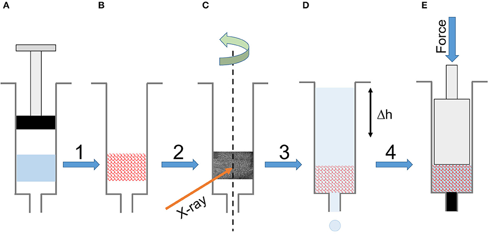
Figure 1. Experimental workflow. (A) The silk solution gelled in a 1 mL syringe. (B) The final scaffold after freezing and freeze-drying. (C) Tomography of the dry scaffold in the syringe. (D) Permeability measurement in the syringe using a timed water column elution. (D) The mechanical compression of the wet scaffold in the syringe.
Remarkably, all of the scaffolds exhibited shrinkage, noticeable to the naked eye, which led to a quantification of this shrinkage (Table 2). The shrinkage proved to be significantly affected by silk concentration (p = 0.006 <0.05) but not statistically by temperature (p = 0.221), see Table 3 for details. Henceforth, we included the shrinkage as a covariate in all the ANOVA analysis.
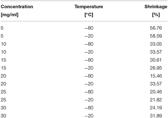
Table 2. Shrinkage of the sponges in different silk concentration and temperature.
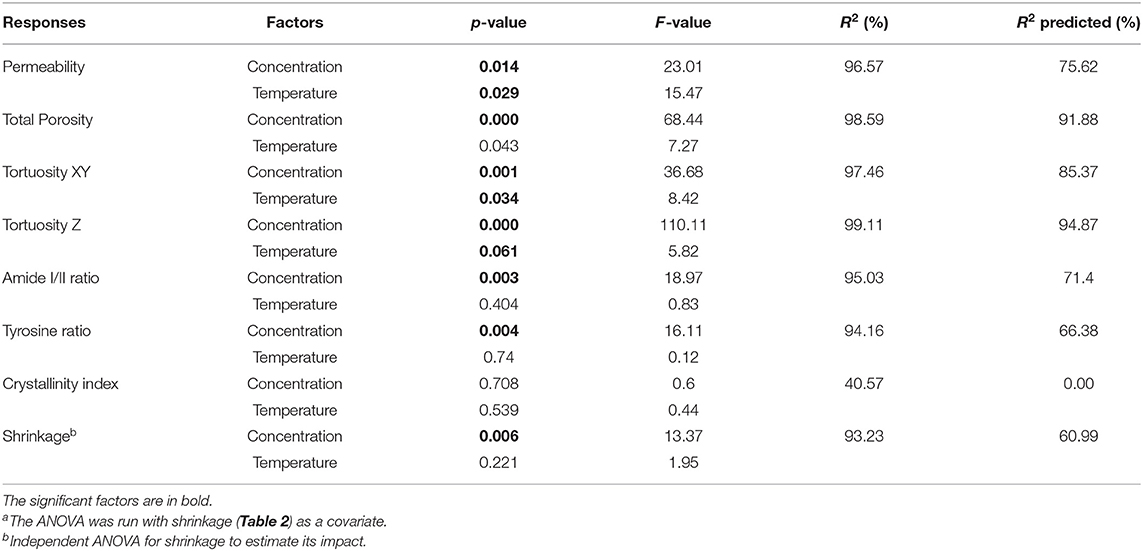
Table 3. ANOVAa and regression analysis of the factorial design responses.
X-Ray Tomography and Image Analysis
Figure 2 shows a typical 3D X-ray tomography image of a sponge scaffold.
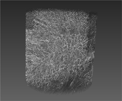
Figure 2. 3D rendering of a silk sponge scaffold reconstructed from computer tomography (CT) slice images. A typical silk sponge scaffold image consisted of 1,000 slices of 992 × 1,014 pixels, at 3 × 3 × 3 μm3 voxel size. The z-axis is along the page vertical direction and the syringe direction.
The image slices from the tomography were then pre-processed using the Fiji software (Schindelin et al., 2012). Figure 3 illustrates the steps.
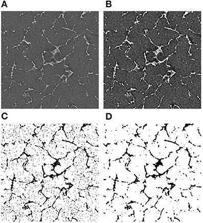
Figure 3. Image processing algorithm for CT images. (A) The original image, (B) the adjusted brightness, (C) the thresholded image, and (D) the final noise-free image. The bright areas represent the silk in (A,B). In the binarized images (C,D), the dark areas represent the silk.
Analysis of Correlation Features
For determining the average size of the objects, images obtained perpendicularly to the z-axis were used (see materials and methods). Figures 4A,B illustrate the one-dimensional radial profiles at −20 and −80°C, respectively. Although featureless, the curves presented three distinct regions (for a pairwise comparison, see Figures S1–S6). First, in the higher q region (i.e., smaller size in real space), all curves regardless of temperature and concentration displayed a small peak. The dimensions were between 4 and 5 μm. We assigned this feature to the thickness of the silk layers in the scaffold. Second, in the mid-q region, we found a broad peak with a varying position. The associated dimensions were between 10 and 20 μm. Third, at low q, we found a mixture of broad and sometimes defined peak.
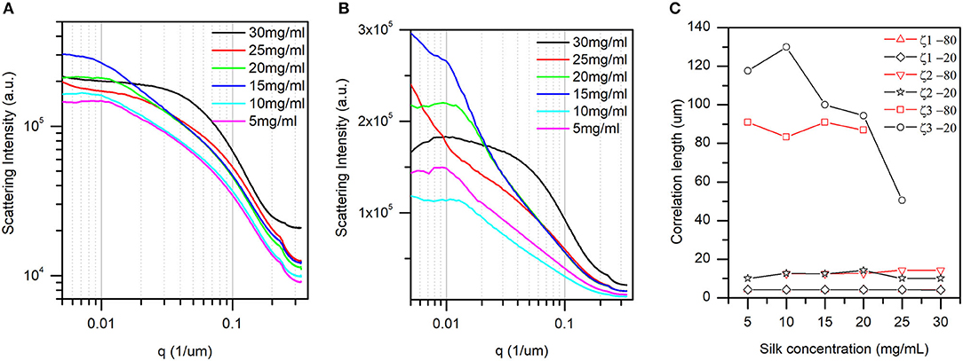
Figure 4. The one-dimensional radial average of the 2D Fourier transform slices (see materials and methods for details). (A) At −20°C, and (B) at −80°C. The pairwise comparison is found in Figures S1–S6. (C) Correlation lengths found at −80°C and −20°C and their dependence with silk concentration. Briefly, the peak positions identified in panel (A,B) are converted to representative dimensions (correlation lengths) in the sponge scaffolds (see text for details). Only correlation length 3 (x3) at −20°C displayed an inverse linear dependence with silk concentration.
The associated dimensions were between 50 and 130 μm. The two last correlation lengths were assigned to pore sizes in the scaffold. Figure 4C shows the dependence of the three correlation lengths with silk concentration and temperature. The inaccuracy in the peak positions in Figures 4A,B precluded any ANOVA. Nevertheless, we found that the silk thickness and the small pore sizes were independent of silk concentration and temperature. In contrast, the larger pore sizes were independent of the silk concentration at −80°C, and decreased in size with silk concentration at −20°C. Note that at concentrations above 25 mg/ml no peaks were discernable in the low q region. The absence of peak could be that the feature was larger than the instrument measurement range, or that the feature simply disappeared in the sample.
Porosity and Tortuosity
The thresholded stack (1,000 slices of Figure 3B type binary images) was then analyzed using TauFactor (Cooper et al., 2016) to extract the total porosity and the tortuosities in the XY plane normal to the z-axis (syringe direction), and the z-axis direction. Figure 5 summarizes the results.
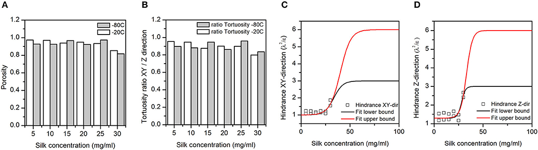
Figure 5. (A) Silk sponge scaffolds' fractional porosity (ε). (B) The ratio of the silk sponge scaffold XY plane to Z-direction tortuosities (λ). A ratio of 1 meant no anisotropy in the tortuosity; a ratio <1 meant a higher tortuosity in the Z-direction as compared to the XY plane. (C,D) Hindrance factor (λ2/ε) in the XY and Z-directions, respectively. The hindrance, or resistance to flow, is tentatively fitted to a sigmoid with lower and upper bounds (three and six) defined by Bombyx mori cocoon hindrance (Horrocks et al., 2013). Note that we pulled the −20 and −80°C hindrance together for the fit.
Panel A in Figure 5 illustrates the dependence of the total porosity with silk concentration and process temperature. The ANOVA was significant for both silk concentration (p = 0.00, F = 68.44) and process temperature (p = 0.043, F = 7.27). Interestingly the effect of the silk concentration on the total porosity was almost 10 times stronger than process temperature. The high regression coefficients confirmed the importance of the two factors in explaining the variance of the total porosity. The tortuosity was defined by the ratio of the real open paths through the sponge scaffolds to its physical dimensions. The tortuosity in the XY plane was defined relative to the diameter of the sponge scaffold; the tortuosity in the Z-direction was defined relative to the sponge scaffold height. The ANOVA was significant for both tortuosities for silk concentration, but only significant in the XY-plane for the process temperature.
Similarly, to the porosity, the silk concentration had a stronger effect as compared to the process temperature (F-values). The regression coefficients were high, as well. Figure 5B goes further with a plot of the anisotropy in tortuosity; with increasing silk concentration, the sponge scaffolds were more tortuous in the Z-direction compared to the XY-plane.
We captured the transport properties by computing the hindrance factor [i.e., λ2/ε (the tortuosity squared divided by the porosity)]. The hindrance factor reflects the resistance to flow in a porous matrix (Epstein, 1989; Moreira and Coury, 2004). We combined the hindrance at −20 and −80°C in the XY plane (Figure 4C) and the Z-direction (Figure 4D). We tentatively fitted the change in hindrance factor using a sigmoid function with upper bounds (three and six) from the Bombyx mori cocoons (Horrocks et al., 2013). We found that in the XY-plane, the hindrance was lower than the lowest hindrance factor found for the Bombyx mori cocoons. In contrast, in the Z-direction at 30 mg/mL of silks, the hindrance factor was comparable to the lowest hindrance factor found for the Bombyx mori cocoons.
Permeability
The permeability of a fluid through a porous scaffold is dependent on porosity, as well as pore size and inter-connectivity of the pores (Horrocks et al., 2013). A permeability test, therefore, describes many different aspects of the scaffold properties that are important to its success once under operation. The results from the scaffold permeability test showed obvious correlations to both the concentration and the end freezing temperature (Figure 6). We excluded the 5 and 10 mg/ml sponge scaffolds because they did not laterally fill the syringe sufficiently. Nevertheless, we observed that the permeability was significantly affected by the concentration of silk (p = 0.014, F = 23.01) and by the temperature (p = 0.029, F = 15.47). The marginally higher F-value for concentration suggested that the silk concentration was more important than the temperature. The regression analysis showed a sufficiently high predicted R2 (75.62%) to predict the permeability.
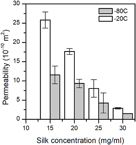
Figure 6. Sponge scaffolds' permeability (n = 3) at different process temperatures and silk concentrations.
Fourier-Transform Infrared Spectroscopy (FTIR)
Figures S7, S8 summarize the raw FTIR-ATR spectra and the extracted parameters (amide I/II ratio, crystallinity degree, tyrosine ratio). Table 3 summarizes the statistical analysis of the FTIR responses. We observed that the concentration had a significant impact on the amide I/II ratio (p = 0.003, F = 18.97), and tyrosine ratio (p = 0.004, F = 16.11); but no significant effect for the process temperature. We found that neither the silk concentration or temperature significantly affected the crystallinity degree. To interpret the observation, we need to understand the interplay between amide I/II ratio, crystallinity degree, and tyrosine ratio. Briefly, the assumption was that a change of structure (i.e., changes in the amide I/II ratio) would be reflected by a change in the amorphous domains of the silk sponge scaffolds (i.e., the tyrosine ratio); and, or by a change in the crystallinity (i.e., crystallinity degree). In our case, we observed a significant effect of concentration on the amide I/II ratio and a significant effect only in the tyrosine ratio. We interpreted, therefore, that the concentration of silk mainly affected the amorphous domains. The high R2 and R2 predicted supported the fact that the concentration predicted a change in structure (Amide I/II ratio). The weaker R2 predicted for the tyrosine ratio suggested instead that another underlying effect was needed to predict the tyrosine ratio from solely the concentration.
Mechanical Properties: Compression Test
The mechanical properties of a sponge scaffold are dependent on its architecture on a macroscale as well as on a microscale. We can extract from a compression test, important parameters to the mechanical properties, such as bulk modulus and relaxation times. From the dynamic compression test (sinusoid), we obtain the loss and storage moduli. Note that although not performed, we would expect a difference in the mechanical properties in the Z-direction, and normal to the Z-direction, as found from the tomography results.
For the analysis of the compression test, we went beyond state of the art and proposed a new application to the model developed by the Oxford silk group (Chen et al., 2010). We noted that our sponge scaffolds materials had stress-strain profiles that had the same form as those of silkworm silk cocoons (Chen et al., 2010). The main feature shared was the apparent control of mechanical properties by loss of connectivity of bonding between the component materials. Such loss occurs either via fiber-fiber bonding for random fiber in cocoons or via particle-matrix bonding for particulate composites. Here, we apply the cocoon connectivity model to describe the loss of connectivity between layers and pores within the sponge scaffold.
Figures 7A,B illustrate that the cocoon connectivity model fits the sponge scaffolds' compression tests. We observed a good agreement of the model to the experimental data.
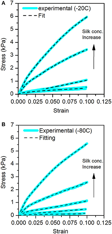
Figure 7. Stress-Strain curves for the different sponge scaffolds obtained from the compression tests. In blue, the experimental data and the fits in the dashed lines. (A) At −20°C and (B) at −80°C.
Table 4 summarizes the bulk, first, second, and third moduli values of the sponge scaffolds (see materials and methods section for model selection). For the sponge scaffolds prepared at −20°C, the bulk modulus varied from 15.6 kPa for 5 mg/ml to 107.3 kPa for 30 mg/ml of silk concentration. For the sponge scaffolds prepared at −80°C, this variation was from 5.4 kPa for 5 mg/ml of silk concentration to 112 kPa for 30 mg/ml.
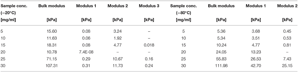
Table 4. Moduli obtained from the fit of the sponge scaffold compression test.
The statistical analysis (Table 5) showed that silk concentration (p = 0.000, F = 60.56) and process temperature (p = 0.01, F = 21.61) had a significant influence on the bulk modulus. When we compared the F-values (i.e., the strength of the effects), we found that the effect of silk concentration was six times stronger than the one of the process temperature. The high R2 and R2 (predicted) from the regression model confirmed the predictability of the bulk modulus with both factors. The “Modulus 1” showed similar significant effects with silk concentration (p = 0.012, F = 14.3) and process temperature (p = 0.01, F = 103.84). Interestingly the process temperature was seven times stronger than the silk concentration. The R2 and R2 predicted were also high. “Modulus 2” showed only a significant effect for silk concentration (p = 0.02, F = 17.43); the R2 predicted was 35.78%, suggesting that the “Modulus 2” effect was probably circumstantial. “Modulus 3” was not analyzed because only a few sponge scaffolds had it.
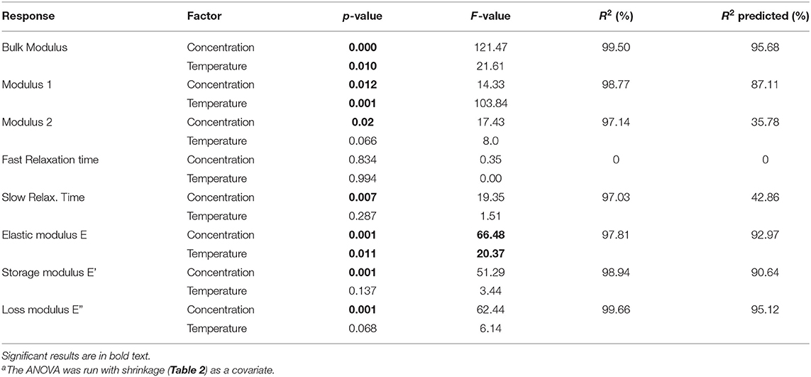
Table 5. ANOVAa and regression analysis of the factorial responses.
The mechanical model consisted of fractional contributions; therefore, an appropriate representation of the effects observed was a plot of the ratio of modulus 1 and 2 by the bulk modulus. Figure 8A illustrates the dependencies of bulk modulus and modulus 1 with silk concentration and temperature. It is important to remember here that the moduli were significantly affected by the two factors, we explained the lack of strong visual evidence by the fact that the shrinkage was a significant covariate for the ANOVA and regression analysis. Modulus 2 was not plotted for clarity (see Figure S9).
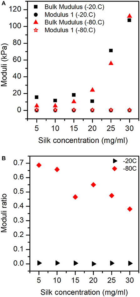
Figure 8. Moduli responses for the sponges in different concentrations of silk and process temperature: (A) Bulk modulus and Modulus 1. (B) Ratio between Modulus 1 and Bulk modulus.
Figure 8B shows the ratio of modulus 1 by the bulk modulus, (i.e., the importance of modulus 1). We observed that for the samples prepared at −20°C, the contribution of modulus 1 was low and constant with silk concentration. Whereas, for the samples prepared at −80°C, we observed a stronger effect of modulus 1 at low silk concentration, monotonously decreasing to weaker effects got modulus 1 at high silk concentration.
Mechanical Properties: Stress Relaxation
For each compression step, we performed a stress-relaxation measurement to evaluate the recovery of the sponge scaffolds. Figure 9 shows the stress-relaxation curves as a function of silk concentration and process temperature. The higher the concentration of silk, the longer it took to relax the materials.
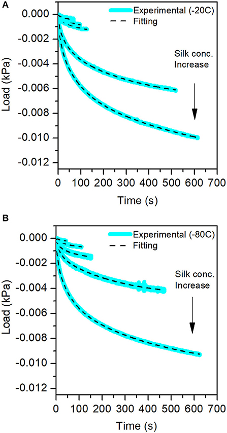
Figure 9. Stress-Relaxation curves obtained from the mechanical test for the different sponge scaffolds. In blue, the experimental data, and in the dash lines, the fits. (A) At −20°C and (B) at −80°C.
The fit of the stress-relaxation yielded three possible relaxation times: a fast relaxation time, an intermediate relaxation time, and a slow relaxation time. Not all samples showed the three relaxations. Table 6 summarizes the numerical values obtained from the fits.
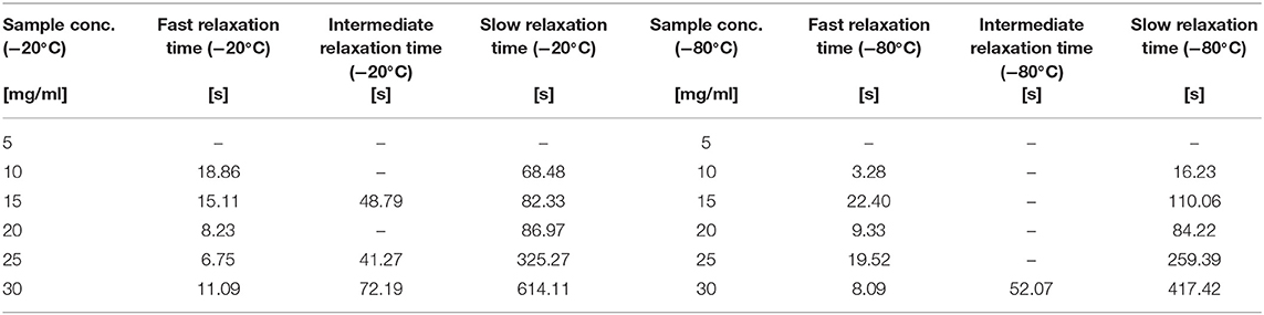
Table 6. Different Relaxation Times for the sponges in different silk concentration and temperatures.
Looking at the statistical analysis (Table 5) we found that only the slow relaxation was significantly affected by silk concentration (p = 0.07, F = 19.35) and not by the process temperature (p = 0.287, F = 1.51). The R2 was high at 97.03%, but the R2 predicted was low at 42.86%, suggesting that the effect was not fully captured by solely the silk concentration. The fast relaxation, on the other hand, was not at all influenced by the design factors.
Figure 10 shows the plot of fast and slow relaxation times.
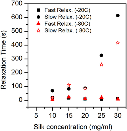
Figure 10. Relaxation Times (Fast mode and Slow mode) for the different sponges. In the ANOVA analysis we found that only the slow relaxation was significantly affected by silk concentration (p-value = 0.07, F-value = 19.35) and not by the process temperature (p-value = 0.287, F-value = 1.51). The fast relaxation was independent of concentration and process temperature.
Mechanical Properties: Dynamic Compression Test
At the end of the stress relaxation step, we applied a 0.5 Hz oscillatory compression of 0.1 mm in amplitude. We extracted from the analysis the elastic modulus (E), the storage modulus (E'), the loss modulus (E”), and the phase (Figure S10). Table 7 summarizes the numerical findings.
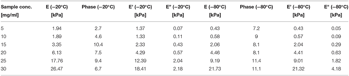
Table 7. Elastic modulus (E), Storage modulus (E') and Loss modulus (E”) obtained for the different sponges from the dynamical mechanical test.
The ANOVA analysis (Table 5) shows that E (p = 0.001, F = 66.48), E' (p = 0.001, F = 0.137), and E” (p = 0.001, F = 62.44) are significantly affected by the silk concentration. Only the elastic modulus was significantly affected by the process temperature (p = 0.01, F = 20.37). When we compared the strength of the effect (F-values), we found that the silk concentration had three times more effective than the process temperature on the elastic modulus. Remarkably, the regression analysis for all three moduli had a high R2 and R2 predicted.
Figure 11A shows the exponential like increase of the elastic modulus (E) as a function of silk concentration and process temperature. Figure 11B illustrates the interplay (phase) between the storage and loss modulus. We found that as a function of silk concentration, the phase increased monotonously for the samples prepared at −80°C. Whereas, for the samples made at −20°C, the phase appeared to rise from low silk concentration and then decreased toward high silk concentration.
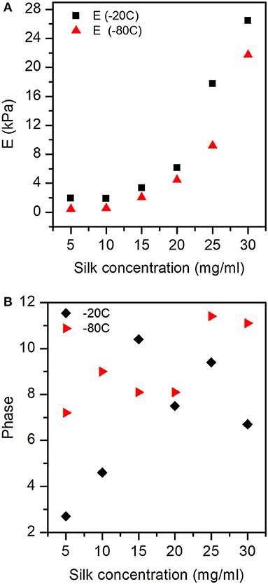
Figure 11. Elastic modulus (E), and Phase obtained for the different sponges from the dynamical compression test. (A) The elastic modulus was significantly affected by both silk concentration and process temperature. (B) The phase shows the interplay between storage and loss modulus with silk concentration and process temperature. See Figure S4 for the exact values of E, E', and E” at −20 and −80°C.
Discussion
Macroscopic Organization
We prepared RSF sponge scaffolds by ice templating with six different concentrations of silk and two different freezing temperatures. A surprising result of the sample preparation was that the scaffolds exhibited shrinkage. Therefore, the scaffolds used for tomography analysis were chosen based on a visual inspection where the most homogeneous and representative scaffolds were analyzed. The resolution of the images was sufficient to perform the porosity and tortuosity calculations.
The result showed a significant relationship between the concentration of the silk solution and the porosity. This relation was somewhat expected, as the higher the protein concentration, the more material, and the less void space. This behavior has also been observed with other materials (Wegst et al., 2010) and in silks (Min et al., 2009; Zhu et al., 2014; Kadakia et al., 2016). We also found that the process temperature had an impact on the porosity (p = 0.043). Other studies have also shown that freezing temperature had an effect on the pore size (O'Brien et al., 2007) and could be the reason for the increased permeability. However, porosity is not sufficient. Now using tomography and image processing, we were able to estimate the sponge scaffolds tortuosity, the path taken by the fluid. The silk concentration had significant effects, but the processed temperature was significant only for the tortuosity in the XY plane (normal to the syringe axis). We interpreted this anisotropy by the fact that the freezing of the samples most likely happened laterally (side of the syringe) from outside to inside, thus not affecting the tortuosity in the z-direction. We also noted that the tortuosity values were very close to 1, (i.e., a direct flow path). Those values should further be scrutinized. Indeed, any calculation depended on the thresholding and binarization processes. In our case, the poor contrast (Figure 3) may have yielded a less than optimal binarized image. Nevertheless, the changes within the sample should still be valid. For example, when combing the tortuosity (λ) and porosity (ε) using , the hindrance factor. We found that the hindrance was higher in the Z-direction compared to the XY-plane. The effect appeared to be driven by the geometry and design of the surfaces exposed to the freezing planes (Panda et al., 2017).
The ice nucleation was critical when frozen at −20°C, the ice nucleation takes place slower than it does when frozen at −80°C, due to the temperature being very close to the glass transition temperature of the water-silk proteins between −20 and −80°C (Guan et al., 2016), and estimated at −62°C in fibers (Guan et al., 2016); thus allowing ice crystals to grow larger and create larger voids in the sponge scaffolds. At −80°C, the pore sizes were no longer affected by the water-silk glass transition. Nazarov et al. (2004) already observed this decorrelation. With our current tomography data, and the correlation length analysis we confirmed Nazarov et al. findings and showed specifically that temperature and concentration affected only the large pores (see Figure 4C). No conclusion could be drawn about their connectivity and distribution.
Nevertheless, looking at the permeability of some tissues, for example, cartilage permeability ranges from 0.1 × 10⁻¹⁸ to 2 × 10⁻¹⁸ m2 and ~ 10−9 m2 for trabecular bone (O'Brien et al., 2007). We found that the silk sponge scaffolds permeability was far from the cartilage and neared to the trabecular bone. A higher concentration of silk would not be sufficient to mimic tissue permeability. Still, the control of porosity and tortuosity to insure that the hindrance is kept low (i.e., optimal transport properties).
Mechanical Response
Collectively we found higher bulk moduli and longer relaxation times with increasing silk concentration. Here we tentatively linked the re-organization of the amorphous domains yielding more hydrophobic pockets to slower relaxation. Interestingly, only the slow relaxation time variation was statistically influenced by silk concentration. We further interpreted the slow relaxation with the transport of fluid in the silk sponge scaffolds. We tentatively associated the fast relaxation with a viscoelastic relaxation, which was not influenced by the silk concentration and process temperatures. We interpreted this counter-intuitive observation by the fact that we probed the silk sponges in the small strains regime, and at slow strain rates (i.e., conditions at which the faster viscoelastic relaxation would have already taken place). Panda et al. noted that the sponge scaffolds relaxations curves were characteristic of a viscoelastic solid, and although being a biphasic system, behaved almost like a Newtonian fluid, and relaxing almost instantaneously (Panda et al., 2017).
The interplay of the bulk and modulus 1 provided new insights to explain the transport (slow relaxation) and possible failures of the materials. The mechanical model consisted of fractional contributions from “failure events.” The bulk modulus captured the elastic contribution and was controlled predominantly by the silk concentration. We tentatively associated modulus 1 to the collapse of the pores structures and were controlled mostly by the process temperature. At −20°C, the fractional contribution of modulus 1 was low and independent of silk concentration (Figure 8B), suggesting the existence of critical pore size and connectivity above which the sponge scaffolds responses appeared elastic. At −80°C, on the other hand, we observed a dependence of the fractional contribution of modulus 1 with silk concentration (Figure 8B). The increase of the fractional amount of modulus 1 suggested more collapsible pores, thus a compromised mechanics and transport.
Figure 12 illustrates the three correlation lengths (ξ1, 2, 3) found from the tomography analysis, and the collapse of the larger pore networks (ξ3). Dynamically, we found unremarkably that the elastic modulus (E) was predominantly dependent on the concentration of silk. Interestingly, when we looked at the interplay between the storage (E') and loss moduli (E”), we found no cross-over (Figure S4). We discovered that E' was systematically higher than E”, and the difference was more pronounced at higher silk concentrations. By analogy with the rheology, the silk sponge scaffolds behaved like an elastic solid, although not an ideal one because some of the mechanical energy was dissipated. Looking at the phase (Figure 11B), we found that at −80°C the phase increased monotonously with silk concentration. The linear dependence of the phase with silk concentration suggested that at −80°C, the sponge scaffolds were more and more viscous. Paradoxically, since we observed no cross-over between E' and E” we proposed that the effect stemmed from a strong coupling between the matrix and the fluid present. At −20°C, we observed an increase followed by a decrease in the phase. The change indicated a more viscous silk sponge scaffold at low concentrations of silk and a more elastic silk sponge scaffold at higher silk concentrations. The effect was most likely related to the marked decrease of the larger pores as seen in Figure 4C. A better understanding of the fluid coupling and transport is needed, however, to resolve the dynamics of the sponge scaffolds.
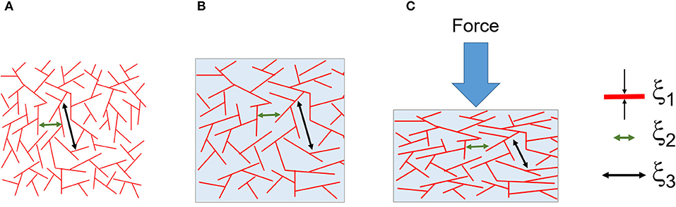
Figure 12. Composite illustration of the results from the tomographic analysis and mechanics. (A) The dry foam with a distribution of three correlation lengths ξ1, ξ2, and ξ3. The correlation lengths were assigned to the silk thickness (at around 4 μm), the small pores (between 10 and 20 μm) and the large pores (between 50 and 130 μm), respectively. (B) The wet and swollen scaffold. (C) The compressed scaffold and the collapse of the larger pores (ξ3).
Molecular Origin of Scaffold Morphology and Mechanical Response
The results from the FTIR analysis indicated that the silk structure had been affected by the manufacturing process, revealed by the amide I/II ratio, which exhibited a significant dependence on concentration. By further analyzing the crystallinity index (specific to rigid domains) and tyrosine ratio (specific to amorphous domains), we found that the crystalline/rigid domains of the silk stayed intact during the manufacturing. Instead, the amorphous domains changed significantly. We interpreted the organization of the amorphous domains with concentration, as re-orientation toward more hydrophobic interfaces (ratio changed from about 1.1 to 0.9). Others have described the network structure of silk scaffolds as heterogeneous with β-sheet and fibrillar structures (Numata et al., 2011). The interpretation, however, does not translate into mechanical effects. Recently two approaches to explain protein-based materials mechanics from its structural organization and thermodynamics have been put forward (Puglisi et al., 2017) and (Panda et al., 2018). Still the roles of the silk secondary structures, their organization and the strong fluid coupling to the mechanics remain unclear. On-going work combining mechanical deformation with spectroscopy and scattering might reveal the underlying mechanisms.
Summary
We used a factorial design analysis to decouple the effects of silk concentration and freezing temperature (for cryogel formation). In summary
• We found that the scaffolds suffered from shrinkage upon freeze drying. Although not controlled, the effect was included in the ANOVA analysis of the subsequent responses
• We derived three correlation lengths (ξ) that we assigned to the silk thickness (around 4 μm), small pores (between 10 and 20 μm) and large pores (50 and 130 μm). Interestingly only ξ3 decreased at −20°C with increasing silk concentration
• The permeability, porosity, and tortuosity were high, and mostly dependent on the silk concentration for the last two. In contrast for the permeability, the silk concentration and temperature had a similar effect
• Structurally, by FTIR, the silk proteins amorphous organization only was affected by the protein concentration and process temperature. The β-sheet structures were not affected
• Mechanically, using a fracture model, the scaffolds were dominated by the collapse of the larger pores
• We considered the scaffolds as biphasic (silk and aqueous solvent) material. We assigned the slow stress relaxation to the fluid displacement, and the fast stress relaxation to a coupled viscoelastic response from the silk-fluid
• Dynamically, the scaffolds behaved as viscoelastic solids with a strong dependence on silk concentration for the −20°C process temperature. We tentatively explained the effect from the larger pores sizes more affected at −20°C than at −80°C.
Conclusion
Overall, our results are in line with previous studies (Nazarov et al., 2004; Panda et al., 2017; Ribeiro et al., 2019). Our use of the tomography, mechanical test, and detailed statistical analysis provides inroads into the interplay between process parameters (silk concentration and process temperature) and the multiple responses of the silk sponge scaffolds. The development of a new mechanical fitting for the compression test helped capture simply the different failure modes in the sponge scaffolds as well as correlates those events to relaxation and eventually transport properties. We could link the macroscopic responses to specific pore sizes distribution in the scaffolds. We are further investigating the advantages of our progressive acidification method as well as improving the tomography characterization with in-situ characterization.
Data Availability Statement
The datasets generated for this study are available on request to the corresponding author.
Author Contributions
CD, BF, NA, EA, and SH contributed conception and design of the study. BF, NA, EA, and JE collected the data. CD performed the data analysis. NA, EA, and BF wrote the first draft of the manuscript. BF, NA, EA, JE, SH, and CD wrote sections of the manuscript. All authors contributed to manuscript revision, read, and approved the submitted version.
Funding
The Olle Engkvist Foundation (Stiftelsen Olle Engkvist Byggmastare grant number 189–0280) and the Crafoord Foundation (Crafoordska Stiftelsen grant number 20180927) are kindly acknowledged for their financial support. The Lund Institute for Advanced Neutron and X-ray Science (LINXS) is recognized for partial funding.
Conflict of Interest
The authors declare that the research was conducted in the absence of any commercial or financial relationships that could be construed as a potential conflict of interest.
Acknowledgments
X-ray tomography was performed at the 4D Imaging Lab at Lund University.
Supplementary Material
The Supplementary Material for this article can be found online at: https://www.frontiersin.org/articles/10.3389/fmats.2020.00211/full#supplementary-material
References
Ak, F., Oztoprak, Z., Karakutuk, I., and Okay, O. (2013). Macroporous silk fibroin cryogels. Biomacromolecules 14, 719–727. doi: 10.1021/bm3018033
Bhat, N. V., and Nadiger, G. S. (1980). Crystallinity in silk fibers: partial acid hydrolysis and related studies. J. Supercrit. Fluids 25, 921–932. doi: 10.1002/app.1980.070250518
Blaise, A., Baravian, C., André, S., Dillet, J., Michot, L. J., and Mokso, R. (2010). Investigation of the mesostructure of a mechanically deformed HDPE by synchrotron microtomography. Macromolecules 43, 8143–8152. doi: 10.1021/ma101033b
Boulet-Audet, M., Vollrath, F., and Holland, C. (2015). Identification and classification of silks using infrared spectroscopy. J. Exp. Biol. 218, 3138–3149. doi: 10.1242/jeb.128306
Caccavo, D., Cascone, S., Lamberti, G., and Barba, A. A. (2018). Hydrogels: experimental characterization and mathematical modelling of their mechanical and diffusive behaviour. Chem. Soc. Rev. 47, 2357–2373. doi: 10.1039/C7CS00638A
Chen, F., Porter, D., and Vollrath, F. (2010). Silkworm cocoons inspire models for random fiber and particulate composites. Phys. Rev. E Stat. Nonlin. Soft Matter Phys. 82:041911. doi: 10.1103/PhysRevE.82.041911
Cho, S. Y., Heo, S., and Jin, H. J. (2012). Controlling microstructure of three-dimensional scaffolds from regenerated silk fibroin by adjusting pH. J. Nanosci. Nanotechnol. 12, 806–810. doi: 10.1166/jnn.2012.5364
Cooper, S. J., Bertei, A., Shearing, P. R., Kilner, J. A., and Brandon, N. P. (2016). TauFactor: an open-source application for calculating tortuosity factors from tomographic data. SoftwareX 5, 203–210. doi: 10.1016/j.softx.2016.09.002
DeBari, M. K., and Abbott, R. D. (2019). Microscopic considerations for optimizing silk biomaterials. Wiley Interdiscip. Rev. Nanomed. Nanobiotechnol. 11:e1534. doi: 10.1002/wnan.1534
Del Giudice, A., Dicko, C., Galantini, L., and Pavel, N. V. (2017). Time-dependent pH scanning of the acid-induced unfolding of human serum albumin reveals stabilization of the native form by palmitic acid binding. J. Phys. Chem. B 121, 4388–4399. doi: 10.1021/acs.jpcb.7b01342
Deville, S. (2013). Ice-templating, freeze casting: beyond materials processing. J. Mater. Res. 28, 2202–2219. doi: 10.1557/jmr.2013.105
Deville, S., Saiz, E., Nalla, R. K., and Tomsia, A. P. (2006). Freezing as a path to build complex composites. Science 311, 515–518. doi: 10.1126/science.1120937
Elahi, M. F., Wang, F., Li, Y., and Wang, L. (2017). “Porous structures from biobased synthetic polymers via freeze-drying,” in Porous Lightweight Composites Reinforced with Fibrous Structures, eds Y. Yang, J. Yu, H. Xu, and B. Sun (Berlin; Heidelberg: Springer), 179–206. doi: 10.1007/978-3-662-53804-3_8
Epstein, N. (1989). On tortuosity and the tortuosity factor in flow and diffusion through porous media. Chem. Eng. Sci. 44, 779–781. doi: 10.1016/0009-2509(89)85053-5
Griffith, L. G., and Naughton, G. (2002). Tissue engineering–current challenges and expanding opportunities. Science 295, 1009–1014. doi: 10.1126/science.1069210
Griffon, D. J., Sedighi, M. R., Schaeffer, D. V., Eurell, J. A., and Johnson, A. L. (2006). Chitosan scaffolds: Interconnective pore size and cartilage engineering. Acta Biomater. 2, 313–320. doi: 10.1016/j.actbio.2005.12.007
Guan, J., Wang, Y., Mortimer, B., Holland, C., Shao, Z., Porter, D., et al. (2016). Glass transitions in native silk fibres studied by dynamic mechanical thermal analysis. Soft Matter 12, 5926–5936. doi: 10.1039/C6SM00019C
Holland, C., Numata, K., Rnjak-Kovacina, J., and Seib, F. P. (2019). The biomedical use of silk: past, present, future. Adv. Healthcare Mater. 8:e1800465. doi: 10.1002/adhm.201800465
Horrocks, N. P. C., Vollrath, F., and Dicko, C. (2013). The silkmoth cocoon as humidity trap and waterproof barrier. Comp. Biochem. Physiol. A Mol. Integr. Physiol. 164, 645–652. doi: 10.1016/j.cbpa.2013.01.023
Howard, D., Buttery, L. D., Shakesheff, K. M., and Roberts, S. J. (2008). Tissue engineering: strategies, stem cells and scaffolds. J. Anat. 213, 66–72. doi: 10.1111/j.1469-7580.2008.00878.x
Ishida, K. P., and Griffiths, P. R. (1993). Comparison of the amide I/II intensity ratio of solution and solid-state proteins samples by transmission, attenuated total reflectance, and diffuse reflectance spectrometry. Appl. Spectrosc. 47, 584–589. doi: 10.1366/0003702934067306
Kadakia, P. U., Jain, E., Hixon, K. R., Eberlin, C. T., and Sell, S. A. (2016). Sonication induced silk fibroin cryogels for tissue engineering applications. Mater. Res. Express 3:055401. doi: 10.1088/2053-1591/3/5/055401
Kolahreez, D., and Morshed, M. (2018). Fabrication of porous three-dimensional fibroin structures through a freezing process. J. Appl. Polymer Sci. 135:46537. doi: 10.1002/app.46537
Langer, R., and Vacanti, J. (2016). Advances in tissue engineering. J. Pediatr. Surg. 51, 8–12. doi: 10.1016/j.jpedsurg.2015.10.022
Lovett, M., Lee, K., Edwards, A., and Kaplan, D. L. (2009). Vascularization strategies for tissue engineering. Tissue Eng. B Rev. 15, 353–370. doi: 10.1089/ten.teb.2009.0085
Makaya, K., Terada, S., Ohgo, K., and Asakura, T. (2009). Comparative study of silk fibroin porous scaffolds derived from salt/water and sucrose/hexafluoroisopropanol in cartilage formation. J. Biosci. Bioeng. 108, 68–75. doi: 10.1016/j.jbiosc.2009.02.015
Mallepally, R. R., Marin, M. A., Surampudi, V., Subia, B., Rao, R. R., Kundu, S. C., et al. (2015). Silk fibroin aerogels: potential scaffolds for tissue engineering applications. Biomed. Mater. 10:035002. doi: 10.1088/1748-6041/10/3/035002
Maniglio, D., Bonani, W., Migliaresi, C., and Motta, A. (2018). Silk fibroin porous scaffolds by N2O foaming. J. Biomater. Sci. Polymer Edn. 29, 491–506. doi: 10.1080/09205063.2018.1423811
Meghezi, S., Drouin, B., and Mantovani, D. (2017). “Collagen hydrogel-based scaffolds for vascular tissue regeneration: Mechanical and viscoelastic characterization,” in Characterization of Polymeric Biomaterials, eds. M.C. Tanzi and S. Farè (Woodhead Publishing).
Meinel, L., Hofmann, S., Karageorgiou, V., Kirker-Head, C., McCool, J., Gronowicz, G., et al. (2005). The inflammatory responses to silk films in vitro and in vivo. Biomaterials 26, 147–155. doi: 10.1016/j.biomaterials.2004.02.047
Min, S., Gao, X., Liu, L., Tian, L., Zhu, L., Zhang, H., et al. (2009). Fabrication and characterization of porous tubular silk fibroin scaffolds. J. Biomater. Sci. Polym. Edn. 20, 1961–1974. doi: 10.1163/156856208X396056
Ming, J., Li, M., Han, Y., Chen, Y., Li, H., Zuo, B., et al. (2016). Novel two-step method to form silk fibroin fibrous hydrogel. Mater. Sci. Eng. C 59, 185–192. doi: 10.1016/j.msec.2015.10.013
Monti, P., Freddi, G., Bertoluzza, A., Kasai, N., and Tsukada, M. (1998). Raman spectroscopic studies of silk fibroin from bombyx mori. J. Raman Spectrosc. 29, 297–304. doi: 10.1002/(SICI)1097-4555(199804)29:4<297::AID-JRS240>3.0.CO;2-G
Moreira, E. A., and Coury, J. R. (2004). The influence of structural parameters on the permeability of ceramic foams. Braz. J. Chem. Eng. 21, 23–33. doi: 10.1590/S0104-66322004000100004
Nazarov, R., Jin, H. J., and Kaplan, D. L. (2004). Porous 3-D scaffolds from regenerated silk fibroin. Biomacromolecules 5, 718–726. doi: 10.1021/bm034327e
Numata, K., Katashima, T., and Sakai, T. (2011). State of water, molecular structure, and cytotoxicity of silk hydrogels. Biomacromolecules 12, 2137–2144. doi: 10.1021/bm200221u
O'Brien, F. J. (2011). Biomaterials and scaffolds for tissue engineering. Mater. Today 14, 88–95. doi: 10.1016/S1369-7021(11)70058-X
O'Brien, F. J., Harley, B. A., Waller, M. A., Yannas, I. V., Gibson, L. J., and Prendergast, P. J. (2007). The effect of pore size on permeability and cell attachment in collagen scaffolds for tissue engineering. Technol. Health Care 15, 3–17. doi: 10.3233/THC-2007-15102
Okay, O., and Lozinsky, V. I. (2014). Synthesis and structure–property relationships of cryogels. Adv. Polym. Sci. 263, 103–157. doi: 10.1007/978-3-319-05846-7_3
Panda, D., Konar, S., Bajpai, S. K., and Arockiarajan, A. (2017). Synthesis and viscoelastic characterization of microstructurally aligned Silk fibroin sponges. J. Mech. Behav. Biomed. 71, 362–371. doi: 10.1016/j.jmbbm.2017.03.029
Panda, D., Konar, S., Bajpai, S. K., and Arockiarajan, A. (2018). Thermodynamically-consistent constitutive modeling of aligned Silk fibroin sponges: theory and application to uniaxial compression. Int. J. Solids Struct. 138, 144–154. doi: 10.1016/j.ijsolstr.2018.01.006
Pennella, F., Cerino, G., Massai, D., Gallo, D., Falvo D'Urso Labate, G., Schiavi, A., et al. (2013). A survey of methods for the evaluation of tissue engineering scaffold permeability. Ann. Biomed. Eng. 41, 2027–2041. doi: 10.1007/s10439-013-0815-5
Puglisi, G., De Tommasi, D., Pantano, M. F., Pugno, N. M., and Saccomandi, G. (2017). Micromechanical model for protein materials: from macromolecules to macroscopic fibers. Phys. Rev. E 96:042407. doi: 10.1103/PhysRevE.96.042407
Qi, Y., Wang, H., Wei, K., Yang, Y., Zheng, R. Y., Kim, I. S., et al. (2017). A review of structure construction of silk fibroin biomaterials from single structures to multi-level structures. Int. J. Mol. Sci. 18:237. doi: 10.3390/ijms18030237
Rajkhowa, R., Gil, E. S., Kluge, J., Numata, K., Wang, L., Wang, X., et al. (2010). Reinforcing silk scaffolds with silk particles. Macromol. Biosci. 10, 599–611. doi: 10.1002/mabi.200900358
Reis, R. L., Neves, N. M., Mano, J. F., Gomes, M. E., Marques, A. P., and Azevedo, H. S. (2008). Natural-Based Polymers for Biomedical Applications. Woodhead Publishing.
Ribeiro, V. P., da Silva Morais, A., Maia, F. R., Canadas, R. F., Costa, J. B., Oliveira, A. L., et al. (2018). Combinatory approach for developing silk fibroin scaffolds for cartilage regeneration. Acta Biomater. 72, 167–181. doi: 10.1016/j.actbio.2018.03.047
Ribeiro, V. P., Pina, S., Costa, J. B., Cengiz, I. F., García-Fernández, L., Fernández-Gutiérrez, M. D. M., et al. (2019). Enzymatically cross-linked silk fibroin-based hierarchical scaffolds for osteochondral regeneration. ACS Appl. Mater. Interf. 11, 3781–3799. doi: 10.1021/acsami.8b21259
Rockwood, D. N., Preda, R. C., Yücel, T., Wang, X., Lovett, M. L., and Kaplan, D. L. (2011). Materials fabrication from Bombyx mori silk fibroin. Nat. Protoc. 6, 1612–1631. doi: 10.1038/nprot.2011.379
Schindelin, J., Arganda-Carreras, I., Frise, E., Kaynig, V., Longair, M., Pietzsch, T., et al. (2012). Fiji: an open-source platform for biological-image analysis. Nat. Methods 9, 676–676. doi: 10.1038/nmeth.2019
Tamada, Y. (2005). New process to form a silk fibroin porous 3-D structure. Biomacromolecules 6, 3100–3106. doi: 10.1021/bm050431f
Varley, M. C., Neelakantan, S., Clyne, T. W., Dean, J., Brooks, R. A., and Markaki, A. E. (2016). Cell structure, stiffness and permeability of freeze-dried collagen scaffolds in dry and hydrated states. Acta Biomater. 33, 166–175. doi: 10.1016/j.actbio.2016.01.041
Vepari, C., and Kaplan, D. L. (2007). Silk as a biomaterial. Prog. Polym. Sci. 32, 991–1007. doi: 10.1016/j.progpolymsci.2007.05.013
Wegst, U. G. K., Schecter, M., Donius, A. E., and Hunger, P. M. (2010). Biomaterials by freeze casting. Philos. Trans. Royal Soc. A 368, 2099–2121. doi: 10.1098/rsta.2010.0014
Yang, S., Leong, K.-F. E., Du, Z. M. E., and Chua, C.-K. (2001). The design of scaffolds for use in tissue engineering. Part I. traditional factors. Tissue Eng. 7, 679–689. doi: 10.1089/107632701753337645
Zhang, W., Wray, L. S., Rnjak-Kovacina, J., Xu, L., Zou, D., Wang, S., et al. (2015). Vascularization of hollow channel-modified porous silk scaffolds with endothelial cells for tissue regeneration. Biomaterials 56, 68–77. doi: 10.1016/j.biomaterials.2015.03.053
Keywords: micro-CT, porous silk scaffolds, ice templating, progressive acidification, compression, stress relaxation, dynamic compression
Citation: Ferreira BMP, Andersson N, Atterling E, Engqvist J, Hall S and Dicko C (2020) 3D Structure and Mechanics of Silk Sponge Scaffolds Is Governed by Larger Pore Sizes. Front. Mater. 7:211. doi: 10.3389/fmats.2020.00211
Received: 21 October 2019; Accepted: 09 June 2020;
Published: 17 July 2020.
Edited by:
Nicola Maria Pugno, University of Trento, ItalyReviewed by:
Domenico De Tommasi, Politecnico di Bari, ItalyShangchao Lin, Shanghai Jiao Tong University, China
Copyright © 2020 Ferreira, Andersson, Atterling, Engqvist, Hall and Dicko. This is an open-access article distributed under the terms of the Creative Commons Attribution License (CC BY). The use, distribution or reproduction in other forums is permitted, provided the original author(s) and the copyright owner(s) are credited and that the original publication in this journal is cited, in accordance with accepted academic practice. No use, distribution or reproduction is permitted which does not comply with these terms.
*Correspondence: Cedric Dicko, Y2VkcmljLmRpY2tvQHRiaW9rZW0ubHRoLnNl