Abstract
Supercapacitors (SCs) are energy storage devices that bridge the gap between batteries and conventional capacitors. They can store more energy than capacitors and supply it at higher power outputs than batteries. These features, combined with high cyclability and long-term stability, make SCs attractive devices for energy storage. SCs are already present in many applications, either in combination with other energy storage devices (mainly batteries), or as autonomous energy sources. Porous carbons are presently used in the electrodes of commercial SCs due to their high surface area and their good conductivity. However, new porous materials are continuously being developed. Herein, an outline of the principles of the energy storage mechanism in SCs is presented as a guide to illustrate the research on porous carbons materials for SC applications. Indeed, an overview of these carbons and their synthesis methods is also presented. In the context of an urgent need to progress toward the development of environmentally friendly technologies and methods, the final part of this review focuses on the studies carried out using biosourced carbon precursors, such as tannins, which are natural polyphenolic molecules. In particular, mimosa tannin-derived carbon materials with controlled micro- and mesoporosity can be produced by methods with lower environmental impact and lower health and safety risks because crosslinkers are not needed to produce resins.
Introduction
World's electricity consumption has increased significantly in recent decades, from ~11,000 TWh in 1990 to ~23,000 TWh in 2016, according to the International Energy Agency (IEA), and there is still a strong dependence on fossil fuels such as coal, oil and gas as energy sources (IEA, 2019). Furthermore, it is generally agreed that the increasing concentration of greenhouse gases in the atmosphere from the 1950s is partly attributable to the burning of fossil fuels, which is causing global climate change (Pachauri et al., 2015). The limits of fossil fuels reserves and the increasing global warming have amplified awareness on the need to phase out the fossil fuel industry. The transition to energy production from renewable sources and environmentally friendly technologies is a public demand. This poses a challenge for the production of electricity based on fluctuating energy sources such as solar or wind, among others. Thus, research aiming to improve the performance of energy storage devices is of great relevance nowadays.
The role of energy storage devices in the electrical system is to collect excess of energy during high production peaks and act as a reservoir, releasing energy when required. Figure 1A lists some of the different storage technologies used at different steps of the electrical system (IEA, 2014; Aneke and Wang, 2016). Pumped-storage hydropower and compressed air energy storage are widely used in electric power plants for large-scale production. On the other hand, batteries are suitable for a wider range of mid- and short-term storage applications such as distribution to remote sites, electric vehicles, small-scale production and off-grid storage for houses or buildings, and portable electronic devices also rely on battery use. On the contrary, supercapacitors (SCs) are high-power devices, meaning that they can supply stored energy at fast rates, and they are mostly used in short-term applications where bursts of electricity are needed.
Figure 1
SCs are presently used in a variety of applications, which could be further developed as stand-alone energy suppliers if their energy densities were increased (Sharma and Bhatti, 2010; Aneke and Wang, 2016; González et al., 2016; Wang et al., 2016). Accordingly, the international community has established the pursuit of improving the SCs performances as one of the short-term actions in the context of research and development on energy storage (IEA, 2014). This review is not intended to be exhaustive but to present a global vision of the principles underlying the energy storage mechanism in SCs, and to explain how these principles have guided the research of materials in this field, in particular for the production of carbon electrodes. Given the environmental issues mentioned above, the last part of this review incorporates studies using non-toxic and environmentally friendly carbon precursors, such as tannin extracts, to produce carbon electrodes for SCs.
Supercapacitors
Basic Principles
A SC consists of two parallel electrodes separated by a non-conductive material impregnated with an electrolyte, as illustrated in Figure 1B. By applying a potential between the electrodes, the ions in the electrolyte are attracted to the electrode of opposite charge. Derived from charge accumulation and the interaction with the electrode surface, an electrostatic double-layer (EDL) is created on each electrode (González et al., 2016). Hence, there are two contributions to the total capacitance of the device, represented by the two capacitors in series shown in the simplified electric circuit of Figure 1B. An equivalent series resistance (ESR) is added to the circuit to account for the resistance of all the components of the device (Xie et al., 2018). The EDL generation process is ideally reversible, resulting in fast responses for charge and discharge, which result in high power in SCs. In addition, high cyclability, i.e., retention of capacitance after repetitive cycles of charge and discharge, and long lifetimes are achieved due to the low degradation of components derived from the reversibility of the EDL formation process.
From a macroscopic point of view, the capacitance C of a SC can be calculated as in a regular capacitor of parallel plates:
where ε0 is the permittivity of vacuum, ε is the permittivity of the electrolyte, A is the area of the electrode, and d is the effective thickness of the EDL. The energy, E, of a capacitor is calculated as follows:
where V is the applied voltage to the device, also called potential window. For an ideal EDL SC, C is not a function of V and Equation (2) becomes:
The power, P, is then calculated through:
where tdis is the discharge time. Figure 2 shows a Ragone plot of typical values of energy and power of SCs compared to those of other energy storage devices such as batteries, fuel cells and capacitors.
Figure 2
Applications
The characteristic E and P-values of SCs bridge the gap between conventional capacitors and batteries, as shown in Figure 2. Hence, SCs find their applications either as autonomous energy sources or in combination with other devices, as detailed below (Kötz and Carlen, 2000; Miller and Burke, 2008; Conte, 2010; Sharma and Bhatti, 2010; Gu and Yushin, 2014; Aneke and Wang, 2016; González et al., 2016; Gautham Prasad et al., 2019; IOXUS Inc, 2020; Maxwell Technologies Inc., 2020):
Memory back-ups. Fast-response SCs are a short-term solution to a brief interruption of power supply to the memory.
Portable tools. SCs are used as an energy source in camera flashes or portable screwdrivers, since only bursts of energy are required along with rapid and constant recharging.
Distribution and storage of electrical energy. SCs are able to compensate short-duration voltage fluctuations in the distribution line and to match the variations between production and consumption. In addition, SCs are used to restart collapsed power systems or to supply energy until the primary source is restored. SCs are also used as storage devices in renewable energy production plants, especially in wind power applications, as they require little maintenance.
Decoupling of power and energy needs. SCs are used to meet the power needs while the principal source of energy is provided by a different system. This type of decoupling is found in hybrid and electric vehicles.
Regeneration devices. The energy released by machines with repetitive and constant movements can be recovered by SCs. Thus, SCs are found, for example, in cranes and elevators or in the braking systems of hybrid or electric vehicles like buses, delivery or garbage trucks and trains.
One of the main disadvantages of SCs compared to batteries is that they store less energy, which limits their use as autonomous devices. It is clear from Equation (3) that there are two ways to overcome this drawback: widening the potential window or increasing the capacitance. The former is strongly associated with the choice of electrolyte and the latter with the properties of the electrode. Nevertheless, they are intimately related to each other, because there must be a synergy between all the components of the SC. A clear example of this synergy is the pseudocapacitive behavior that some materials present when used as electrodes, where rapid Faradaic (redox) reactions occur on or near the surface of the electrode. The presence of redox reactions depends on the properties of the electrode material and on the affinity of the electrolyte toward it. SC devices with electrodes made of materials in which both EDL and pseudocapacitance storage mechanisms are present are also referred to as pseudocapacitors (PSCs) and could reach even higher values of capacitance. However, the increased capacitance in PSCs may be accompanied by a loss of power and long-term stability compared to that of SCs (González et al., 2016).
New materials are constantly being developed and their performance as electrodes for SCs must be evaluated. In the following section, the electrochemical testing techniques commonly used on a laboratory scale are briefly described in order to illustrate the expected behavior of a SC. Next, the types and general characteristics of commonly used electrolytes and the advances in the research for porous materials as electrodes for SCs are discussed.
Electrochemical Testing Techniques
Cell Configuration
Figure 3 shows schemes of cell configurations normally used for SC testing. The three-electrode cells (Figure 3A) are useful for estimating the contributions of pseudocapacitance or for better understanding the more fundamental behavior of materials, while the two-electrode cells (Figure 3B) are used to evaluate the performance of materials in operating conditions closer to those of real SC devices (Xie et al., 2018). T-type cells are a combination of two- and three-electrode cell configurations (Figure 3C), which allow studying the performance of each electrode in a SC along with the performance of the whole system operating at the equilibrium potential of both electrodes (Sevilla et al., 2019). Thus, a three-electrode configuration measures the performance of a single electrode (the working electrode in Figure 3A), whereas a two-electrode configuration evaluates the performance of two electrodes as a system (the cell). As shown in Figure 1B, in a symmetric SC, the two electrodes are made of the same material and, based on the associated simplified circuit, its capacitance, C, can be calculated assuming that the contribution of each electrode is identical, i.e., Ce1 = Ce2 = Ce. Therefore:
Reporting normalized values of capacitance allows for the comparison of results from different studies. Thus, from Equation (6) and considering that the normalization factor of the cell is twice the normalization factor of an electrode, i.e., N = 2Ne (Zuliani et al., 2015):
N is generally chosen to be either the mass or the volume of the electrodes. For simplicity, from now on, C and Ce will refer to the capacitances normalized by the mass of the electrode(s), called specific cell capacitance and specific electrode capacitance, respectively.
Figure 3
Many of the materials that can be used as electrodes for SCs are in powder form, so it is necessary to use a binder to agglomerate the powder particles and create a paste, or slurry, from which the electrodes are obtained. Some additives can also be mixed with the active material to improve their electrical conductivity. A correct assessment of the materials performance requires giving the calculations of normalized capacitance as a function of the total mass or the total volume of the electrode, i.e., including binder and/or the additives.
Cyclic Voltammetry (CV)
During cyclic voltammetry (CV) tests, a potential (V) is applied and increased at constant rate over time (scan rate) while the current response, I, is measured. An ideal SC would exhibit a rectangular curve when I is plotted as a function of V, see Figure 4A. During charging, the sharp increase in I at the beginning of the cycle is due to the rapid formation of the EDL and it remains constant when V increases because no Faradaic reaction occurs. Given the reversible nature of the EDL formation mechanism, the CV curve during discharge obtained when V decreases is the exact inverse of the charging curve. Evidently, the CV curves of the real SCs deviate from the ideal one, and those of PSCs also display I peaks due to the generation of charge by redox reactions, as shown in Figure 4A. In addition, widening the potential window in CV measurements allows identifying the point at which decomposition of the electrolyte occurs, manifesting by an I peak at each edge of the CV curve. Then, this information can be used to set the operating voltage of a SC cell. From CV data, C is calculated by:
where the numerator is the area delimited by the CV curve, s is the scan rate, V is the potential window and m is the sum of the masses of the two electrodes in the cell. If a three-electrode configuration is used, Ce can be calculated by substituting m in Equation (8) for the mass of the working electrode, me.
Figure 4
Galvanostatic Charge-Discharge (GCD)
In the galvanostatic charge-discharge (GCD) technique, a constant I is applied to the system while the response V is recorded as a function of time. The method is normally carried out with a two-electrode configuration. In an ideal SC, charge and discharge have a linear mirror behavior, resulting in triangular curves. In real SCs and PSCs, the curves deviate from the linear behavior, see Figure 4B. Any device will exhibit a sudden drop in potential during the transition from charge to discharge. This is called IR drop and it is directly associated with the ESR of the device. From GCD data, C is calculated by:
where I is the constant current applied, ΔV/Δt is the slope of the discharge curve and m is the sum of the masses of the two electrodes in the SC. Ce can then be approximated using Equation (7). Using this value of C, those of E and P of the SC can be calculated directly from Equations (3) and (4), respectively, keeping in mind that V in Equation (3) is the actual operating potential, therefore the IR drop must be subtracted from the maximum potential reached by the cell, i.e., V = Vmax − IRdrop.
GCD tests performed at increasing values of I provide insight into the kinetic behavior of the materials at faster charging rates. Although this can also be evaluated by increasing the scan rate in CV tests, GCD tests are preferred for kinetic analysis because the operating conditions are closer to those of real devices (Beguin and Frackowiak, 2013; Xie et al., 2018).
Electrochemical Impedance Spectroscopy (EIS)
Electrochemical impedance spectroscopy (EIS) is used to analyze the response of a material to a low-amplitude oscillating potential signal. A Nyquist plot represents the real and imaginary parts of the complex impedance, Zr and Zi, respectively. Examples of curves obtained for an ideal SC, a real SC and a PSC are shown in Figure 4C. Analysis of Nyquist plots allows associating an equivalent circuit for each type of device, see Figures 4E–G, which provides information on the electrochemical system (Bard and Faulkner, 2001; Beguin and Frackowiak, 2013; Xie et al., 2018). For instance, a straight vertical line appears for a material with an ideal SC behavior. Its point of intersection with the Zr axis represents the value of the ESR of the device, Rs. The pseudocapacitive behavior adds a second charge transfer resistance to the system, Rct, and a semicircle is observed in the Nyquist plot at high frequencies (HF, > ~103 Hz). In porous materials, the limited ion diffusion within the pores is modeled in the equivalent circuit as a constant phase element, ZCPE, and it manifests itself in the Nyquist plot as a straight line in the HF for a SC and after the semicircle for the PSC (Beguin and Frackowiak, 2013). The longer the line, the more difficult it is for the electrolyte to access the whole surface of the material. Once the surface is completely impregnated, the capacitance no longer depends on the frequency, hence the vertical line appearing at low frequencies (LF, ~10−3 Hz). In all cases, the intersection with the Zr axis of the vertical line at LF is defined as the equivalent distributed resistance (EDR) that takes into account the ESR and the charge transfer and ion diffusion resistance of the material.
Data obtained from EIS measurements can also be represented in a Bode diagram, see Figure 4D, where the phase and/or modulus of the complex impedance are/is plotted as a function of frequency. Bode diagrams are useful tools for easily identifying the relaxation time constant, τ0, of the device, which is the inverse of the frequency at which the phase angle is 45°. This parameter is related to the power output of the SC. A low τ0 leads to a rapid charge-discharge resulting in a high power capability (Orazem and Tribollet, 2008; Inamuddin et al., 2018).
Electrolytes Used in SCs
The energy stored in a SC can be considerably increased by widening the potential window, see again Equation (3), which is essentially limited by the stability of the electrolyte. Increasing the potential beyond this limit causes the decomposition of the electrolyte, resulting in unwanted reactions that sharply increase the current, reduce the performance and can degrade the materials in the SC (Zhong et al., 2015). Even though the selection of the electrolyte is mainly defined by its stability, other properties such as conductivity, ion size and mobility, ion-electrode interaction or thermal stability must also be considered. Currently, aqueous and organic liquid electrolytes are the most widely used. Table 1 shows their general properties.
Table 1
| Type | Electrolyte | Potential window [V] | Solvated ion size [nm] | Conductivity [S cm−1] (concentration) | Freezing and boiling point [°C] | |
|---|---|---|---|---|---|---|
| Cation | Anion | |||||
| Aqueous | H2SO4 | 0.7–1.0 | 0.28 | 0.38 | 0.8 (1 M) | |
| KOH | 0.9–1.0 | 0.33 | 0.30 | 0.6 (6 M) | ||
| Na2SO4 | 1–1.8 | 0.36 | 0.38 | 0.01 (0.1 M) | ||
| Organic | TEABF4/ACN | 2.5–2.8 | 1.3 | 1.16 | 0.05 (0.65 M) | −49 to +82°C |
| TEABF4/PC | 2.5–3.5 | 1.35 | 1.4 | 0.01 (0.65 M) | −49 to +242°C | |
Aqueous electrolytes are perhaps the most used in academic research because they have a low cost, they are easy to handle, and they present high ionic conductivity and mobility leading to a low ESR (González et al., 2016). Among them, acidic, alkaline, or neutral solutions can be used (Zhong et al., 2015; Wang et al., 2016). Acidic and alkaline electrolytes are likely to provide pseudocapacitance contributions by reacting with oxygen or nitrogen surface functional groups present in carbon electrodes (Zhai et al., 2011; Salinas-Torres et al., 2019). The potential window of aqueous electrolytes is limited to ~1.2 V, beyond which water begins to decompose. Besides, they are not suitable for applications where the temperature is much lower than 0°C or much higher than 100°C (Zhong et al., 2015). Organic electrolytes predominate on the market because they offer the possibility of using larger potential windows. They consist of salts dissolved in organic solvents that can reach potential windows up to 3.5 V and operate at temperatures as low as −40°C (Zhong et al., 2015). However, the larger ion size of typical organic electrolytes limits their mobility, so they have lower conductivities than those of aqueous electrolytes (Wang et al., 2016). In addition, organic electrolytes still face the problems related to their high toxicity, flammability and high costs due to the necessary purification processes and the controlled environment for the assembly of the SCs (Zhong et al., 2015).
Carbon Materials as Electrodes for Supercapacitors
The use of porous carbon materials as electrodes for SCs has increased over the years. Such materials indeed have high chemical and thermal stability, good conductivity, possibility of adjusting their textural properties, and industrial processes for electrode synthesis and production already established. In addition, carbon cloths or monoliths can be produced and used directly as electrodes, eliminating the need of binders to maintain their shape (Kötz and Carlen, 2000; Sevilla and Mokaya, 2014; Wang et al., 2016). From Equation (1), it can be seen that a material with a high surface area should result in a high-capacitance SC as long as this surface is accessible to electrolyte ions. The latter highlighted the importance of matching the size of the pores to the size of the electrolyte ions. Some studies had also reported that a hierarchical porous structure connecting micro-, meso- and macropores (pore width w < 2 nm, 2 < w < 50 nm, and w > 50 nm, respectively) helps improve SC performances by providing interconnected channels that facilitate ion diffusion in the material (Frackowiak, 2007; Inagaki et al., 2010). Porous carbon materials are also of particular interest because the addition of specific functional groups to their surface results in higher capacitances due to improved conductivity and/or higher pseudocapacitance contributions (Paraknowitsch and Thomas, 2013).
Efforts to increase the energy density in carbon-based SCs focus on these three aspects: development of porous materials with high surface area, tailoring of pore size, and modification of surface chemistry. The following subsections deal with the description of the synthesis processes and the resultant properties of different porous carbon materials for their application as electrodes for SCs.
Activated Carbons
Most electrodes in SCs are based on powders of activated carbon (AC). There is a predominant use of biomass as raw material for commercial and laboratory production of ACs, given that agricultural, forestry, municipal and animal byproducts are abundant and inexpensive. Coal or coke can also be used to produce ACs (Zhao et al., 2012; Tellez-Juárez et al., 2014; González-García, 2018). Figure 5 shows schematically the production process by physical or chemical activation methods.
Figure 5
Physical activation is based on the partial and controlled gasification of a carbonaceous material in an atmosphere containing an oxidizing gas, such as steam, CO2, air or their mixes, at temperatures ranging from 350 to 1,000°C. Before physical activation, pyrolysis at temperatures between 400 and 900°C or hydrothermal carbonization (HTC) at lower temperatures (130 to 250°C) is generally required (Cha et al., 2016; Selmi et al., 2018; Mbarki et al., 2019). The final textural and chemical properties of the ACs depend largely on the activation time and temperature. When the same activating agent is used, a higher degree of activation leads to a higher development of porosity and a broadening of the pore size distribution (PSD). Physical activation normally produces materials with surface areas up to ~1,800 m2 g−1 and maximum pore volumes of ~0.9 cm3 g−1 (Sevilla and Mokaya, 2014; González-García, 2018).
Chemical activation is carried out using compounds such as KOH, NaOH, H3PO4, or ZnCl2, among others. The precursor is mixed with the activating agent and then subjected to pyrolysis at temperatures between 400 and 900°C. Finally, the AC needs to be washed to remove the residues generated during the activation process. Direct chemical activation of biomass is preferred when using ZnCl2 or H3PO4 because they dehydrate biomass, which reduces the quantity of volatile matter released during pyrolysis, thus increasing the carbon yield (Fierro et al., 2005, 2010). KOH or NaOH can be used to activate either untreated biomass or char (Fierro et al., 2007; Basta et al., 2009; Acosta et al., 2018). Higher amounts of activating agent result in more developed porosity. H3PO4 and ZnCl2 generate micropores and small mesopores and lead to ACs with surface areas lower than 2,000 m2 g−1. On the other hand, KOH can produce higher surface areas, wider PSD and pore volumes of 2.7 cm3 g−1 or more. Such further development of porosity is probably due to the generation of CO2 as a by-product of the reaction between the carbon and KOH (Sevilla and Mokaya, 2014). The use of less corrosive or harmless salts for the activation of biomass and biomass-derived precursors, such as potassium carbonate, potassium bicarbonate, potassium oxalate, or sodium thiosulfate, has been explored (Fuertes et al., 2018; Díez et al., 2019). Materials with high surface areas and pore volumes, up to 2,750 m2 g−1 and 2.4 cm3 g−1, respectively, have been reported.
The advanced materials described in the following sections can also be activated to improve their textural properties. However, here they differ from ACs materials since their physicochemical properties are mainly related to synthesis rather than the activation process.
Carbide-Derived Carbons and Zeolite-Templated Carbons
In order to have a higher control of the microporosity, different methods for the synthesis of carbon materials from carbides or zeolites have been developed (Lee et al., 2006; Inagaki et al., 2010). High-temperature chlorination (400–1,200°C) of silicon or titanium carbide is used to remove metal atoms and obtain microporous materials. Such carbide-derived carbons (CDCs) exhibit surface areas between 1,000 and 2,000 m2 g−1 and a uniform and disordered pore structure. The pore size can be adjusted from 0.6 to 1.1 nm by changing the carbide precursor, the chlorination or the heat-treatment temperature (Zhai et al., 2011). On the other hand, zeolite-templated carbons (ZTCs) are produced by incorporating a carbon precursor, e.g., phenol, inside the zeolite structure and carbonizing it. After template removal, a structure with the same periodicity as the original zeolite is obtained. ZTCs reach surface areas higher than 2,000 m2 g−1 and present pore volumes of 1 cm3 g−1 or more (Lee et al., 2006; Mostazo-López et al., 2018). For both CDCs and ZTCs, the pore structure consists only of micropores with a minor presence of mesopores. Activation of these materials introduces mesoporosity and broadens the micropores, which can improve ion diffusion in the porous materials when used as electrodes for SCs (Mostazo-López et al., 2018).
Carbon Gels
Pyrolysis of organic gels prepared from resorcinol-formaldehyde resins has been used to produce carbon gels (CGs) with surface areas between ~500 and ~1,000 m2 g−1 and presenting a high fraction of mesopores. In general, the production of CGs involves five steps: polymerization of the precursor to form an organic gel, aging, solvent exchange, drying, and carbonization (Grishechko et al., 2016; Ciszewski et al., 2019). CGs are classified, according to the drying technique, as aerogels, xerogels, or cryogels whether supercritical, subcritical or freeze drying, respectively, has been used (Braghiroli et al., 2019). Each step of the synthesis process has an impact on the porous texture of the resultant CGs. On the one hand, the precursor to catalyst ratio and the pH of the solution modify the polymerization process and lead to materials of different textures (Szczurek et al., 2011a,b). On the other hand, controlling the drying process is of paramount importance to avoid the formation of cracks or the shrinkage of the material (Feinle et al., 2016). For SC applications, it has been found that the mainly mesoporous structure of CGs limits the effectiveness of the EDL mechanism and that activation generally allows developing a narrow porosity not accessible to ions, leading to a moderate improvement in electrochemical performance compared to the increase in surface area (Pandolfo and Hollenkamp, 2006; Zhang and Zhao, 2009).
Nanostructured Carbons
Carbon nanotubes, nanofibers and nanospheres (CNTs, CNFs, and CNSs, respectively) have also been used as electrodes of SCs. Although the surface area of CNFs and CNTs is moderate, ~400 m2 g−1, they have been considered for SCs electrodes given that their entanglement results in multiple charge storage sites (Gu and Yushin, 2014), as seen in Figures 6A,B. CNFs and CNTs obtained by electrospinning techniques or by direct growth on conductive substrates allow flexible mats to be produced, which can be directly used as electrodes in SCs (Ra et al., 2009; Kim et al., 2012; Gu and Yushin, 2014). Likewise, aligned CNFs and CNTs can be grown directly on current collectors (Kim et al., 2003; Gao et al., 2008; Zheng et al., 2017). SCs with electrodes based on aligned CNFs or CNTs could exhibit improved performance at high charging rates due to a shortening of the conductive path for the charges (Inagaki et al., 2010). However, the performance of CNTs as electrodes in SCs is strongly affected by the presence of impurities (Frackowiak and Beguin, 2001). In addition, activation is generally needed to create micropores on the surface of CNFs and increase the number of charge storage sites (Inagaki et al., 2010; Gu and Yushin, 2014). On the other hand, it is nowadays possible to synthesize a wide variety of CNSs, whether solid, hollow, or onion-like, among others, and with micro-, meso-, and/or macropores, see examples in Figures 6C,D. The surface areas vary from low, < 100 m2 g−1, to high, ~2,000 m2 g−1, and the sphere sizes range from tens of nm to hundreds of μm (Liu et al., 2015). The strategies for synthesizing CNSs include different types of hard- and soft-template techniques, emulsion polymerization, self-assembly or the Stöber method (Liu et al., 2015; Li et al., 2016). Typically, petrochemical precursors are used to produce CNSs, but HTC processes have successfully used glucose, sucrose, cellulose or tannin to obtain CNSs (Braghiroli et al., 2015b; Liu et al., 2015; Li et al., 2016). Uniform CNSs can be packed in high-density electrodes, maintaining the electrolyte accessibility thanks to voids between the particles. Therefore, this type of electrode allows a large amount of energy to be stored in small-volume devices (Ferrero et al., 2015). Despite the advantages of CNSs, the multi-step synthesis process, the use of hazardous substances to etch the hard templates and the low yields associated with soft-template methods limit their extensive use for widespread production (Liu et al., 2015; Li et al., 2016).
Figure 6
Ordered Mesoporous Carbons
In order to develop materials with a hierarchical pore structure, many studies have been devoted to the design and engineering of ordered mesoporous carbons (OMCs) with tuned morphology and porosity. If necessary, an activation process is carried out to increase their surface area. In this way, OMCs have the advantage of having a hierarchical pore structure to provide interconnected channels for the diffusion of electroactive species, thus making them suitable for application in SCs (González et al., 2016; Lim et al., 2016; Wang et al., 2016). OMCs can be synthesized by hard- or soft-template methods. Both are shown in Figure 7A, and further details are given below.
Figure 7
The hard-template method uses an inorganic material that is filled with the carbon precursor. After polymerization, the composite is subjected to carbonization, and the template is then removed. As a result, the OMC obtained is an inverse replica of the template (Lee et al., 2006). Mesoporous silicas are the most used in this kind of techniques, but having to synthesize such templates before sacrificing them makes the procedure expensive, polluting and time-consuming. Thus, efforts to synthesize OMCs from biosourced templates have been made to take advantage of naturally ordered and hierarchical structures found in diatomaceous earth, pollen grains or leaves, among others (Liu et al., 2012; Xia et al., 2012; Gao et al., 2017). However, the procedure still involves the use of hazardous substances to crosslink the precursor and/or to etch the template.
In the soft-template method, an amphiphilic surfactant is used in solution to form micelles. The hydrophilic part of the micelle interacts with the carbon precursor that polymerizes around the surfactant. Then, the carbonization process eliminates the surfactant, revealing the mesoporosity at the same time (Libbrecht et al., 2017). Different combinations of commercially available block copolymers such as Pluronic® or Vorasurf® as surfactants and phenol, phloroglucinol, resorcinol, or tannin as carbon precursors have been used to successfully synthesize OMCs by soft-template methods (Meng et al., 2006; Wickramaratne and Jaroniec, 2013; Braghiroli et al., 2016; Libbrecht et al., 2017).
In both hard- and soft-templating, the mesopore order is determined by the characteristics of the template. Given the diversity of templates and precursors available, OMCs have surface areas from ~500 to more than 2,000 m2 g−1, and various PSDs in the micro—mesopore range. Thus, the versatility of OMCs turns them into an interesting choice of materials to be used as SC electrodes. Figures 7B–E shows examples of OMCs with different pore structures.
Doped Materials
A potential route to increase the energy stored in SCs is heteroatom doping of carbon materials, which promotes fast Faradaic reactions and enhances their performances via pseudocapacitance contributions. All the materials described in the previous sections (Sections Activated Carbons to Ordered Mesoporous Carbons) are subject to surface modification. Although doping with boron, sulfur or phosphorus has been investigated (Paraknowitsch and Thomas, 2013; Bairi et al., 2015; Chen et al., 2015; Elmouwahidi et al., 2018), the introduction of heteroatoms such as oxygen (O) or nitrogen (N) is recurrent because it is relatively easy to perform. In consequence, O- and N-doping have been studied in depth. Figure 8A displays the most common O- and N- surface functional groups associated with improving the performance of carbon-based SCs.
Figure 8
Oxygen functionalities are normally found in porous carbon materials. To further dope the materials with oxygen, activation and/or oxidation treatments in HNO3, H2SO4, or using O2 can be carried out; electro-oxidation using different basic, neutral or acidic electrolytes has also been explored (Inagaki et al., 2010; Berenguer et al., 2013; Sevilla and Mokaya, 2014). The final amount and the type of functionality on the carbon surface depend on the precursor and the synthesis method. Some of the proposed redox reactions involving oxygen surface groups are shown in Figures 8B–F (Chen et al., 2012; Sánchez-Sánchez et al., 2016). In acidic electrolytes, it has been reported that quinone functionalities have the largest contribution to capacitance, Figure 8B (Hulicova-Jurcakova et al., 2009). Even though the carboxylic groups could increase the capacitance through the generation of charges, see Figure 8E, their high polarity could also produce resistance to ion diffusion, reducing the performance (Sevilla and Mokaya, 2014). Nevertheless, carboxylic and phenolic groups are also likely to react in alkaline solutions, see Figures 8D,F, with a positive impact on the SC performance (Zuliani et al., 2018).
N-doping by post-treatment is carried out by HTC and/or annealing of a mixture of the carbon material with a nitrogen precursor, e.g., ammonia or urea (Inagaki et al., 2018). N-doping can also be performed in situ by direct pyrolysis of a nitrogen-rich carbon precursor (Raymundo-Piñero et al., 2009) or by multi-step methods to produce CNSs (Braghiroli et al., 2015b; Ferrero et al., 2015; Wang et al., 2018), CNTs (Ayala et al., 2010), or OMCs (Sánchez-Sánchez et al., 2016; Moussa et al., 2018). Isolating the contribution of N-functionalities to the SCs performance is a difficult task since nitrogen is always present with oxygen and can lead to modifications of textural properties. However, a correlation between the SCs performance and the amount and type of nitrogen functionalities has been reported (Frackowiak et al., 2006; Hulicova-Jurcakova et al., 2009; Braghiroli et al., 2015c). N-doped materials can reach high values of capacitance even if their surface areas are relatively low. This have been attributed to pseudocapacitance contributions but also to improved wettability and conductivity of the materials (Inagaki et al., 2010). Most studies agree that the major contribution to pseudocapacitance comes from the pyridinic, pyrrolic, and pyridine groups, see Figures 8G–K (Deng et al., 2016). However, some studies have suggested that quaternary groups interact with protons or anions in H2SO4 or KOH electrolytes, respectively, and could promote electron transfer through the carbon structure (Deng et al., 2016).
Transition to Biosourced Precursors of Porous Carbon Materials
Apart from ACs, which are often produced on an industrial scale from biomass materials, most of the synthesis methods described in section Carbon Materials as Electrodes for Supercapacitors use precursors of petrochemical origin. For example, resorcinol or phenol crosslinked with formaldehyde are widely used to synthesize different types of OMCs (Zhu et al., 2016; Lu et al., 2018; Li et al., 2019). In an effort to research more environmentally friendly technologies and methods, biosourced substitutes for ordinary carbon precursors have been explored. A salt template-assisted, chemical activation process was applied by subjecting gelatin, sucrose, glucose or tannic acid (TA) mixed with KCl and Na2S2O3 to carbonization (Fuertes et al., 2018; Sevilla et al., 2019). The resultant micro-mesoporous carbon materials had high surface areas in the range of 1,900–2,720 m2 g−1. TA has also been used to produce micro-mesoporous CNSs by direct heat-treatment of the precursor mixed with urea and an eutectic salt (NaCl/ZnCl2) (Tiruye et al., 2017) and to synthesize CNFs by carbonization of a glass fabric previously impregnated with TA (Hu et al., 2020). Hard-templating of sucrose with cubic and 2D hexagonal silica templates produced highly porous materials with surface areas as high as 2,000 m2 g−1 (Vix-Guterl et al., 2005). Also based on the use of silica templates, OMCs with surface areas higher than 900 m2 g−1 were synthesized from different types of biomass-derived phenols such as phloroglucinol, gallic acid, catechin, and mimosa tannin (Sanchez-Sanchez et al., 2017a). By soft-template routes, it has been reported that 2D hexagonal OMCs with surface areas ~700 m2 g−1 were obtained by hydrothermal treatment of β-cyclodextrin, extracted from starch, mixed with Pluronic® F127 and P123 (Feng et al., 2014) or by evaporation-induced self-assembly (EISA) using a mixture of lignin, phloroglucinol, glyoxal, and Pluronic® F127 (Herou et al., 2019). Besides, a phase-separation method was able to produce N-doped 2D hexagonal OMC with a moderate area of 523 m2 g−1 from phloroglucinol, glyoxylic acid, and guanine (Moussa et al., 2018).
Tannins as Carbon Precursor
Tannins are polyphenolic substances present in many plants and trees. They have been used in the leather manufacturing process since the Middle Ages (SilvaTeam, 2018; CAPPEQ, 2019b). Their industrial production increased in the 1970s thanks to the development of tannin adhesives for wood (Fierro et al., 2018). Nowadays, tannins are used not only for tanning leather (hence their name), but also as wine additives, food supplements and cosmetic ingredients (CAPPEQ, 2019c). Although there are several methods for extracting tannins, the solid-liquid method is the one traditionally used on an industrial scale due to its simplicity, efficiency and low cost (de Hoyos-Martínez et al., 2019). The solid-liquid extraction method involves the dissolution of tannins in water at moderate temperature (60–70°C), after which the solution is concentrated and spray-dried to obtain a red-brown powder (CAPPEQ, 2019a; de Hoyos-Martínez et al., 2019). The chemical composition of the final powder strongly depends on the plant species and the part of the plant from which the tannin has been extracted. However, the similarities in their compositions allow them to be classified into two broad categories, namely hydrolysable or condensed (Tondi and Petutschnigg, 2015; de Hoyos-Martínez et al., 2019). In particular, condensed tannins are of primary interest in the synthesis of carbon materials as they contain more than 70–80% of polyflavonoids. Their aromatic rings with hydroxyl groups give polyflavonoids a reactivity similar to that of phenolic molecules of petrochemical origin such as phenol or resorcinol (Pizzi, 1982; Fierro et al., 2018), as well as a high carbon yield upon pyrolysis, ~50%. More details on the properties of condensed tannins are given in the next subsection.
Condensed Tannins
The polyflavonoids of condensed tannins are composed of flavan-3-ol moieties made up of two phenolic rings (A and B) linked by a heterocyclic ring. Figure 9 shows the main four types of flavonoid molecules of condensed tannins as well as with the type of trees in which they are found. Thus, mimosa (Acacia mearnsii), quebracho (Schinopsis balansae and Schinopsis lorentzii), and maritime pine (Pinus pinaster) are the most used species for the extraction of condensed tannins, representing 90% of the world's production (Fierro et al., 2018; Shirmohammadli et al., 2018). The reactivity of the flavonoid units depends on the position of the -OH groups and the available reaction sites. In this sense, it has been shown that the A-ring is more reactive than the B-ring (Pizzi, 1982). Indeed, tannins can naturally auto-condense by linking the units at positions 4,6 for profisetinidin and prorobinetinidin or 4,8 for procyanidin and prodelphinidin (see again Figure 9), producing oligomers of up to 10 or 11 units (Haslam, 2007). The ability of condensed tannins to auto-condense and react with aldehydes to form phenolic resins makes them an attractive alternative to produce high added-value materials.
Figure 9
In addition to their good chemical reactivity, tannins have the advantage of being non-toxic in the event of exposure to low amounts, and high doses can only cause irritation or have anti-nutritional effects (Schlienger et al., 2012). Compared to the toxicity and hazards of substances like resorcinol, phenol or formaldehyde, as shown in Table 2, tannins should be considered as excellent ecological and non-toxic alternative precursor to produce porous carbons.
Table 2
| Phenol | Resorcinol | Formaldehyde | Tannin | |
|---|---|---|---|---|
| PEL | TWA 5 ppm (skin) | Not reported | TWA 0.75 ppm STEL 2 ppm | No adverse human health effects* Does not have skin or eye irritation effects* |
| REL | TWA 5 ppm (skin) STEL 15.6 ppm (skin) | TWA 10 ppm STEL 20 ppm | TWA 0.016 ppm STEL 0.1 ppm | |
| GHS and NFPA hazards | 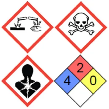 | 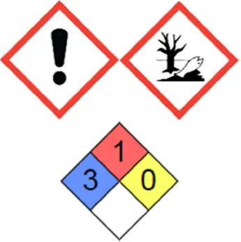 | 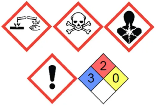 | Not reported for profisetinidin, prorobinetinidin, prodelphinidin and procyanidin |
Hazard statements for phenol, resorcinol, formaldehyde, and tannin with data from the Kim et al. (2018) and the National Institute for Occupational Safety Health (2018).
PEL, permissible exposure limit; REL, recommended exposure limit; TWA, time-weighted average over 8 h; STEL, short-term exposure limits over 15 min; GHS, globally harmonized system; NFPA, National fire protection association.
According to SilvaChimica (St Michelle Mondovi, Italy), provider of mimosa, quebracho, and tara tannins.
Synthesis of Porous Carbons
Condensed tannins have been used to produce a wide variety of high added-value materials. The tannin-derived products can be converted into carbon by high-temperature treatment. The resulting materials are glass-like due to the non-graphitizing nature of the precursor, and present isotropic properties and good electrical conductivity. As for petrochemical precursors, the synthesis of porous materials from tannin usually requires the preparation of a resin by crosslinking with formaldehyde, hexamine, or glutaraldehyde, among other possible aldehydes. Thus, different materials have been synthesized such as foams (Tondi et al., 2009; Lacoste et al., 2013; Jana et al., 2014; Szczurek et al., 2014; Delgado-Sánchez et al., 2018), gels (Szczurek et al., 2011a,b; Amaral-Labat et al., 2013; Braghiroli et al., 2019), microspheres (Grishechko et al., 2016), or polyHIPEs (Szczurek et al., 2013). Furthermore, tannin autocondensation reactions enable its polymerization without having to use crosslinkers, opening the way for the production of OMCs by self-assembly techniques (Schlienger et al., 2012; Braghiroli et al., 2016). The following section describes some of the methods used to obtain micro-mesoporous carbon materials from tannin, as well as their performance when used as electrodes for SCs, they are summarized in Table 3.
Table 3
| Tannin precursor/ Synthesis method | Carbon material | Activation/ Doping | BET area (m2 g−1) | Cell type | Electrolyte | Potential window (V) | Ce (F g−1) | References |
|---|---|---|---|---|---|---|---|---|
| Mimosa/Sol-gel | Cryo-CGs | –/– | 399–1 420 | T | 4 M H2SO4 | 1.0 | 30–109, at 2 mV s−1 | Amaral-Labat et al., 2012 |
| Mimosa/HTC | CMSs and CG-like | –/N, O | 442–684 | T | 4 M H2SO4 | 1.0 | 181–322, at 2 mV s−1 | Braghiroli et al., 2015b |
| Mimosa/HTC | Aero-, cryo- and xero-CGs | –/N, O | 496–864 | T | 4 M H2SO4 | 1.0 | 231–388, at 2 mV s−1 | Braghiroli et al., 2015c |
| Pine/HTC | CMSs and CG-like | –/N, O | 80–652 | 3-e 2-e | 1 M H2SO4 | 0.9 | 114–321, at 0.5 mV s−1 112–258, at 0.1 A g−1 | Sanchez-Sanchez et al., 2017b |
| Quebracho/ Microwave-assisted | MCs | –/P, N | 113–855 | 3-e | 1 M H2SO4 6 M KOH | 0.8 | 172–272, at 5 mVs−1 176–236, at 5 mVs−1 | Nasini et al., 2014 |
| Mimosa/Hard-templating | OMCs | –/– | 1006 | 3-e 2-e | 1 M H2SO4 | 0.8 | ~250, at 0.5 mVs−1 ~196, at 0.1 A g−1 | Sanchez-Sanchez et al., 2017a |
| Mimosa/ Phase separation | OMCs | CO2/– | 563–1137 | 3-e 2-e | 2 M H2SO4 | 0.8 | 158–286, at 0.5 mV s−1 Up to 244, at 0.1 A g−1 | Sanchez-Sanchez et al., 2018 |
| Mimosa/ Mechanosynthesis | OMCs | CO2/– | 567–2061 | 2-e | 1 M H2SO4 1 M Na2SO4 1 M TEABF4/ACN | 1.0 1.6 2.7 | 138–147, at 0.2 A g−1 94–100, at 0.2 A g−1 103–109, at 0.2 A g−1 | Castro-Gutiérrez et al., 2019 |
Summary of methods, properties and electrochemical performance of tannin-derived carbon materials.
Ce, specific electrode capacitance; HTC, hydrothermal carbonization; CGs, carbon gels; CMSs, carbon microspheres; MCs, mesoporous carbons; OMCs, ordered mesoporous carbons; T, T-type cell; 3-e, three-electrode cell; 2-e, two-electrode cell.
Sol-Gel
CGs were produced from mimosa tannin and formaldehyde (TF) organic cryogels (Amaral-Labat et al., 2012). The pH of mimosa tannin solutions was adjusted with either acetic acid or NaOH diluted in water to obtain a pH ranging from 3.3 to 7.3. Such solutions were placed in an oven at 85°C for 5 days, in which gelation and aging took place. After exchanging water for tert-butanol, the gels were freeze-dried to obtain TF cryogels. Finally, CGs were produced by carbonization of TF cryogels at 900°C. Surface areas from 399 to 1,420 m2 g−1 were obtained, with minimum values found for pH 4.3 and 5.3 and attributed to pore collapse during carbonization. The highest surface areas were found for pH > 6. This unusual development of surface area was ascribed to the presence of NaOH, which could act as an activating agent during the carbonization process. The textural characterization revealed that the CGs were mainly micro- and macroporous materials, with an unusually low amount of mesopores.
In order to test their electrochemical performance, the CGs were ground to prepare pellets by mixing the corresponding sample, carbon black and PVDF (75:5:20 wt. %), and then symmetrical SCs were assembled and tested in a T-type cell. CV tests were carried out from 2 to 50 mV s−1 using 4 M H2SO4 as electrolyte in a potential window of 1 V. The values of Ce of the CGs at 2 mV s−1 ranged from 30 to 109 F g−1, similar to the values found for more expensive carbon aerogels. As expected, the best performance was observed for the materials with the highest surface area. However, as the scan rate increased, the CV curves became narrower and lost their quasi-rectangular shapes, indicating a loss of SC behavior and resulting in a decrease of Ce. It was concluded that, although these CGs were highly porous, the values of capacitance were generally lower than expected due to the large amount of macropores that do not account for the capacitance. Besides, the sharp drop in Ce with the increase in scan rate was related to the absence of mesopores to facilitate the diffusion of electrolyte ions in the micropores.
Hydrothermal Carbonization
Hydrothermal treatments of aqueous solutions of tannins take advantage of their autocondensation at very acidic or basic pH. By varying pH, tannin concentration and temperature, it is possible to obtain gels or spheres. Besides, it is possible to perform N-doping in situ by using ammonia solutions instead of water during the HTC process. Several examples of the electrochemical performances of carbonized, tannin-derived, HTC materials are described below.
N-doped materials were produced by HTC of mimosa tannin (Braghiroli et al., 2015a,b). Two functionalization routes were followed: (i) dissolution of tannin in an aqueous ammonia solution, evaporation at room temperature, then dissolution of the solid residue in water solution followed by HTC; and (ii) dissolution of tannin in an aqueous ammonia solution followed by HTC. The former resultant material was called EAT (for “evaporated aminated tannin”), and the latter was called AT (for “aminated tannin”). A reference material, prepared by direct HTC of tannin in water, called T, was also synthesized. HTC was carried out at temperatures ranging from 180 to 220°C for 24 h, and the recovered materials were carbonized at 900°C. The morphology radically changed from CNSs for the reference materials to CG structure for the EAT-materials, while the carbon obtained by the AT-route presented a mixed morphology, see Figures 10A–C. The carbon materials exhibited surface areas between 113 and 684 m2 g−1. AT- and T-materials had a high proportion of ultramicropores (pores of width <0.7 nm), higher than 79%, while EAT-materials presented a majority of mesopores. The micropore volume remained around ~0.21 cm3 g−1 in almost all cases. Regarding the presence of heteroatoms, the AT-route introduced the highest amount of nitrogen into the material with a maximum of 8.1 wt. % for HTC carried out at 220°C. The oxygen content decreased with the temperature, regardless of the functionalization route, remaining between 5.6 and 15.9 wt. %.
Figure 10
The electrochemical performances of carbon materials derived from HTC at 180 and 210°C were evaluated (Braghiroli et al., 2015b). Electrodes for symmetrical SCs were prepared by mixing the powdered carbon material with carbon black and PVDF (75:5:20 wt. %), and assembled in a T-type cell, using 4 M H2SO4 as electrolyte. CV tests were carried out using a potential window of 1 V. The obtained curves were asymmetric, indicating the existence of considerable resistance; examples are shown in Figure 10D. CV curves also showed humps characteristic of redox reactions occurring due to the high content of heteroatoms (N and O). Thanks to the pseudocapacitance contributions of these reactions, Ce reached values as high as 322 F g−1 at 2 mV s−1. However, as the scan rate increased, Ce dropped considerably. This behavior was attributed to the large size of the mesopores, 27–34 nm, which do not significantly account for the capacitance and do not successfully shorten the ion diffusion pathways as the narrower mesopores would. In order to study the effect of doping, the interfacial capacitance was calculated by normalizing Ce by the surface area and was plotted against the O and N contents (wt. %), see Figures 10E,F. It was found that the interfacial capacitance increased with the O content, but showed a maximum value for an N content between 3 and 6 wt. %. A large amount of heteroatoms is believed to block the pores, resulting in reduced electrochemical performance.
A follow-up study evaluated the electrochemical performances of N-doped CGs produced by HTC of EAT (Braghiroli et al., 2015c). In this case, aqueous solutions of different concentrations of EAT were submitted to HTC at 180°C for 24 h. The recovered products were then dried to produce organic aerogels, cryogels, or xerogels, and the latter materials were further carbonized at 900°C to obtain N-doped CGs. The materials exhibited both micro- and mesoporosity in a proportion of ~40/60, and the highest surface areas were obtained for the highest concentration of EAT, reaching a maximum of 864 m2 g−1. For all the CGs, the N content remained around 2.5 wt. %, and an O content higher than 13.9 wt. % was observed. Electrodes for symmetrical SCs were prepared and assembled as described above for AT- and EAT-materials. Again, the CV curves were asymmetrical with the characteristic humps due to redox reactions, similar to those displayed in Figure 10D. At a scan rate of 2 mV s−1, the ultramicropore volume was found to have more impact on the Ce values than the surface area. The capacitance increased significantly up to an ultramicropore volume of 0.2 cm3 g−1, for which it reached a maximum value of ~400 F g−1. A further increase in the volume did not affect the capacitance values. Contrary to what was expected, the values were more scattered than in the trends previously observed when comparing the effect of O and N doping on the interfacial capacitance with the results of Braghiroli et al. (2015b) (see again Figures 10E,F). Recalling that all CGs have a similar N content, this scattering might be due to their larger differences of pore texture. The enhancement in the capacitance due to N-doping could be positively or negatively influenced by, for example, a larger or lower surface area, explaining the scattering of the values in Figure 10E. An analogous reasoning would also explain the behavior observed for the effect of the O content in Figure 10F.
Another study proved that N-doped carbon materials can also be obtained by HTC treatment of aminated pine tannin (Sanchez-Sanchez et al., 2017b). The synthesis reported by Braghiroli et al. (2015b) was used by replacing mimosa tannin with pine tannin and carrying out the HTC process at 190°C. The tannin extraction from Pinus pinaster was carried out by two methods. In method (i), a mix of pine bark and water in weight ratio of 1:6 was heated up to 90°C for 90 min. In method (ii), the same mix used in (i) but in a 1:5 weight ratio was heated up to 75°C; then, an aqueous solution containing 2 and 0.5% of Na2SO3 and Na2CO3, respectively, was added to the mixture while maintaining the temperature for an additional 60 min. The suspensions from methods (i) and (ii) were filtered, washed with water and spray-dried, leading to tannin powders referred as TW or TNa, respectively. The morphology of the carbon materials was similar to that obtained from the same treatment of mimosa tannin, i.e., showing a transition from spherical particles to a gel-like structure. Most of the materials presented a high microporosity that led to surface areas between ~300 and ~700 m2 g−1. However, samples obtained from the direct HTC of TNa and from the EAT-route did not develop any porous texture, which is the reason why they were excluded from the electrochemical tests.
A three-electrode configuration was used to evaluate the electrochemical performance of the pine tannin-derived materials in a potential window of 0.9 V in 1 M H2SO4. Electrodes were prepared by mixing the porous carbon, carbon black and PTFE (85:5:10 wt. %). Faradaic peaks were observed on the CV curves at low scan rates (0.5 mV s−1). Remarkably, the TW-materials retained a quasi-rectangular CV curve for a high scan rate of 1 V s−1, but the deviations from the ideal rectangular shape suggest that the diffusion of ions in the narrow micropores was hindered. At low scan rate, Ce of TW-materials was above 200 F g−1 due pseudocapacitance contributions. However, for a scan rate of 20 mV s−1, Ce has already decreased to ~40% of its original values because redox reactions do not occur at faster scan rates. Capacitance then continued to decrease but at a considerably slower rate, almost reaching a plateau at 1 V s−1. In addition, a linear increase in interfacial capacitance with the surface concentration of heteroatoms (N and O) was observed for the TW-materials. As the scan rate increased, the slope of the fitted line decreased, becoming almost a horizontal line at 1 V s−1. This implies that, for fast scan rates, the heteroatom content does not contribute to the capacitance, in agreement with the previous statements. TNa-A sample, obtained from aminated TNa, exhibited the lowest performance, whatever the scan rate and despite a surface area and density of surface functionalities similar to those of other materials from the TW-series. Furthermore, TNa-A exhibited the lowest value of interfacial capacitance, indicating that a large part of the surface of the material was not accessible to the electrolyte ions. The high amount of surface functionalities was not able to compensate the lack of charge storage sites resulting in the poor performance observed. In addition, GCD and EIS measurements were carried out using a two-electrode cell. The calculation of Ce from the GCD curves gave values similar to those obtained from the CV curves, and a drastic drop in capacitance was observed as the applied current increased. Again, TNa-A had the lowest performance. In general, the doped materials from the TW-series had the highest values of capacitance, confirming the beneficial role of surface modification. However, there are still some drawbacks to the doping procedure followed, as the EIS and GCD tests also revealed that the doped materials had larger EDR values and lower stability after continuous cycling than their non-doped counterparts.
Microwave-Assisted Synthesis
P- and N-doped carbons (PNDCs) have been successfully produced by a microwave technique using quebracho tannin as carbon precursor (Gopal Bairi et al., 2013). Melamine and hexamine were used as N source and polyphosphoric acid as P source. The synthesis was carried out by dissolving melamine and tannin in water, then a solution of hexamine was added and the whole mixture was heated to its boiling point. Finally, the resultant material was mixed with polyphosphoric acid and subjected to microwaves for 30 min. The temperature reached was estimated to be between 1,200 and 1,400°C during the process carried out in a 1.25 kW−2.4 GHz microwave oven. The physicochemical properties and performances of the PNDCs obtained from three different tannin:melamine:hexamine molar ratios as electrodes for SCs were further studied by the same research group (Nasini et al., 2014). The samples were referred to as PNDC-x, where x = 1, 2, or 3: the higher the value of x, the lower the amount of melamine and hexamine used for synthesis.
A large amount of heteroatoms was successfully introduced on the surface of the carbon. However, this was achieved by sacrificing considerably the available surface. The sample PNDC-1, having the highest content of surface functionalities (N 9.7 at. %, P 9.0 at. %, and O 14.9 at. %), thus had the lowest BET area, 113 m2 g−1 due to an accumulation of heteroatoms that could hinder access to the pores. Moreover, the higher contents of N and P are the consequence of the use of large quantities of hexamine and polyphosphoric acid, both substances reducing the amount of gases released during pyrolysis, increasing the carbon yield, but also reducing the development of the porous texture. Decreasing the level of doping increased the surface area and increased the volumes of micro- and mesopores. The sample PNDC-3 thus had the lowest content of heteroatoms and exhibited a surface area of 855 m2 g−1 with a total pore volume of 0.65 cm3 g−1. Intermediate values of heteroatom content and textural properties were found for PNDC-2. PNDCs are mesoporous materials, and most of their pore volume is due to narrow mesopores (of width ~3–4 nm) at the levels of 99, 78, and 89% for PNDC-1, PNDC-2, and PNDC-3, respectively.
The electrochemical performance of electrodes composed of PNDC, carbon black and PTFE (90:5:5 wt. %) was evaluated in a three-electrode cell using either 1 M H2SO4 or 6 M KOH as electrolytes. The CV curves of all materials in acidic medium revealed the typical peaks associated with redox reactions. At 5 mV s−1, the calculated Ce for PNDC-2 and PNDC-3 was 272 and 246 F g−1 and, despite its low surface area, PNDC-1 exhibited a capacitance of 172 F g−1 mainly due to pseudocapacitance contributions. As expected, Ce decreased for higher scan rates. A faster drop in capacitance was observed for PNDC-2 than for PNDC-3. At 100 mV s−1, PNDC-2 lost 30% of its capacitance, while PNDC-3 lost only 12%. The higher content of heteroatoms of PNDC-2, compared to PNDC-3, implies that at low scan rate, the contributions of pseudocapacitance are larger. However, at faster rates, redox reactions no longer occur, which reduces the performance of the material. On the other hand, the more stable performance of PNDC-3 is explained by the strong presence of mesopores and a low content of heteroatoms. Thus, for this material, the charge is mainly stored by an EDL mechanism that is not affected by an increase in the scan rate because the mesopores facilitate the diffusion of ions. In alkaline medium, PNDC-3 exhibited a behavior similar to that in acidic medium. However, lower values of Ce were reached; this decrease in capacitance might be caused by the larger size and lower mobility of ions in KOH, compared to those in H2SO4 (see Table 1). PNDC-2 exhibited the best performance of the series across the range of scan rates, attributed to a combination of sufficiently high surface area, pore volume and pseudocapacitance contribution of the surface functionalities that are reactive in alkaline media. Subsequent studies have extended this synthesis method to produce PNDCs from aminated quebracho tannin (Bairi et al., 2015) and Si- and P-doped carbons from quebracho tannin (Ramasahayam et al., 2015). In both studies, behaviors and values of capacitance similar to those detailed above were found.
Hard-Templating
OMCs have been produced by hard-templating using mimosa tannin and other tannin-related molecules such as phloroglucinol, gallic acid, and catechin (Sanchez-Sanchez et al., 2017a). SBA-15 silica template was synthesized using a mixture of tetraethyl orthosilicate (TEOS), Pluronic® P123, HCl, and water (molar ratio 1:0.017:6.04:145.8) that was stirred at 40°C for 4 h and aged at 125°C for 72 h. The product, recovered by filtration, was heat-treated in air at 550°C for 6 h. An ethanol solution of the corresponding precursor (0.01 mol/40 mL) was added to the SBA-15, previously degassed under vacuum (150°C, 2 h). Ethanol was evaporated under vacuum and, if necessary, the obtained solid was washed with deionized water to eliminate the excess of precursor deposited on the silica particles. These composites were carbonized under nitrogen flow according to a two-step temperature program: heating from room temperature to 100°C (1°C min−1) and holding the temperature for 2 h in order to remove moisture and polymerize the precursors, then heating up to 900°C (2°C min−1) and holding the temperature for 1 h. The template was removed from the carbonized composites with HF, washed with deionized water and finally dried at 80°C for 12 h. The OMCs were labeled according to their precursors as TanC, PhC, GaC, and CatC for tannin, phloroglucinol, gallic acid, and catechin, respectively.
Figure 11A shows the schematic synthesis process and TEM images of the produced OMCs. TEM images revealed some discontinuities in the structure for CatC and TanC, indicating that catechin and mimosa tannin permeated the template heterogeneously. The large size of these molecules could block some of the pores, preventing the complete filling of the template and resulting in the gaps observed. XRD measurements revealed that all materials exhibited a structure in the p6mm space group (2D hexagonal), and that the long-range order decreased as the size of the precursor molecule increased, in agreement with TEM results. Nevertheless, TanC had the advantage of achieving the highest carbon yield (80%) among the carbon precursors used for this study. The textural characterization showed that all the OMCs exhibited BET surface areas of ~1,000 m2 g−1 and total pore volumes higher than 0.87 cm3 g−1, of which 75–87% came from mesopores. Chemical characterization by elemental analysis and XPS revealed oxygen as the main heteroatom in the material, which was expected given its abundance in the precursor molecules.
Figure 11
The electrochemical performance was evaluated in 1 M H2SO4. CV tests were carried out in a three-electrode cell while GCD and EIS measurements were done in a two-electrode cell. The electrodes, prepared by mixing the OMC, carbon black and PTFE (85:5:10 wt. %), were spread onto graphite foil and pressed at 5 MPa. Rectangular CV curves were observed up to a scan rate of 100 mV s−1. At 0.5 mV s−1, Ce reached values higher than 200 F g−1, which are in the same range of other carbons with similar textural properties but that required additional oxidation post-treatments (Jurewicz et al., 2004; Tanaka et al., 2015). GCD tests led to quasi-triangular curves whose slight curvature suggests the occurrence of redox reactions due to the presence of oxygen on the surface. For both CV and GCD tests, as the charging rate increased (scan rate or applied current), Ce decreased. In particular, TanC presented a capacitance retention of 42 % at 100 mV s−1 and 51 % at 12 A g−1, higher than the ~30% retention reported for the pine tannin-derived HTC carbons described above and tested under similar conditions (Sanchez-Sanchez et al., 2017b). The enhanced performance of OMCs as electrodes for SCs confirms the beneficial role of a hierarchical porous structure as a means of improving ion diffusion in the carbon material.
Soft-Templating
Phase Separation
Mimosa tannin was successfully used as precursor to produce OMCs by an easy and simple phase-separation method (Braghiroli et al., 2016). The synthesis only required the mixing, at room temperature, of two solutions: one of mimosa tannin, the other of Pluronic® F127. Immediately after mixing, a phase-separation occurred and after 2 days, complete sedimentation of the resultant mesophase was observed. The recovered mesophase was dried at 80°C and carbonized at temperatures ranging from 400 to 900°C. The pH of the tannin solution was varied from 0 to 4.2 but no significant change in the carbon yield or the porosity were observed by modifying this parameter. The synthesis process is shown in Figure 11B, and TEM images of OMCs obtained for different pH values are presented. Thermogravimetric analysis showed that the Pluronic® F127 degrades at 400°C, so carbonization at higher temperatures is required to remove it completely from the material. Higher temperature treatments resulted in more developed microporosity and consequently higher surface areas: a maximum of ~700 m2 g−1 BET area was reached. These values of surface area are ~200 m2 g−1 higher than those obtained from an EISA method also using mimosa tannin as precursor and carbonizing the mesophase at a maximum temperature of 850°C (Schlienger et al., 2012).
Some modifications to the phase-separation method were made in a following study that also investigated the effect of the assembly temperature (Sanchez-Sanchez et al., 2018). The pH was varied from 1 to 4.5 and the assembly temperature ranged from 10 to 30°C. The mixed tannin/F127 solutions were keep at a constant assembly temperature for 72 h, and then they remained at room temperature for 5 days until complete phase-separation. The retrieved resins were dried at 60°C and carbonized in two consecutive steps: increasing the temperature up to 400°C, holding it for 4 h, and then heating until 900°C and holding for 1 h. In agreement with the previous work of Braghiroli et al. (2016), it was found that for a fixed temperature, the pH did not change considerably the porous texture. On the contrary, for a given pH, an effect of the assembly temperature was observed, where the greatest change occurred at pH 3 after increasing the temperature from 20 to 30°C. The solution of pH 3 assembled at 30°C gave the carbon material, called F3/30, having the highest values of surface area and micro- and mesopore volumes, 750 m2 g−1, 0.24 and 0.49 cm3 g−1, respectively. Therefore, F3/30 was selected for CO2 activation to improve its porous texture further.
As expected, for the resultant activated carbon, labeled C3/30, an increased surface area (~1,100 m2 g−1) and a widening of pores were observed. Three- and two-electrode cells were used for its electrochemical characterization, using 2 M H2SO4 as electrolyte and electrodes composed of a mixture of the studied carbon, carbon black and PTFE (85:5:10 wt. %). It was found that the main mechanism of storage of energy was the EDL, since the contribution of pseudocapacitance from heteroatoms was negligible. In addition, CV and GCD tests showed that the activation process increased the capacitance of the material by 1.5 times, probably due to the widening and opening of previously blocked pores, which resulted in improved connectivity of the pore network and surface accessibility to electrolyte ions. Even more, the electrochemical tests showed that the rate capabilities of C3/30 were comparable to those measured for the hard-templated TanC obtained from the same precursor, mimosa tannin, but through a less eco-friendly synthesis method (Sanchez-Sanchez et al., 2017a), thus showing the advantage of the soft-template method.
Mechanosynthesis
Mechanosynthesis methods, for which mechanical energy is supplied to the materials by shearing, stretching, or grinding (James et al., 2012), are commonly used to produce ceramics, metal alloys, and organic materials (Kaupp, 2009, 2011; Wang, 2013). This type of solid-state synthesis has attracted interest for producing OMCs since they require little or no solvent, short synthesis times compared to other methods and fewer synthesis steps, which results in cheaper and more eco-friendly products (James et al., 2012; Wang, 2013; Zhu et al., 2016). Ball-milling has been found to be an appropriate method for synthesizing OMCs, as it can provide higher energy and repeatability than manual grinding, thereby increasing its potential for use on an industrial scale (Wang, 2013). OMCs were indeed obtained by ball-milling mimosa tannin, Pluronic® F127 and metal acetates used as crosslinkers. After washing, drying and carbonization, 2D hexagonal geometries were observed (Zhang et al., 2017).
More recently, another study reported an easy, one-pot mechanosynthesis method for preparing OMCs with a 2D hexagonal structure by ball-milling, where only mimosa tannin (T), Pluronic® F127 (P) and small amounts of water (W) were needed (Castro-Gutiérrez et al., 2018). This surfactant-water-assisted mechanochemical mesostructuration (SWAMM) method does not involve curing or drying steps before carbonization or the use of hazardous substances as crosslinkers. The influence of synthesis parameters such as milling time, pH, P:W weight ratio and carbonization temperature on the textural properties of the obtained carbon materials was analyzed. Optimal values of milling time (60 min) and pH (unchanged) to produce uniform PSDs were found and it was shown that by changing the P:W weight ratio, it was possible to produce either ordered or disordered mesoporous materials. Increasing the carbonization temperature from 900 to 1,100°C resulted in the development of micro- and mesoporosity, but higher temperatures, up to 1,500°C, did not seem to have a significant impact on the textural properties of the OMCs. Nonetheless, Raman spectra revealed that despite being in the non-graphitizable regime, higher carbonization temperatures yielded materials with improved long-range order at the nanoscale. Several applications were explored with promising results, such as the adsorption of hydrocarbons from water, the adsorption of CO2 and, after activation, the storage of energy in SCs.
Energy storage in SCs was further investigated in a follow-up study, where the electrochemical performances of activated OMCs (AOMCs) produced by the SWAMM method were evaluated (Castro-Gutiérrez et al., 2019). The OMC was placed inside a tubular furnace and heated up to 900°C (5°C min−1) under N2 flow, then N2 was switched to CO2 to physically activate the samples for durations ranging from 15 to 120 min. The samples were labeled At-CTPW with t standing for the time in minutes. TEM images of as-synthesized and A90-CTPW materials are shown in Figure 11C with a scheme of the synthesis method. It was observed that the ordered mesoporous structure was maintained up to a burn-off of 78% (A90-CTPW). The surface area of the AOMCs increased with burn-off, reaching a maximum of ~2,000 m2 g−1 for a burn-off of ~80%. Higher activation times resulted in a sudden decrease of surface area due to pore widening and merging, evidenced by the PSDs and the derived calculations of ultramicro-, supermicro- (0.7 < pore width < 2 nm) and mesopore volumes. Electrodes were prepared with samples A30- to A-90-CTPW that were mixed with carbon black and PTFE (85:5:10 wt. %) to form a paste from which electrodes with carbon loads of ~10 mg cm−2 were cut and assembled in a two-electrode cell.
CV tests performed in 1 M H2SO4 revealed rectangular curves at 5 mV s−1, with Ce values between 136 and 160 F g−1, the maximum being reached by A75-CTPW. Only A60- and A75-CTPW retained more than 60% of their initial capacitance at 500 mV s−1, which was attributed to a combination of high surface area originating from a high micropore volume (<0.50 cm3 g−1), providing multiple charge storage sites, and a suitable PSD, favoring ion diffusion at high charging rates. A further characterization was then carried out on these samples, using also 1 M TEABF4/ACN as electrolyte. Examples of CV curves in aqueous and organic electrolytes are shown in Figures 12A,D. During GCD tests, A60- and A75-CTPW exhibited triangular curves in the aqueous electrolyte. However, A75-CTPW performed better once the applied current increased, showing a capacitance retention, Cret, of 70%, whereas that observed for A60-CTPW was only 51%, both at a high current of 80 A g−1, see Figure 12B. In the organic electrolyte, A60- and A75-CTPW behaved in a similar way and a more rapid drop of Cret was observed compared to that in the aqueous electrolyte (Figure 12E). This was ascribed to the larger size and lower mobility of the ions in the organic electrolyte that increased the resistance of the SC cell, thereby decreasing its performance. In all cases, the tannin-derived AOMCs presented superior or comparable rate capabilities than those previously reported for similar materials (also displayed in Figures 12B,E) with the advantage of being produced by an easy and eco-friendly method. Even more, A60- and A75-CTPW exhibited great long-term stability over time and after continuous cycling at 5 A g−1. More precisely, in the aqueous electrolyte, Cret remained at ~98% after 10,000 cycles and ~94% after 50 h of potentiostatic hold at 1 V, while in the organic electrolyte Cret was above 90% after 8,000 cycles and reached 86 % after 72 h of potentiostatic hold at 2.7 V.
Figure 12
As expected, the values of E and P in organic electrolyte are considerably higher than in aqueous electrolyte, see Figures 12C,F. Indeed, a maximum E of 28 Wh kg−1 (at a P output of 138 W kg−1) was attained in the organic electrolyte, more than 5 times the maximum E of 5 Wh kg−1 (at a P output of 44 W kg−1) reached in the aqueous electrolyte. For the organic electrolyte, it is important to note that, despite the drastic drop in E observed, the selected AOMCs were still able to store ~13 Wh kg−1 at a high P of 12 kW kg−1. Finally, the electrochemical performances of the selected AOMCs were also evaluated in 1 M Na2SO4, a neutral aqueous electrolyte. The results are shown in Figures 12G–I. In general, lower values of Ce and Cret were found compared to those obtained in acidic medium (H2SO4). The lower performance of the SCs in Na2SO4 can be related to a larger size and lower mobility of the Na+ ion. The larger size results in fewer charge storage sites, leading to a lower capacitance while the lower mobility hinders diffusion at high charging rates. Nevertheless, the advantage of the neutral electrolyte lies in the possibility of extending the operating potential window. Consequently, an increase of ~60% of the maximum E was observed with respect to that reached in acidic medium.
Summary and Perspectives
SCs are devices with high power outputs, rate capability, cyclability, and long lifetimes. However, the amount of stored energy in SCs is lower than that found in batteries. In this sense, research in recent decades has focused on the development of new materials that can improve SC performance, not only by increasing the storage capacity but also by increasing the rate capability and the long-term stability. Porous carbons have proven to be adequate materials for SC electrodes and, indeed, ACs are already widely used in commercial devices. Multiple synthesis methods have been developed to control the textural and chemical properties of porous carbons; in particular, templated carbons, such as OMCs, are promising electrode materials because they can be produced with different morphologies, high surface area and adjusted hierarchical porosity. The possibility of tuning the pore size is of significant importance as it allows full accessibility of the electrolyte into the material, while the hierarchical structure provides channels facilitating the diffusion of ions toward the smallest accessible pores. The modification of the surface chemistry of porous carbons presents another route to increase SC performance, and doping with oxygen, nitrogen or other heteroatoms can induce redox reactions that increase the energy stored in the device. Even if all the surface functionalities do not always induce redox reactions, doping can also improve other characteristics of the material such as electrical conductivity, wettability, or stability.
Besides, the quest for environmentally friendly technologies has pushed research to find substitutes for synthetic and hazardous molecules commonly used as carbon precursors or crosslinkers. Among the various biosourced precursors, tannins are excellent alternatives to petrochemical carbon sources because of their phenolic nature. In addition, condensed tannins have a reactivity similar to that of phenol or resorcinol, so tannins can replace them in already established synthesis methods. The autocondensation property of condensed tannins also offers the opportunity of avoiding the use of crosslinkers, which makes them suitable precursors for self-assembly methods. As described in the last section of this review, several studies have demonstrated the versatility of tannins to produce porous carbon materials through “green” processes reducing or even eliminating the use of toxic or hazardous substances and thus decreasing their negative environmental impact. In addition, tannins are extracted industrially and marketed on a large scale, because they are essential for the leather, wine and food industry. Therefore, they are readily available at low cost. Thus, the production of porous carbons from tannin will provide and add value to this precursor derived from biomass.
In general, the main disadvantages of producing advanced porous carbon materials are their complex multi-step procedures and their tedious synthesis. Therefore, future materials research efforts for SCs should continue to focus on the development and optimization of easy and environmentally friendly procedures such as one-pot synthesis methods that allow for in situ doping and/or activation of biomass or biosourced precursors. Simplifying and reducing the number of steps would reduce costs and increase scalability, resulting in a use of biosourced carbons that is more widespread in commercial SC devices.
Statements
Author contributions
JC-G performed writing original draft and conceptualization. AC performed writing—review and editing. VF performed conceptualization, supervision, funding acquisition, and writing—review and editing. All authors contributed to the article and approved the submitted version.
Funding
This study was partly funded by the French PIA project Lorraine Université d'Excellence, reference ANR-15-IDEX-04-LUE and the TALiSMAN project, funded by FEDER (2019-000214).
Acknowledgments
JC-G gratefully acknowledges CONACYT-SENER (601021/438978) for the scholarship awarded to support her Ph.D. studies, resulting in the work presented herein.
Conflict of interest
The authors declare that the research was conducted in the absence of any commercial or financial relationships that could be construed as a potential conflict of interest.
References
1
AcostaR.NabarlatzD.Sánchez-SánchezA.JagielloJ.GadonneixP.CelzardA.et al. (2018). Adsorption of bisphenol A on KOH-activated tyre pyrolysis char. J. Environ. Chem. Eng.6, 823–833. 10.1016/j.jece.2018.01.002
2
Amaral-LabatG.GrishechkoL. I.FierroV.KuznetsovB. N.PizziA.CelzardA. (2013). Tannin-based xerogels with distinctive porous structures. Biomass Bioenergy56, 437–445. 10.1016/j.biombioe.2013.06.001
3
Amaral-LabatG.SzczurekA.FierroV.SteinN.BoulangerC.PizziA.et al. (2012). Pore structure and electrochemical performances of tannin-based carbon cryogels. Biomass Bioenergy39, 274–282. 10.1016/j.biombioe.2012.01.019
4
AnekeM.WangM. (2016). Energy storage technologies and real life applications – a state of the art review. Appl. Energy179, 350–377. 10.1016/j.apenergy.2016.06.097
5
AyalaP.ArenalR.RümmeliM.RubioA.PichlerT. (2010). The doping of carbon nanotubes with nitrogen and their potential applications. Carbon48, 575–586. 10.1016/j.carbon.2009.10.009
6
BairiV. G.NasiniU. B.Kumar RamasahayamS.BourdoS. E.ViswanathanT. (2015). Electrocatalytic and supercapacitor performance of phosphorous and nitrogen co-doped porous carbons synthesized from aminated tannins. Electrochim. Acta182, 987–994. 10.1016/j.electacta.2015.10.011
7
BardA. J.FaulknerL. R. (2001). Electrochemical Methods: Fundamentals and Applications, 2 Edn. Hoboken, NJ: Wiley.
8
BastaA. H.FierroV.El-SaiedH.CelzardA. (2009). 2-Steps KOH activation of rice straw: an efficient method for preparing high-performance activated carbons. Bioresour. Technol.100, 3941–3947. 10.1016/j.biortech.2009.02.028
9
BeguinF.FrackowiakE (Eds.). (2013). Supercapacitors: Materials, Systems, and Applications. Weinheim: John Wiley & Sons, Ltd.
10
BerenguerR.NishiharaH.ItoiH.IshiiT.MorallónE.Cazorla-AmorósD.et al. (2013). Electrochemical generation of oxygen-containing groups in an ordered microporous zeolite-templated carbon. Carbon54, 94–104. 10.1016/j.carbon.2012.11.007
11
BraghiroliF. L.Amaral-LabatG.BossA.LacosteC.PizziA. (2019). Tannin gels and their carbon derivatives: a review. Biomolecules9:587. 10.3390/biom9100587
12
BraghiroliF. L.FierroV.IzquierdoM. T.ParmentierJ.PizziA.CelzardA. (2012). Nitrogen-doped carbon materials produced from hydrothermally treated tannin. Carbon50, 5411–5420. 10.1016/j.carbon.2012.07.027
13
BraghiroliF. L.FierroV.IzquierdoM. T.ParmentierJ.PizziA.DelmotteL.et al. (2015a). High surface – highly N-doped carbons from hydrothermally treated tannin. Ind. Crops Prod.66, 282–290. 10.1016/j.indcrop.2014.11.022
14
BraghiroliF. L.FierroV.ParmentierJ.PascA.CelzardA. (2016). Easy and eco-friendly synthesis of ordered mesoporous carbons by self-assembly of tannin with a block copolymer. Green Chem. 18, 3265–3271. 10.1039/C5GC02788H
15
BraghiroliF. L.FierroV.SzczurekA.SteinN.ParmentierJ.CelzardA. (2015b). Electrochemical performances of hydrothermal tannin-based carbons doped with nitrogen. Ind. Crops Prod.70, 332–340. 10.1016/j.indcrop.2015.03.046
16
BraghiroliF. L.FierroV.SzczurekA.SteinN.ParmentierJ.CelzardA. (2015c). Hydrothermally treated aminated tannin as precursor of N-doped carbon gels for supercapacitors. Carbon90, 63–74. 10.1016/j.carbon.2015.03.038
17
CAPPEQ (2019a). How to Extract Tannin? Tannins. Available online at: https://www.tannins.org/how-to-extract-tannin/ (accessed February 3, 2020).
18
CAPPEQ (2019b). Tannin, A History Close to Your Own. Tannins. Available online at: https://www.tannins.org/history-of-tannin/ (accessed February 3, 2020).
19
CAPPEQ (2019c). Tannin: One Substance, Different Applications. Tannins. Available online at: https://www.tannins.org/applications/ (accessed February 3, 2020).
20
Castro-GutiérrezJ.DíezN.SevillaM.IzquierdoM. T.GhanbajaJ.CelzardA.et al. (2019). High-rate capability of supercapacitors based on tannin-derived ordered mesoporous carbons. ACS Sust. Chem. Eng. 7, 17627–17635. 10.1021/acssuschemeng.9b03407
21
Castro-GutiérrezJ.Sanchez-SanchezA.GhanbajaJ.DíezN.SevillaM.CelzardA.et al. (2018). Synthesis of perfectly ordered mesoporous carbons by water-assisted mechanochemical self-assembly of tannin. Green Chem.20, 5123–5132. 10.1039/C8GC02295J
22
ChaJ. S.ParkS. H.JungS.-C.RyuC.JeonJ.-K.ShinM.-C.et al. (2016). Production and utilization of biochar: a review. J. Industr. Eng. Chem.40, 1–15. 10.1016/j.jiec.2016.06.002
23
ChangP.-Y.BindumadhavanK.DoongR.-A. (2015). Size effect of ordered mesoporous carbon nanospheres for anodes in li-ion battery. Nanomaterials5, 2348–2358. 10.3390/nano5042348
24
ChenC.-M.ZhangQ.ZhaoX.-C.ZhangB.KongQ.-Q.YangM.-G.et al. (2012). Hierarchically aminated graphene honeycombs for electrochemical capacitive energy storage. J. Mater. Chem. 22:14076. 10.1039/c2jm31426f
25
ChenH.LiuD.ShenZ.BaoB.ZhaoS.WuL. (2015). Functional biomass carbons with hierarchical porous structure for supercapacitor electrode materials. Electrochim. Acta180, 241–251. 10.1016/j.electacta.2015.08.133
26
CiszewskiM.KoszorekA.RadkoT.SzatkowskiP.JanasD. (2019). Review of the selected carbon-based materials for symmetric supercapacitor application. J. Elec. Mater.48, 717–744. 10.1007/s11664-018-6811-7
27
ConteM. (2010). Supercapacitors technical requirements for new applications. Fuel Cells10, 806–818. 10.1002/fuce.201000087
28
de Hoyos-MartínezP. L.MerleJ.LabidiJ.Charrier – El BouhtouryF. (2019). Tannins extraction: a key point for their valorization and cleaner production. J. Clean. Prod.206, 1138–1155. 10.1016/j.jclepro.2018.09.243
29
Delgado-SánchezC.Santiago-MedinaF.FierroV.PizziA.CelzardA. (2018). Optimisation of “green” tannin-furanic foams for thermal insulation by experimental design. Mater. Des.139, 7–15. 10.1016/j.matdes.2017.10.064
30
DengY.XieY.ZouK.JiX. (2016). Review on recent advances in nitrogen-doped carbons: preparations and applications in supercapacitors. J. Mater. Chem. A4, 1144–1173. 10.1039/C5TA08620E
31
DíezN.FerreroG. A.SevillaM.FuertesA. B. (2019). A sustainable approach to hierarchically porous carbons from tannic acid and their utilization in supercapacitive energy storage systems. J. Mater. Chem. A7, 14280–14290. 10.1039/C9TA01712G
32
ElmouwahidiA.Castelo-QuibénJ.Vivo-VilchesJ. F.Pérez-CadenasA. F.Maldonado-HódarF. J.Carrasco-MarínF. (2018). Activated carbons from agricultural waste solvothermally doped with sulphur as electrodes for supercapacitors. Chem. Eng. J.334, 1835–1841. 10.1016/j.cej.2017.11.141
33
FeinleA.ElsaesserM. S.HüsingN. (2016). Sol–gel synthesis of monolithic materials with hierarchical porosity. Chem. Soc. Rev. 45, 3377–3399. 10.1039/C5CS00710K
34
FengS.LiW.WangJ.SongY.ElzatahryA. A.XiaY.et al. (2014). Hydrothermal synthesis of ordered mesoporous carbons from a biomass-derived precursor for electrochemical capacitors. Nanoscale6, 14657–14661. 10.1039/C4NR05629A
35
FerreroG. A.FuertesA. B.SevillaM. (2015). N-doped microporous carbon microspheres for high volumetric performance supercapacitors. Electrochim. Acta168, 320–329. 10.1016/j.electacta.2015.04.052
36
FierroV.MuñizG.BastaA. H.El-SaiedH.CelzardA. (2010). Rice straw as precursor of activated carbons: activation with ortho-phosphoric acid. J. Hazard. Mater.181, 27–34. 10.1016/j.jhazmat.2010.04.062
37
FierroV.Sánchez-SánchezA.CelzardA. (2018). Tannins as precursors of supercapacitor electrodes, in Sustainable Energy Technologies, eds Rincón-MejíaE.de las HerasA. (Boca Raton, FL: CRC Press), 201–228.
38
FierroV.Torné-FernándezV.CelzardA. (2007). Methodical study of the chemical activation of Kraft lignin with KOH and NaOH. Microp. Mesopor. Mater.101, 419–431. 10.1016/j.micromeso.2006.12.004
39
FierroV.Torné-FernándezV.MontanéD.CelzardA. (2005). Study of the decomposition of kraft lignin impregnated with orthophosphoric acid. Thermochim. Acta433, 142–148. 10.1016/j.tca.2005.02.026
40
FrackowiakE. (2007). Carbon materials for supercapacitor application. Phys. Chem. Chem. Phys.9:1774. 10.1039/b618139m
41
FrackowiakE.BeguinF. (2001). Carbon materials for the electrochemical storage of energy in capacitors. Carbon39, 937–950. 10.1016/S0008-6223(00)00183-4
42
FrackowiakE.LotaG.MachnikowskiJ.Vix-GuterlC.BéguinF. (2006). Optimisation of supercapacitors using carbons with controlled nanotexture and nitrogen content. Electrochim. Acta51, 2209–2214. 10.1016/j.electacta.2005.04.080
43
FuertesA. B.FerreroG. A.DiezN.SevillaM. (2018). A green route to high-surface area carbons by chemical activation of biomass-based products with sodium thiosulfate. ACS Sust. Chem. Eng. 6, 16323–16331. 10.1021/acssuschemeng.8b03264
44
GaoL.PengA.WangZ. Y.ZhangH.ShiZ.GuZ.et al. (2008). Growth of aligned carbon nanotube arrays on metallic substrate and its application to supercapacitors. Solid State Commun.146, 380–383. 10.1016/j.ssc.2008.03.034
45
GaoZ.ZhangY.SongN.LiX. (2017). Biomass-derived renewable carbon materials for electrochemical energy storage. Mater. Res. Lett.5, 69–88. 10.1080/21663831.2016.1250834
46
Gautham PrasadG.ShettyN.ThakurS.Rakshitha BommegowdaK. B. (2019). Supercapacitor technology and its applications: a review. IOP Conf. Ser. Mater. Sci. Eng. 561:012105. 10.1088/1757-899X/561/1/012105
47
GonzálezA.GoikoleaE.BarrenaJ. A.MysykR. (2016). Review on supercapacitors: technologies and materials. Renew. Sust. Energ. Rev.58, 1189–1206. 10.1016/j.rser.2015.12.249
48
González-GarcíaP. (2018). Activated carbon from lignocellulosics precursors: A review of the synthesis methods, characterization techniques and applications. Renew. Sust. Energy Rev.82, 1393–1414. 10.1016/j.rser.2017.04.117
49
Gopal BairiV.BourdoS. E.NasiniU. B.RamasahayamS. K.WatanabeF.BerryB. C.et al. (2013). Microwave-assisted synthesis of nitrogen and phosphorus co-doped mesoporous carbon and their potential application in alkaline fuel cells. Sci. Adv. Mat.5, 1275–1281. 10.1166/sam.2013.1583
50
GrishechkoL. I.Amaral-LabatG.FierroV.SzczurekA.KuznetsovB. N.CelzardA. (2016). Biosourced, highly porous, carbon xerogel microspheres. RSC Adv.6, 65698–65708. 10.1039/C6RA09462G
51
GuW.YushinG. (2014). Review of nanostructured carbon materials for electrochemical capacitor applications: advantages and limitations of activated carbon, carbide-derived carbon, zeolite-templated carbon, carbon aerogels, carbon nanotubes, onion-like carbon, and graphene: nanostructured carbon materials for electrochemical capacitor applications. Wiley Interdiscip. Rev. Energ. Environ.3, 424–473. 10.1002/wene.102
52
HaslamE. (2007). Vegetable tannins – lessons of a phytochemical lifetime. Phytochemistry68, 2713–2721. 10.1016/j.phytochem.2007.09.009
53
HerouS.RibadeneyraM. C.MadhuR.Araullo-PetersV.JensenA.SchleeP.et al. (2019). Ordered mesoporous carbons from lignin: a new class of biobased electrodes for supercapacitors. Green Chem. 21, 550–559. 10.1039/C8GC03497D
54
HuL.ZangL.YangJ.LiuQ.QiaoX.QiuJ.et al. (2020). A scalable strategy for carbon derived from complex six-membered ring-like tannin on glass fiber for 1D/2D flexible all solid state supercapacitors. J. Electroanal. Chem.856:113693. 10.1016/j.jelechem.2019.113693
55
Hulicova-JurcakovaD.SeredychM.LuG. Q.BandoszT. J. (2009). Combined effect of nitrogen- and oxygen-containing functional groups of microporous activated carbon on its electrochemical performance in supercapacitors. Adv. Funct. Mater.19, 438–447. 10.1002/adfm.200801236
56
IEA (2014). Technology Roadmap Energy Storage.
57
IEA (2019). Data and Statistics. IEA. Available online at: https://www.iea.org/data-and-statistics (accessed December 12, 2019).
58
InagakiM.KonnoH.TanaikeO. (2010). Carbon materials for electrochemical capacitors. J. Power Sourc.195, 7880–7903. 10.1016/j.jpowsour.2010.06.036
59
InagakiM.ToyodaM.SonedaY.MorishitaT. (2018). Nitrogen-doped carbon materials. Carbon132, 104–140. 10.1016/j.carbon.2018.02.024
60
Inamuddin AhmerM. F.AsiriA. M.ZaidiS. (2018). Electrochemical Capacitors: Theory, Materials and Applications. Millersville, PA: Materials Research Forum LLC.
61
IOXUS Inc. (2020). Applications. IOXUS. Available online at: https://ioxus.com/english/applications/ (accessed April 14, 2020).
62
JamesS. L.AdamsC. J.BolmC.BragaD.CollierP.FriščićT.et al. (2012). Mechanochemistry: opportunities for new and cleaner synthesis. Chem. Soc. Rev. 41, 413–447. 10.1039/C1CS15171A
63
JanaP.FierroV.PizziA.CelzardA. (2014). Biomass-derived, thermally conducting, carbon foams for seasonal thermal storage. Biomass Bioenergy67, 312–318. 10.1016/j.biombioe.2014.04.031
64
JurewiczK.Vix-GuterlC.FrackowiakE.SaadallahS.RedaM.ParmentierJ.et al. (2004). Capacitance properties of ordered porous carbon materials prepared by a templating procedure. J. Phys. Chem. Solids65, 287–293. 10.1016/j.jpcs.2003.10.024
65
KauppG. (2009). Mechanochemistry: the varied applications of mechanical bond-breaking. CrystEngComm11, 388–403. 10.1039/B810822F
66
KauppG. (2011). Reactive milling with metals for environmentally benign sustainable production. CrystEngComm13:3108. 10.1039/c1ce05085k
67
KimS.ChenJ.ChengT.GindulyteA.HeJ.HeS.et al. (2018). PubChem 2019 update: improved access to chemical data. Nucleic Acids Research47, D1102–D1109. 10.1093/nar/gky1033
68
KimT.-Y.LeeK.-R.EunK. Y.OhK.-H. (2003). Carbon nanotube growth enhanced by nitrogen incorporation. Chem. Phys. Lett.372, 603–607. 10.1016/S0009-2614(03)00465-2
69
KimY.-S.KumarK.FisherF. T.YangE.-H. (2012). Out-of-plane growth of CNTs on graphene for supercapacitor applications. Nanotechnology23:015301. 10.1088/0957-4484/23/1/015301
70
KötzR.CarlenM. (2000). Principles and applications of electrochemical capacitors. Electrochim. Acta45, 2483–2498. 10.1016/S0013-4686(00)00354-6
71
LacosteC.BassoM. C.PizziA.LaborieM.-P.GarciaD.CelzardA. (2013). Bioresourced pine tannin/furanic foams with glyoxal and glutaraldehyde. Ind. Crops Prod.45, 401–405. 10.1016/j.indcrop.2012.12.032
72
LeeJ.KimJ.HyeonT. (2006). Recent progress in the synthesis of porous carbon materials. Adv. Mater.18, 2073–2094. 10.1002/adma.200501576
73
LiJ.-G.HoY.-F.AhmedM. M. M.LiangH.-C.KuoS.-W. (2019). Mesoporous carbons templated by PEO-PCL block copolymers as electrode materials for supercapacitors.pdf. Chem. Eur. J.25, 10456–10463. 10.1002/chem.201901724
74
LiS.PascA.FierroV.CelzardA. (2016). Hollow carbon spheres, synthesis and applications – a review. J. Mater. Chem. A4, 12686–12713. 10.1039/C6TA03802F
75
LibbrechtW.VerberckmoesA.ThybautJ. W.Van Der VoortP.De ClercqJ. (2017). Soft templated mesoporous carbons: tuning the porosity for the adsorption of large organic pollutants. Carbon116, 528–546. 10.1016/j.carbon.2017.02.016
76
LideD. R.. ed. (2004). CRC Handbook of Chemistry and Physics, 85th edn. Boca Raton, FL: CRC Press.
77
LimE.JoC.LeeJ. (2016). A mini review of designed mesoporous materials for energy-storage applications: from electric double-layer capacitors to hybrid supercapacitors. Nanoscale8, 7827–7833. 10.1039/C6NR00796A
78
LiuD.YuanP.TanD.LiuH.WangT.FanM.et al. (2012). Facile preparation of hierarchically porous carbon using diatomite as both template and catalyst and methylene blue adsorption of carbon products. J. Colloid Interface Sci.388, 176–184. 10.1016/j.jcis.2012.08.023
79
LiuJ.WickramaratneN. P.QiaoS. Z.JaroniecM. (2015). Molecular-based design and emerging applications of nanoporous carbon spheres. Nat. Mater.14, 763–774. 10.1038/nmat4317
80
LuS.SongY.GuoK.ChenX.XuJ.ZhaoL. (2018). Effect of aqueous electrolytes on the electrochemical behaviors of ordered mesoporous carbon composites after KOH activation as supercapacitors electrodes. J. Electroanal. Chem.818, 58–67. 10.1016/j.jelechem.2018.04.025
81
Maxwell Technologies Inc. (2020). Cells - Overview. Maxwell Technologies. Available online at: https://www.maxwell.com/products/ultracapacitors/cells/ (accessed April 14, 2020).
82
MbarkiF.SelmiT.KesraouiA.SeffenM.GadonneixP.CelzardA.et al. (2019). Hydrothermal pre-treatment, an efficient tool to improve activated carbon performances. Ind. Crops Prod.140:111717. 10.1016/j.indcrop.2019.111717
83
MengY.GuD.ZhangF.ShiY.ChengL.FengD.et al. (2006). A family of highly ordered Mesoporous polymer resin and carbon structures from organic–organic self-assembly. Chem. Mater.18, 4447–4464. 10.1021/cm060921u
84
MillerJ. R.BurkeA. F. (2008). Electrochemical capacitors: challenges and opportunities for real-world applications. Electrochem. Soc. Interface17, 53–57. 10.1201/9781420069709.ch8
85
Mostazo-LópezM. J.Ruiz-RosasR.Castro-MuñizA.NishiharaH.KyotaniT.MorallónE.et al. (2018). Ultraporous nitrogen-doped zeolite-templated carbon for high power density aqueous-based supercapacitors. Carbon129, 510–519. 10.1016/j.carbon.2017.12.050
86
MoussaG.Hajjar-GarreauS.TabernaP.-L.SimonP.Matei GhimbeuC. (2018). Eco-friendly synthesis of nitrogen-doped mesoporous carbon for supercapacitor application. C4:20. 10.3390/c4020020
87
NasiniU. B.BairiV. G.RamasahayamS. K.BourdoS. E.ViswanathanT.ShaikhA. U. (2014). Phosphorous and nitrogen dual heteroatom doped mesoporous carbon synthesized via microwave method for supercapacitor application. J. Power Sourc.250, 257–265. 10.1016/j.jpowsour.2013.11.014
88
National Institute for Occupational Safety and Health (eds.). (2018). NIOSH Pocket Guide to Chemical Hazards. Available online at: https://www.cdc.gov/niosh/npg/npgsyn-a.html# (accessed April 24, 2020).
89
OrazemM. E.TribolletB. (2008). Electrochemical Impedance Spectroscopy. Hoboken, N.J: Wiley.
90
PachauriR. K.MayerL.Intergovernmental Panel on Climate Change. (Eds.) (2015). Climate Change 2014: Synthesis Report. Geneva: Intergovernmental Panel on Climate Change.
91
PandolfoA. G.HollenkampA. F. (2006). Carbon properties and their role in supercapacitors. J. Power Sourc.157, 11–27. 10.1016/j.jpowsour.2006.02.065
92
ParaknowitschJ. P.ThomasA. (2013). Doping carbons beyond nitrogen: an overview of advanced heteroatom doped carbons with boron, sulphur and phosphorus for energy applications. Energy Environ. Sci.6:2839. 10.1039/c3ee41444b
93
PizziA. (1982). Condensed tannins for adhesives. Ind. Eng. Chem. Prod. Res. Dev.21, 359–369. 10.1021/i300007a005
94
RaE. J.Raymundo-PiñeroE.LeeY. H.BéguinF. (2009). High power supercapacitors using polyacrylonitrile-based carbon nanofiber paper. Carbon47, 2984–2992. 10.1016/j.carbon.2009.06.051
95
RamasahayamS. K.NasiniU. B.ShaikhA. U.ViswanathanT. (2015). Novel tannin-based Si, P co-doped carbon for supercapacitor applications. J. Power Sources275, 835–844. 10.1016/j.jpowsour.2014.11.020
96
Raymundo-PiñeroE.CadekM.BéguinF. (2009). Tuning carbon materials for supercapacitors by direct pyrolysis of seaweeds. Adv. Funct. Mater.19, 1032–1039. 10.1002/adfm.200801057
97
Salinas-TorresD.Ruiz-RosasR.MorallónE.Cazorla-AmorósD. (2019). Strategies to enhance the performance of electrochemical capacitors based on carbon materials. Front. Mater. 6:115. 10.3389/fmats.2019.00115
98
Sánchez-SánchezA.FierroV.IzquierdoM. T.CelzardA. (2016). Functionalized, hierarchical and ordered mesoporous carbons for high-performance supercapacitors. J. Mater. Chem. A4, 6140–6148. 10.1039/C6TA00738D
99
Sanchez-SanchezA.IzquierdoM. T.GhanbajaJ.MedjahdiG.MathieuS.CelzardA.et al. (2017a). Excellent electrochemical performances of nanocast ordered mesoporous carbons based on tannin-related polyphenols as supercapacitor electrodes. J. Power Sources344, 15–24. 10.1016/j.jpowsour.2017.01.099
100
Sanchez-SanchezA.IzquierdoM. T.MathieuS.González-ÁlvarezJ.CelzardA.FierroV. (2017b). Outstanding electrochemical performance of highly N- and O-doped carbons derived from pine tannin. Green Chem.19, 2653–2665. 10.1039/C7GC00491E
101
Sanchez-SanchezA.IzquierdoM. T.MedjahdiG.GhanbajaJ.CelzardA.FierroV. (2018). Ordered mesoporous carbons obtained by soft-templating of tannin in mild conditions. Microp. Mesop. Mater.270, 127–139. 10.1016/j.micromeso.2018.05.017
102
SchliengerS.GraffA.-L.CelzardA.ParmentierJ. (2012). Direct synthesis of ordered mesoporous polymer and carbon materials by a biosourced precursor. Green Chem. 14, 313–316. 10.1039/C2GC16160E
103
SelmiT.Sanchez-SanchezA.GadonneixP.JagielloJ.SeffenM.SammoudaH.et al. (2018). Tetracycline removal with activated carbons produced by hydrothermal carbonisation of agave Americana fibres and mimosa tannin. Ind. Crops Prod.115, 146–157. 10.1016/j.indcrop.2018.02.005
104
SevillaM.DiezN.FerreroG. A.FuertesA. B. (2019). Sustainable supercapacitor electrodes produced by the activation of biomass with sodium thiosulfate. Energy Storage Mater.18, 356–365. 10.1016/j.ensm.2019.01.023
105
SevillaM.MokayaR. (2014). Energy storage applications of activated carbons: supercapacitors and hydrogen storage. Energy Environ. Sci. 7, 1250–1280. 10.1039/C3EE43525C
106
SharmaP.BhattiT. S. (2010). A review on electrochemical double-layer capacitors. Energ. Conv. Manage.51, 2901–2912. 10.1016/j.enconman.2010.06.031
107
ShirmohammadliY.EfhamisisiD.PizziA. (2018). Tannins as a sustainable raw material for green chemistry: a review. Ind. Crops Prod.126, 316–332. 10.1016/j.indcrop.2018.10.034
108
SilvaTeam (2018). All About Tannins. Available online at: https://www.silvateam.com/en/who-we-are/extracts-nature/all-about-tannins.html (accessed April 1, 2019).
109
SzczurekA.Amaral-LabatG.FierroV.PizziA.CelzardA. (2011a). The use of tannin to prepare carbon gels. Part II. carbon cryogels. Carbon49, 2785–2794. 10.1016/j.carbon.2011.03.005
110
SzczurekA.Amaral-LabatG.FierroV.PizziA.MassonE.CelzardA. (2011b). The use of tannin to prepare carbon gels. Part I: carbon aerogels. Carbon49, 2773–2784. 10.1016/j.carbon.2011.03.007
111
SzczurekA.FierroV.PizziA.CelzardA. (2013). Mayonnaise, whipped cream and meringue, a new carbon cuisine. Carbon58, 245–248. 10.1016/j.carbon.2013.02.056
112
SzczurekA.FierroV.PizziA.CelzardA. (2014). Emulsion-templated porous carbon monoliths derived from tannins. Carbon74, 352–362. 10.1016/j.carbon.2014.03.047
113
TanakaS.FujimotoH.DenayerJ. F. M.MiyamotoM.OumiY.MiyakeY. (2015). Surface modification of soft-templated ordered mesoporous carbon for electrochemical supercapacitors. Micropor Mesopor Mater.217, 141–149. 10.1016/j.micromeso.2015.06.017
114
Tellez-JuárezM. C.FierroV.ZhaoW.Fernández-HuertaN.IzquierdoM. T.RegueraE.et al. (2014). Hydrogen storage in activated carbons produced from coals of different ranks: Effect of oxygen content. Int. J. Hydrogen Energy39, 4996–5002. 10.1016/j.ijhydene.2014.01.071
115
TiruyeG. A.Muñoz-TorreroD.BertholdT.PalmaJ.AntoniettiM.FechlerN.et al. (2017). Functional porous carbon nanospheres from sustainable precursors for high performance supercapacitors. J. Mater. Chem. A5, 16263–16272. 10.1039/C7TA01951C
116
TondiG.FierroV.PizziA.CelzardA. (2009). Tannin-based carbon foams. Carbon47, 1480–1492. 10.1016/j.carbon.2009.01.041
117
TondiG.PetutschniggA. (2015). Middle infrared (ATR FT-MIR) characterization of industrial tannin extracts. Ind. Crops Prod.65, 422–428. 10.1016/j.indcrop.2014.11.005
118
Vivo-VilchesJ.CelzardA.FierroV.Devin-ZieglerI.BrosseN.DufourA.et al. (2019). Lignin-based carbon nanofibers as electrodes for vanadium redox couple electrochemistry. Nanomaterials9:106. 10.3390/nano9010106
119
Vix-GuterlC.FrackowiakE.JurewiczK.FriebeM.ParmentierJ.BéguinF. (2005). Electrochemical energy storage in ordered porous carbon materials. Carbon43, 1293–1302. 10.1016/j.carbon.2004.12.028
120
WangG.-W. (2013). Mechanochemical organic synthesis. Chem. Soc. Rev.42, 7668–7700. 10.1039/c3cs35526h
121
WangJ.-G.LiuH.SunH.HuaW.WangH.LiuX.et al. (2018). One-pot synthesis of nitrogen-doped ordered mesoporous carbon spheres for high-rate and long-cycle life supercapacitors. Carbon127, 85–92. 10.1016/j.carbon.2017.10.084
122
WangY.SongY.XiaY. (2016). Electrochemical capacitors: mechanism, materials, systems, characterization and applications. Chem. Soc. Rev.45, 5925–5950. 10.1039/C5CS00580A
123
WickramaratneN. P.JaroniecM. (2013). Phenolic resin-based carbons with ultra-large mesopores prepared in the presence of poly(ethylene oxide)–poly(butylene oxide)–poly(ethylene oxide) triblock copolymer and trimethyl benzene. Carbon51, 45–51. 10.1016/j.carbon.2012.08.007
124
XiaY.ZhangW.XiaoZ.HuangH.ZengH.ChenX.et al. (2012). Biotemplated fabrication of hierarchically porous NiO/C composite from lotus pollen grains for lithium-ion batteries. J. Mater. Chem.22, 9209–9215. 10.1039/c2jm16935e
125
XieJ.YangP.WangY.QiT.LeiY.LiC. M. (2018). Puzzles and confusions in supercapacitor and battery: theory and solutions. J. Power Sources401, 213–223. 10.1016/j.jpowsour.2018.08.090
126
XinW.SeverinoJ.VenkertA.YuH.KnorrD.YangJ.-M.et al. (2020). Fabrication and characterization of solid composite yarns from carbon nanotubes and poly(dicyclopentadiene). Nanomaterials10:717. 10.3390/nano10040717
127
ZhaiY.DouY.ZhaoD.FulvioP. F.MayesR. T.DaiS. (2011). Carbon materials for chemical capacitive energy storage. Adv. Mater.23, 4828–4850. 10.1002/adma.201100984
128
ZhangL. L.ZhaoX. S. (2009). Carbon-based materials as supercapacitor electrodes. Chem. Soc. Rev.38:2520. 10.1039/b813846j
129
ZhangP.WangL.YangS.SchottJ. A.LiuX.MahurinS. M.et al. (2017). Solid-state synthesis of ordered mesoporous carbon catalysts via a mechanochemical assembly through coordination cross-linking. Nat. Commun.8:15020. 10.1038/ncomms15020
130
ZhaoW.FierroV.Fernández-HuertaN.IzquierdoM. T.CelzardA. (2012). Impact of synthesis conditions of KOH activated carbons on their hydrogen storage capacities. Int. J. Hydrogen Energy37, 14278–14284. 10.1016/j.ijhydene.2012.06.110
131
ZhengW.LvR.NaB.LiuH.JinT.YuanD. (2017). Nanocellulose-mediated hybrid polyaniline electrodes for high performance flexible supercapacitors. J. Mater. Chem. A5, 12969–12976. 10.1039/C7TA01990D
132
ZhongC.DengY.HuW.QiaoJ.ZhangL.ZhangJ. (2015). A review of electrolyte materials and compositions for electrochemical supercapacitors. Chem. Soc. Rev.44, 7484–7539. 10.1039/C5CS00303B
133
ZhuJ.YangJ.MiaoR.YaoZ.ZhuangX.FengX. (2016). Nitrogen-enriched, ordered mesoporous carbons for potential electrochemical energy storage. J. Mater. Chem. A4, 2286–2292. 10.1039/C5TA09073C
134
ZulianiJ. E.CaguiatJ. N.KirkD. W.JiaC. Q. (2015). Considerations for consistent characterization of electrochemical double-layer capacitor performance. J. Power Sources290, 136–143. 10.1016/j.jpowsour.2015.04.019
135
ZulianiJ. E.TongS.JiaC. Q.KirkD. W. (2018). Contribution of surface oxygen groups to the measured capacitance of porous carbon supercapacitors. J. Power Sources395, 271–279. 10.1016/j.jpowsour.2018.05.046
Summary
Keywords
supercapacitors, energy storage, porous carbons, OMCs, tannins
Citation
Castro-Gutiérrez J, Celzard A and Fierro V (2020) Energy Storage in Supercapacitors: Focus on Tannin-Derived Carbon Electrodes. Front. Mater. 7:217. doi: 10.3389/fmats.2020.00217
Received
08 May 2020
Accepted
12 June 2020
Published
22 July 2020
Volume
7 - 2020
Edited by
Emilia Morallon, University of Alicante, Spain
Reviewed by
Ramiro Ruiz Rosas, University of Malaga, Spain; Juan Manuel Sieben, Universidad Nacional del Sur, Argentina
Updates
Copyright
© 2020 Castro-Gutiérrez, Celzard and Fierro.
This is an open-access article distributed under the terms of the Creative Commons Attribution License (CC BY). The use, distribution or reproduction in other forums is permitted, provided the original author(s) and the copyright owner(s) are credited and that the original publication in this journal is cited, in accordance with accepted academic practice. No use, distribution or reproduction is permitted which does not comply with these terms.
*Correspondence: Vanessa Fierro vanessa.fierro@univ-lorraine.fr
This article was submitted to Energy Materials, a section of the journal Frontiers in Materials
Disclaimer
All claims expressed in this article are solely those of the authors and do not necessarily represent those of their affiliated organizations, or those of the publisher, the editors and the reviewers. Any product that may be evaluated in this article or claim that may be made by its manufacturer is not guaranteed or endorsed by the publisher.