 Yuichi Kato
 Atsuko Sekiguchi*
 Rajyashree Sundaram
- National Institute of Advanced Industrial Science and Technology (AIST), Tsukuba, Japan
Carbon nanotubes (CNTs) have garnered tremendous attention as building blocks for self-supporting membranes owing to remarkable developments in the manufacturing technology of high-quality CNT films. CNT films are expected to be applied in a wide range of applications, such as ultrafiltration membranes and as switching or sensing elements in microelectromechanical systems. However, the main challenge has been in fabricating CNT films by versatile and scalable processes suitable for industrial production while retaining lab-scale high performance. In this work, we succeed in fabricating macroscale (10 cm2) free-standing CNT films with thicknesses as low as 200 nm showing tensile strengths of ∼166 MPa by simple, versatile, and scalable blade-coating of CNT suspensions. Our study demonstrates that it is possible to control CNT film bundle size distribution and pore structure by controlling the CNT dispersibility and entanglement in the suspensions. We find that controlling bundle size distribution, pore structure uniformity, and packing can lead to five-fold, four-fold, and three-fold higher tensile strengths, fracture strain, and Young’s modulus, respectively, compared to films with poorer uniformity and packing.
Introduction
Thin and robust carbon nanotube (CNT)-based free-standing films are in high demand as switching or sensing elements in microelectromechanical systems (MEMS), ultrafiltration membranes, or liquid film supports for water purification, metal ion refinement, etc. For sensing/switching elements in MEMS, sufficiently thin substrate-free films are necessary to be sensitive and rapidly respond to external stimuli, such as fluid pressure, static electricity by elastic deformation, etc. Ultrafiltration membranes and liquid film supports (Parhi, 2013) require free-standing films that readily allow liquid passage while being mechanically strong to withstand liquid influx backpressure. Such robust and thin ultrafiltration membranes obviate the need for support films and save space in liquid separation modules, increasing filtration efficiency and throughput. Thinner films increase permeation flow velocity, which could also result in enhanced separation efficiencies of liquid film supports. Among the various materials developed for self-supporting films (such as polymer-based, organic-inorganic hybrids), CNTs offer the advantages of high thermal and chemical stability and mechanical strength as well as easy formation of mesh-like structures with high surface areas (Narisawa, 1982; Hecht et al., 2011; Jiang et al., 2011; Kobashi et al., 2013; Janas and Koziol, 2014).
Two broad strategies have evolved to fabricate thin and robust CNT free-standing films: (i) dry process and (ii) wet process. Dry process involves either spinning from vertically aligned nanotube arrays or depositing directly from a floating catalyst chemical vapor deposition reactor (Jiang et al., 2011; Nasibulin et al., 2011). In general, spinning from vertically aligned nanotube arrays yields an oriented CNT film. On the other hand, depositing directly from a floating catalyst chemical vapor deposition reactor leads to randomly aligned CNT films. With appropriate CNT synthesis methods, nanotube structure and entanglement can be controlled, leading to ≤ 200-nm-thick free-standing films with tensile strengths of ∼65–360 MPa (Zhang et al., 2005; Ma et al., 2007; Liu et al., 2011; Nasibulin et al., 2011; Zhou et al., 2012). Dry-processed freestanding thin films have even been mass produced and are available commercially. Wet processing, the second route to fabricate free-standing CNT films, involves dispersing and debundling CNTs in a liquid medium to form suspensions that are subsequently converted into films (Hu et al., 2010; Hecht et al., 2011; Kobashi et al., 2013; Janas and Koziol, 2014; Wang and Bao, 2015). To make the CNT suspension, ultrasonic cavitation, shearing, or turbulence force are applied to CNT powders suspended in a liquid medium to enable nanotube de-bundling. The CNT suspensions are converted into films by methods such as spin-coating, blade-coating, dip-coating, vacuum filtration, etc. The primary advantage of wet process is fabrication and structural control flexibility. CNTs (including commercial samples) with regulated structures (wall number, diameters, lengths, crystallinity, chirality) and purity can be chosen for wet-process film fabrication (Hu et al., 2010; Wang and Bao, 2015). In contrast, in dry process, CNT structural and purity control have to be exercised at the synthesis stage.
Fabricating free-standing CNT films with thicknesses ≤ 200 nm by wet process is a major challenge (Sreekumar et al., 2003; Gu and Swager, 2008; Jo et al., 2010; Liu et al., 2010; Shi et al., 2011; Janas and Koziol, 2014; Ibañez et al., 2016; Janas et al., 2017). Achieving thinness in combination with high strength by wet process with minimal CNT damage during the dispersion step have been widely investigated. Shi et al. show promising results on wet-processed CNT films (Shi et al., 2011). They obtain 20-nm-thick free-standing films with tensile strength and Young’s modulus of 860 MPa and 36 GPa, respectively, from suspensions of ultralong CNTs. In their process, the CNT films are fabricated by CNT suspension filtration. Shi et al. (2011) claim their filtration process to be scalable as the process is used in commercial paper production. However, the filter material needs to have appropriate porous structure, and solvents for the suspension need to be designed to have good permeability for the filtering process. Therefore, there are still unresolved issues in devising versatile and industrially compatible CNT film fabrication methods by wet processing to enable utility in a wide range of applications.
Here, we report macroscale (10-cm-square) freestanding CNT films with thicknesses ∼200 nm and tensile strengths of ∼166 MPa fabricated by wet process involving simple and scalable blade-coating of nanotube suspensions. In addition, we demonstrate the possibility of controlling the pore and bundle size in the CNT film mesh structure by regulating CNT dispersibility and entanglement in the suspensions. Further, we find this control in bundle and pore structure to be critical for achieving high CNT film tensile strengths, fracture strain, and Young’s moduli.
Materials and Methods
Our film fabrication protocol by wet process involves suspending CNT powders in a liquid medium aided by ultrasonication and blade-coating the suspensions into films. For fabricating 200-nm-thin free-standing CNT film, we peeled off the CNT film by dissolving the Al sacrificial layer and scooped up the film by a photo flame.
The CNTs we used in this study were synthesized by water-assisted chemical vapor deposition (“Super Growth”). The CNTs were grown as a vertical array on a Si substrate using iron nanoparticles as catalyst and C2H4 as carbon source with water vapor as growth enhancer (Hata et al., 2004). The as-grown CNTs were removed from the substrate to obtain powders, which were used as starting materials for film preparation.
We prepared four types of CNT suspensions for film fabrication using four types of liquid media (Table 1 and Supplementary Table S1). In suspension 1, we used 10-dodecyl-7,8-dimethyl-10H-benzo[g]pteridine-2,4-dione (Flavin) (Ju et al., 2009; Kato et al., 2015). as the surfactant and toluene as the solvent to debundle the CNT powders. In suspension 2, we used sodium deoxycholate (SDOC) as the surfactant in aqueous solution. In suspension 3 and 4, N-methylpyrrolidone (NMP) and propylene glycol (PG) were used as the solvents, respectively (without any surfactant). The CNT and surfactant concentrations were optimized to make suspensions suitable for blade-coating. We made the CNT suspensions according to procedures reported elsewhere (Sakurai et al., 2018).
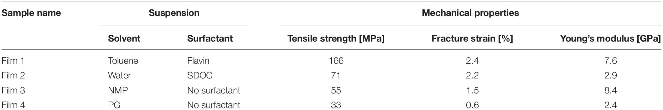
Table 1. Four types of CNT films prepared using four types of suspensions and their mechanical properties by tensile test – tensile strength, fracture strain, and Young’s modulus.
Details of the procedures we used for CNT film characterization—tensile testing, scanning electron microscopy (SEM), sheet resistance measurement, mercury porosimetry, gas adsorption, CNT film thickness measurement, Raman spectroscopy, thermogravimetric analysis (TGA), and CNT suspension characterization (by flow image analysis) are provided in the Supplementary Material.
Results and Discussion
Manufacturing of Free-Standing CNT Films and Mechanical Properties
Our fabrication process is designed to be scalable, easy, and versatile, showing compatibility to various types of substrates and solvents. We fabricated our suspension blade-coated CNT films on 4-inch wafer scale (Figures 1A,B) and as 10-cm-square free-standing samples with <200 nm thickness (Figures 1C,D). As shown in Figure 1D, our free-standing films are translucent and uniform in appearance without agglomerates over the entire span of the membrane. Optical microscopy images of the freestanding films also suggest that the film is uniform at the microscale (Figure 1E). Among the 4 types of samples prepared (Table 1), free-standing films with submicrometer thickness and >10 cm in size could only be obtained from CNT/flavin/toluene suspensions (film 1). Samples other than film 1 ruptured during the transfer process, suggesting that film 1 is more suitable for applications requiring free-standing films, such as switching/sensing elements in MEMS or ultrafiltration membranes.
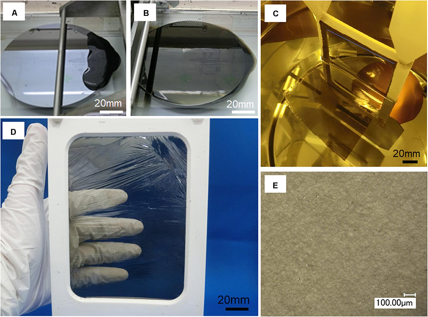
Figure 1. (A,B) Photograph of the CNT suspension blade-coating process, (C) photograph of the CNT film transfer process, and (D,E) photograph and optical micrograph of a free-standing CNT film.
Differences in transferability observed for the four types of samples stem from differences in the CNT film mechanical properties. It should be noted that film 1 showed markedly better mechanical properties than the other samples (films 2–4). Figure 2, which shows the stress-strain curves of the CNT films, indicates that film 1 shows the highest tensile strength (166 MPa), fracture strain (∼2.4%), and Young’s modulus (7.6 GPa) among the four samples. The tensile strength, fracture strain, and Young’s modulus of each sample calculated from the stress-strain curve (summarized in Table 1) show distinct differences in mechanical performances of the four samples. Film 1 shows nearly three times higher tensile strength than the other three samples (films 2–4). With regard to fracture strains, films 1 and 2 show similar values - nearly 1.5 times the values shown by the other two samples (films 3 and 4). In terms of Young’s modulus, films 1 and 3 show similar values, which are more than twice the values shown by the other two films (films 2 and 4). We think the different mechanical properties observed are related to differences in the bundle and pore structures of each sample. Therefore, we systematically characterized and studied the influence of these structural factors. The results of the film structure characterization and their correlation to the mechanical performances are presented below.
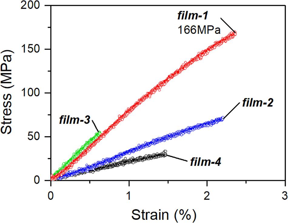
Figure 2. Tensile stress-strain curves of the CNT films.
We note that the tensile strength of film 1 (166 MPa) is comparable to thin free-standing films obtained by dry process (Zhang et al., 2005; Ma et al., 2007; Liu et al., 2011; Nasibulin et al., 2011; Zhou et al., 2012). The mechanical robustness of film 1 contributes to free-standing film fabrication in two ways.
1. It helps the film support its own weight, making free-standing submicrometer-thick samples possible.
2. It maintains film integrity during lift-off in the wet-process protocol.
We also measured film sheet resistances (film 1: 18.2 ± 1.9Ω, film 2: 18.3 ± 0.4Ω, film 3: 14.6 ± 1.1Ω, and film 4: 18.1 ± 1.7Ω). Since the values are similar and do not show a clear correlation with the film structure, we focused only on the mechanical properties.
Characterization of the CNT Film Mesh Structure
As reported in previous papers (Sakurai et al., 2018), bundled CNTs entangle in blade-coated CNT films, forming a mesh structure. Two factors could affect the film strength: (A) mesh structure of CNT bundles constituting the film (including attributes such as bundle thickness and inter- and intra-bundle pore sizes) and (B) characteristics of the CNTs themselves (such as length, diameter, wall number, crystallinity, functionalization level, etc.). In this paper, we fixed factor (B) by using identical CNT starting materials and processing methodology (sonication-based dispersion and blade-coating) for fabricating all our film samples. Our CNTs are typically single-walled nanotubes (average wall number ∼1.2), 100–300 μm in length, and 1–5 nm in diameter (average ∼3.7 nm) (Kobashi et al., 2019). Therefore, we assume that CNT attributes in our samples are comparable, which is supported by the similar Raman G/D ratios of our films (0.9, 1.9, 2.2, and 2.3, respectively, for films 1–4). Hence, we have attempted to explain the exceptional tensile strength of film 1 compared to the rest of the samples based on differences in the CNT bundle mesh structure. We characterize the mesh structure of the four films through relative standard deviation (RSD) of bundle thicknesses measured by SEM, Brunauer-Emmett-Teller (BET)-specific surface area (SSA) by gas adsorption analysis, bulk density, and G/D ratio by Raman spectroscopy (summarized in Table 2).
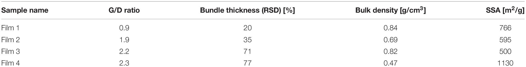
Table 2. RSD of bundle thickness measured by SEM, SSA by gas adsorption analysis, bulk density, and G/D ratio by Raman spectroscopy of the four types of CNT films prepared using four types of suspensions.
Our analysis of the mesh structure indicates that film 1 shows narrower bundle thickness and pore-size distributions than the other samples, which could contribute to the high mechanical strengths observed. Figure 3 compares the mesh structure uniformity of the strongest and weakest CNT films (films 1 and 4, respectively) in terms of SEM images and bundle thickness distribution. The CNTs are randomly aligned in both samples, which is typical for CNTs in films prepared by wet process. However, film 1 shows smaller bundles with a narrower thickness distribution (bundle thickness 10–90th percentiles: 7–11 nm, RSD: 20%) than film 4 (bundle thickness 10–90th percentiles: 19–109 nm, RSD: 77%). Consequently, film 1 contains CNT bundles of similar thicknesses forming a dense mesh with similar-sized small pores distributed uniformly throughout (Figure 3a). This narrow bundle thickness distribution of film 1 is a key feature contributing to its structural uniformity and, hence, high strength. In contrast, in film 4 (Figure 3b), bundles of various sizes entangle to result in pores of different dimensions. The presence of bundles of various thicknesses usually leads to the formation of macropores, which reduces structural uniformity and thereby lowers film mechanical strength as observed in film 4.
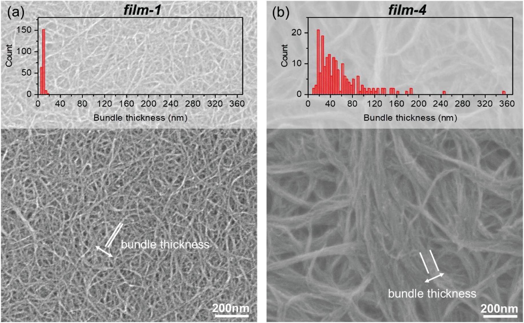
Figure 3. SEM image and CNT bundle thickness distribution of (a) film 1, (b) film 4.
Quantitative pore size distributions obtained by mercury porosimetry support SEM results on the presence of smaller pores with more size uniformity in film 1 compared to film 4 (Figure 4). Figure 4, which plots pore volume (normalized by sample weight) versus pore diameter, shows that film 1 contains fewer pores of sizes >300 nm compared to film 4. The widths of the pore volume versus diameter plots can be used as a measure of the pore-size distribution and uniformity. Film 1 shows a smaller pore volume versus diameter plot width than film 4, indicating higher pore-size uniformity in film 1 than film 4. The overall structural uniformity of film 1 (arising from similarly sized pores and bundles) enables even stress distribution, precluding stress concentration, leading to high tensile strength.
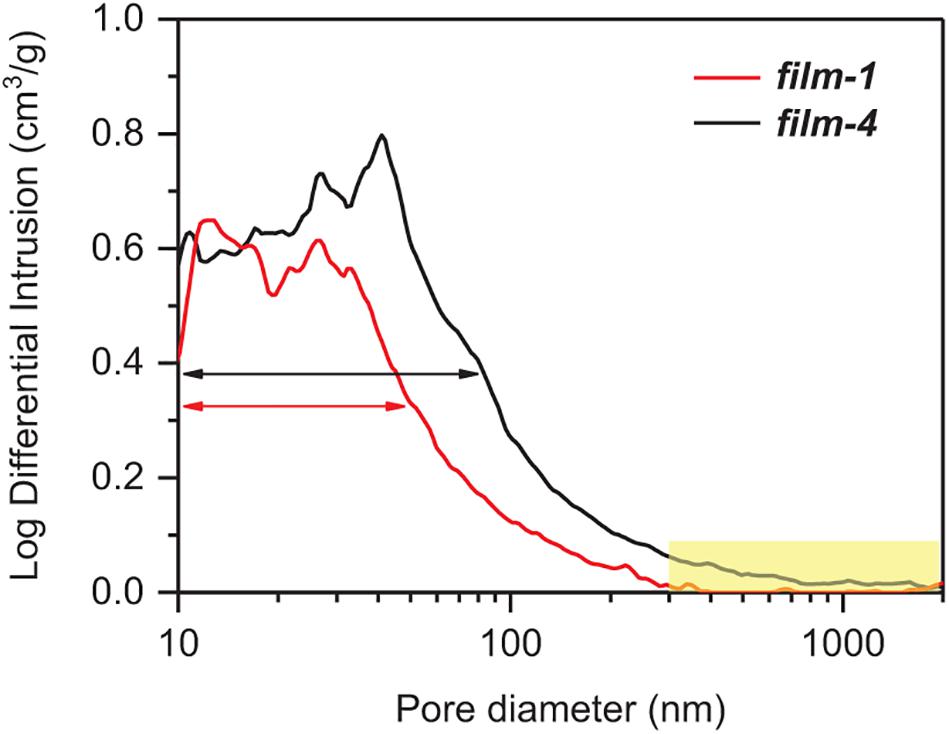
Figure 4. Pore-size distribution of films 1 (red) and 4 (black) measured by mercury porosimetery.
In addition to structural uniformity, bulk density is a well-known factor affecting mechanical strength: the higher the density, the better the CNT packing and stress transfer and the higher the tensile properties (Ma et al., 2007; Jiang et al., 2011; Zhou et al., 2012). In addition to better structural uniformity, film 1 also has a higher bulk density (0.84 ± 0.06 g/cm3) than film 4 (0.47 ± 0.14 g/cm3), which additionally contributes to the higher strength values observed. We emphasize that the mesh structure uniformity in terms of bundle thickness and pore-size uniformity more profoundly affects film mechanical strength than the bulk density. The sample with high bulk density (film 3, 0.82 ± 0.12 g/cm3) shows a much lower mechanical strength than film 1. We attribute this to the mesh structure of film 3, which, similar to film 4, is non-uniform with diverse bundle thicknesses and pore sizes (bundle thickness 10–90th percentiles: 19–111 nm, RSD: 71%) (see Supplementary Figure S1).
The structure and performance of film–2 also support that structural uniformity is important for film robustness. Film–2 shows similar mesh–structures as film 1 (see Supplementary Figure S1). The bundle thickness distribution for film 2 (bundle thickness 10–90th percentiles: 8–19 nm, RSD: 35%) is comparable to that for film 1 (bundle thickness 10–90th percentiles: 7–11 nm, RSD: 20%). Although film 2 (strength: 71 MPa) is weaker than film 1 (strength: 166 MPa), film 2 is stronger than film 4 (strength: 33 MPa) and film 3 (strength: 55 MPa). The discrepancy in the film strengths between films 1 and 2 indicates other factors are in play, affecting mechanical robustness. The poor tensile performance of film 2 can be explained based on two factors. First, film 2 shows a smaller bulk density (0.69 ± 0.10 g/cm3) than film 1 (0.84 ± 0.06 g/cm3), which translates to poorer CNT packing and stress transfer. Second, film 2 might contain a higher amount of residual surfactant (SDOC), which essentially acts as defects and, therefore, stress centers, undermining the tensile performance of the sample. We observed 8.6 wt% of TGA (air) residue for film 2 (see Supplementary Figure S2). On the other hand, very little residual flavin is left as residue in film 1. We recovered and detected at least 99% of flavin in rinsing solutions, as confirmed by ultraviolet-visible spectrophotometery (see Supplementary Figure S3). In addition, the virtual absence of residual surfactant may also be attributed to the higher (more than two times) Young’s modulus of film 1 compared to film 2. However, it should be also noted that Young’s modulus is different between film 3 and film 4 by more than two times despite similar mesh structures and being unaffected by surfactant residues. This suggests that CNT packing is more important for Young’s modulus than uniformity. In fact, gas adsorption/desorption isotherm analyses (see Supplementary Figure S4 and Table 2) indicate that film 4 contains more micropores and shows higher SSA compared to film 3, suggesting that the existence of inter- or intra-bundle pores is an important factor affecting the Young’s modulus of the CNT films.
Finally, the correlation of CNT film mechanical properties with mesh-structure uniformity and CNT packing is summarized in Figure 5. Figure 5 plots the tensile strength, fracture strain, Young’s modulus versus bundle size distribution and bulk density for the four types of samples. These figures show a clear dependence of tensile strength and fracture strain on bundle size distribution, which represents network structure uniformity. This suggests that controlling bundle size and, therefore, bundle and pore structures leads to five-fold and four-fold higher tensile strengths and fracture strains, respectively, compared to films with more bundle size variation. On the other hand, Young’s modulus depends more on bulk density, which represents the number of pores and degree of CNT packing. Therefore, films with higher bulk density with better CNT packing show three-fold higher Young’s modulus than those with the least packing (and, therefore, bulk density).
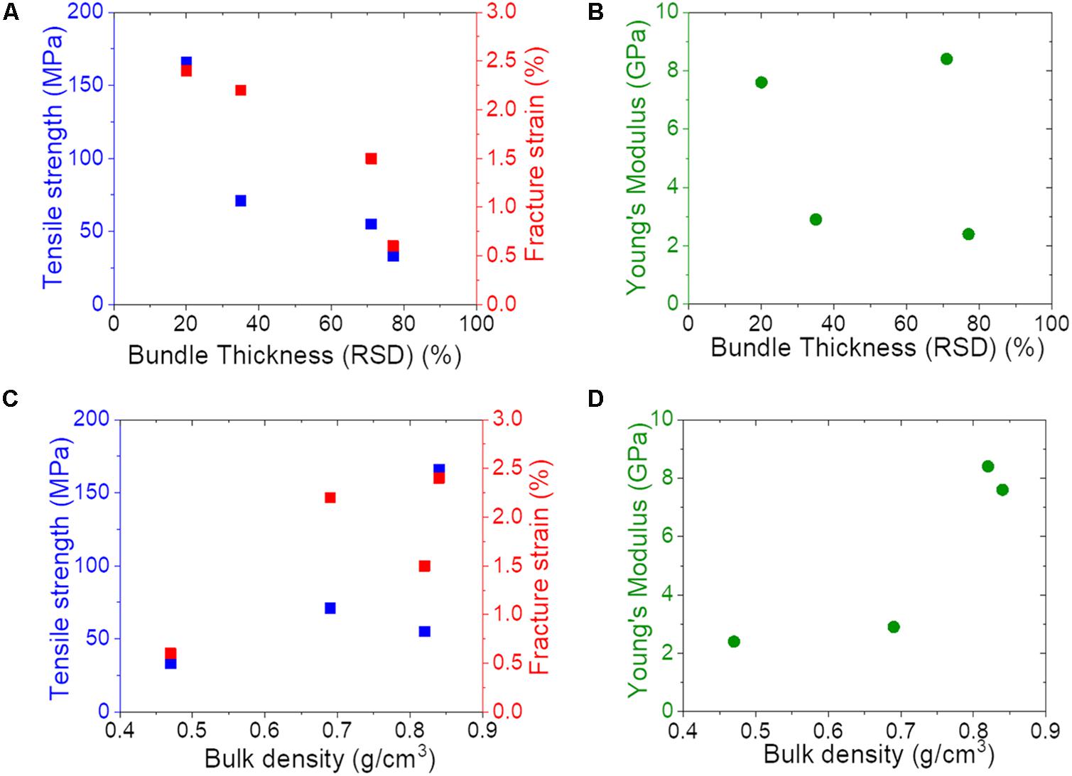
Figure 5. Plots correlating mechanical strength and bundle network structure. (A,C) Tensile strength (blue), fracture strain (red), and (B,D) Young’s modulus (green) versus bundle thickness distribution and bulk density of the CNT films.
We believe that the differences in film mesh structures observed are related to differences in the CNT aggregate sizes and their distributions in the parent suspensions. Suspending CNTs in a liquid medium by ultrasonication is typically known to result in nanotube bundle agglomerations of sizes ranging to tens of microns (Kobashi et al., 2013; Sakurai et al., 2018). These aggregates, in turn, form higher order structures, (Kobashi et al., 2013) such as our films, when suspensions are processed by techniques such as blade-coating, drop-casting, etc. We observe clear differences in CNT aggregate size distributions of the different suspensions we made for film fabrication as seen in the number frequency versus aggregate size plots (Figure 6). The parent suspensions of films 1 and 2 show a noticeably higher number fraction (>95%) of smaller aggregates (<10-micron-diameter) than that observed in the parent suspensions of films 3 and 4 (78.1 and 54.5%, respectively). The higher fraction of smaller aggregates in parent suspension 1 and 2 is indicative of superior nanotube debundling during the dispersion process, which leads to smaller and uniform-sized CNT bundles that ultimately result in the uniform mesh-structured films 1 and 2. The superior debundling of suspensions 1 and 2 can be attributed to the presence of a surfactant, i.e., flavin and SDOC, respectively, that are known to stabilize CNT aggregates and prevent their agglomeration by strong steric/electrostatic repulsions. In contrast, suspensions 3 and 4 are made without a surfactant by sonicating CNT powders in a neat solvent (i.e., PG and NMP, respectively) that stabilize the aggregates only by weak solvation effects. To sum up, well-stabilized CNT suspensions with a large fraction of small aggregates are key to making films with highly uniform mesh structures, in turn, vital to achieving high film mechanical strengths. Therefore, our study draws a holistic connection between the suspension quality, mesh structure of the films obtained, and their mechanical performances. We believe this bottom-up tailoring of robust free-standing ultrathin CNT films by wet-process blade-coating demonstrated here provides a pathway to the nanocarbon community for custom-building free-standing high-performance films of required properties. For instance, our work could be extended to CNTs with any predefined set of attributes (wall numbers, diameters, chirality, lengths, etc.) to improve electrical performances, optical properties, and so on because the suspension technique and bladed-coating can be adapted to various CNTs easily.
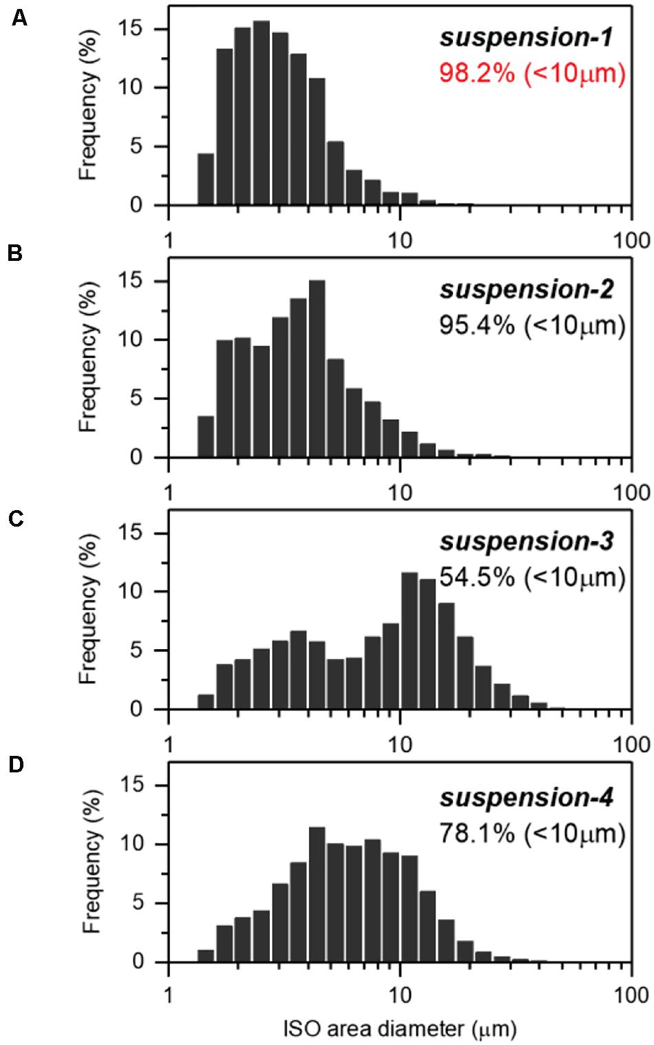
Figure 6. Size distribution of CNT aggregates measured by flow image analyzer of (A), suspension 1, (B) suspension 2, (C) suspension 3, (D) suspension 4.
Conclusion
In summary, we fabricated large (10-cm-square) 200-nm-thick free-standing robust CNT films by a scalable, wet process involving blade-coating of CNT/surfactant suspensions. We demonstrate that a uniform mesh structure with narrow bundle and pore size distribution is vital to achieving robust thin films with strengths as high as 166 MPa. Further, we correlate the mesh structure with CNT aggregate sizes (and its distribution) in the parent suspension. We find that well-stabilized suspensions using surfactants with higher fractions of smaller aggregates lead to CNT films with uniform mesh structures that exhibit high mechanical performances. Our work presents a bottom-up approach of tailoring robust ultrathin free-standing CNT films by wet process through a versatile and potentially scalable fabrication methodology.
Data Availability Statement
The raw data supporting the conclusions of this article will be made available by the authors, without undue reservation.
Author Contributions
YK performed sample preparation, measurement, and analysis. YK and AS conceived the idea and designed the experiments. KK contributed to flow image analysis. YK, AS, and RS prepared the draft of the manuscript. TY and KH conceived the idea and supervised the project. All authors contributed to the article and approved the submitted version.
Conflict of Interest
The authors declare that the research was conducted in the absence of any commercial or financial relationships that could be construed as a potential conflict of interest.
Acknowledgments
We thank Dr. T. Morimoto and Dr. T. Okazaki for useful discussion. M. Nishimura, R. Shiina, F. Kamada, K. Miura, M. Fujii, and S. Nemoto are acknowledged for their technical support.
Supplementary Material
The Supplementary Material for this article can be found online at: https://www.frontiersin.org/articles/10.3389/fmats.2020.562455/full#supplementary-material
References
Gu, H., and Swager, T. M. (2008). Fabrication of free-standing, conductive, and transparent carbon nanotube films. Adv. Mater. 20, 4433–4437. doi: 10.1002/adma.200801062
Hata, K., Futaba, D. N., Mizuno, K., Namai, T., Yumura, M., and Iijima, S. (2004). Water-assisted highly efficient synthesis of impurity-free single-walled carbon nanotubes. Science 306, 1362–1364. doi: 10.1126/science.1104962
Hecht, D. S., Hu, L., and Irvin, G. (2011). Emerging transparent electrodes based on thin films of carbon nanotubes, graphene, and metallic nanostructures. Adv. Mater. 23, 1482–1513. doi: 10.1002/adma.201003188
Hu, L., Hecht, D. S., and Grüner, G. (2010). Carbon nanotube thin films: fabrication, properties, and applications. Chem. Rev. 110, 5790–5844. doi: 10.1021/cr9002962
Ibañez, D., Garoz-Ruiz, J., Plana, D., Heras, A., Fermín, D. J., and Colina, A. (2016). Spectroelectrochemistry at free-standing carbon nanotubes electrodes. Electrochim. Acta 217, 262–268. doi: 10.1016/j.electacta.2016.09.074
Janas, D., and Koziol, K. K. (2014). A review of production methods of carbon nanotube and graphene thin films for electrothermal applications. Nanoscale 6, 3037–3045. doi: 10.1039/c3nr05636h
Janas, D., Rdest, M., and Koziol, K. K. (2017). Free-standing films from chirality-controlled carbon nanotubes. Mater. Des. 121, 119–125. doi: 10.1016/j.matdes.2017.02.062
Jiang, K., Wang, J., Li, Q., Liu, L., Liu, C., and Fan, S. (2011). Superaligned carbon nanotube arrays, films, and yarns: a road to applications. Adv. Mater. 23, 1154–1161. doi: 10.1002/adma.201003989
Jo, J. W., Jung, J. W., Lee, J. U., and Jo, W. H. (2010). Fabrication of highly conductive and transparent thin films from single-walled carbon nanotubes using a new non-ionic surfactant via spin coating. ACS Nano 4, 5382–5388. doi: 10.1021/nn1009837
Ju, S.-Y., Kopcha, W. P., and Papadimitrakopoulos, F. (2009). Brightly fluorescent single-walled carbon nanotubes via an oxygen-excluding surfactant organization. Science 323, 1319–1323. doi: 10.1126/science.1166265
Kato, Y., Fukuzawa, M., Toshimitsu, F., and Nakashima, N. (2015). Separation of semiconducting single-walled carbon nanotubes using a flavin compound. Chem. Lett. 44, 566–567. doi: 10.1246/cl.141193
Kobashi, K., Ata, S., Yamada, T., Futaba, D. N., Okazaki, T., and Hata, K. (2019). Classification of commercialized carbon nanotubes into three general categories as a guide for applications. ACS Appl. Nano Mater. 2, 4043–4047. doi: 10.1021/acsanm.9b00941
Kobashi, K., Ata, S., Yamada, T., Futaba, D. N., Yumura, M., and Hata, K. (2013). A dispersion strategy: dendritic carbon nanotube network dispersion for advanced composites. Chem. Sci. 4, 727–733. doi: 10.1039/C2SC21266H
Liu, K., Sun, Y., Liu, P., Lin, X., Fan, S., and Jiang, K. (2011). Cross-stacked superaligned carbon nanotube films for transparent and stretchable conductors. Adv. Funct. Mater. 21, 2721–2728. doi: 10.1002/adfm.201100306
Liu, Q., Fujigaya, T., Cheng, H.-M., and Nakashima, N. (2010). Free-standing highly conductive transparent ultrathin single-walled carbon nanotube films. J. Am. Chem. Soc. 132, 16581–16586. doi: 10.1021/ja1067367
Ma, W., Song, L., Yang, R., Zhang, T., Zhao, Y., Sun, L., et al. (2007). Directly synthesized strong, highly conducting, transparent single-walled carbon nanotube films. Nano Lett. 7, 2307–2311. doi: 10.1021/nl070915c
Nasibulin, A. G., Kaskela, A., Mustonen, K., Anisimov, A. S., Ruiz, V., Kivistö, S., et al. (2011). Multifunctional free-standing single-walled carbon nanotube films. ACS Nano 5, 3214–3221. doi: 10.1021/nn200338r
Parhi, P. K. (2013). Supported liquid membrane principle and its practices: a short review. J. Chem. 2013, 1–11. doi: 10.1155/2013/618236
Sakurai, S., Kamada, F., Kobashi, K., Futaba, D. N., and Hata, K. (2018). A new, general strategy for fabricating highly concentrated and viscoplastic suspensions based on a structural approach to modulate interparticle interaction. J. Am. Chem. Soc. 140, 1098–1104. doi: 10.1021/jacs.7b11305
Shi, Z., Chen, X., Wang, X., Zhang, T., and Jin, J. (2011). Fabrication of superstrong ultrathin free-standing single-walled carbon nanotube films via a wet process. Adv. Funct. Mater. 21, 4358–4363. doi: 10.1002/adfm.201101298
Sreekumar, T. V., Liu, T., Kumar, S., Ericson, L. M., Hauge, R. H., and Smalley, R. E. (2003). Single-wall carbon nanotube films. Chem. Mater. 15, 175–178. doi: 10.1021/cm020367y
Wang, H., and Bao, Z. (2015). Conjugated polymer sorting of semiconducting carbon nanotubes and their electronic applications. Nano Today 10, 737–758. doi: 10.1016/j.nantod.2015.11.008
Zhang, M., Fang, S., Zakhidov, A. A., Lee, S. B., Aliev, A. E., Williams, C. D., et al. (2005). Strong, transparent, multifunctional, carbon nanotube sheets. Science 309, 1215–1219. doi: 10.1126/science.1115311
Keywords: carbon nanotube, free-standing film, tensile strength, fracture strain, bundle thickness, pore size
Citation: Kato Y, Sekiguchi A, Kobashi K, Sundaram R, Yamada T and Hata K (2020) Mechanically Robust Free-Standing Single-Walled Carbon Nanotube Thin Films With Uniform Mesh-Structure by Blade Coating. Front. Mater. 7:562455. doi: 10.3389/fmats.2020.562455
Received: 15 May 2020; Accepted: 14 August 2020;
Published: 08 October 2020.
Edited by:
Ming Xu, Huazhong University of Science and Technology, ChinaReviewed by:
Qingwen Li, Suzhou Institute of Nano-Tech and Nano-Bionics (CAS), ChinaRenyuan Zhang, Tongji University, China
Copyright © 2020 Kato, Sekiguchi, Kobashi, Sundaram, Yamada and Hata. This is an open-access article distributed under the terms of the Creative Commons Attribution License (CC BY). The use, distribution or reproduction in other forums is permitted, provided the original author(s) and the copyright owner(s) are credited and that the original publication in this journal is cited, in accordance with accepted academic practice. No use, distribution or reproduction is permitted which does not comply with these terms.
*Correspondence: Atsuko Sekiguchi, YXRzdWtvLXNla2lndWNoaUBhaXN0LmdvLmpw