 Yajie Feng1
 Jun Wang1,2
 Nianwei Shang1,3Gang Zhao1,4Chao Zhang1Jianbo Tang1,5Shiqing Xin5
 Andreas Hornig3Maik Gude3Qing Huang1,2Xigao Jian4Jian Xu1,2,4*
- 1Engineering Laboratory of Advanced Energy Materials, Ningbo Institute of Material Technology & Engineering, CAS, Ningbo, China
- 2University of Chinese Academy of Sciences, Beijing, China
- 3Institute of Lightweight Engineering and Polymer Technology, Technische Universität Dresden, Dresden, Germany
- 4State Key Laboratory of Fine Chemicals, Liaoning High Performance Polymer Engineering Research Center, School of Chemical Engineering, Dalian University of Technology, Dalian, China
- 5School of Computer Science and Technology, Shandong University, Qingdao, China
A generalized multiscale (micro-macro) finite element (FE) model for SiC-fiber reinforced SiC-matrix ceramic (SiCf/SiC) nuclear fuel claddings is established. In the macro level, the solid mesh of braided preform, which can be tailored by machine settings (braid angle, yarn width, and so on), is generated based on the braiding process simulation using the dynamic FE-solver, hiring the contact constraints. The matrix mesh and the yarn mesh are integrated by the embedded region constraint, with which the meshing difficulties can be avoided. In the micro-UD model, the progressive damage of the ceramic matrix is modeled using the phase field method (PFM) and the fracture is captured by Mohr–Coulombs criterion, which are stable and efficient in the description of the brittle crack initiation, coalition, and branching. Based on this multiscale model, the mechanical behavior of the braided SiCf/SiC nuclear fuel cladding tube is studied in detail. The superiorities over the homogenized tube model are demonstrated, too.
Introduction
The continuous SiC-fiber reinforced SiC-matrix composites (SiCf/SiC) have been applied to high temperature applications such as aerospace propulsion systems (Naslain, 2004). With the assistance of tailored fibrous reinforcement, the SiCf/SiC composites possess pseudoductility, which can efficiently redirect the way of crack propagation, and are highly demanded by nuclear structures under critical service circumstances. Hence those “toughened” ceramic composites are gaining their popularities in the research and application as structural materials of nuclear fuel claddings (Figure 1A)) in advanced reactor designs (Riccardi et al., 2004; Snead et al., 2011; Hallstadius et al., 2012; Yueh and Terrani, 2014). To finalize the radiation-resistant fuel claddings, the dedicated processes, e.g., eutectic-phase sintering (NITE) and chemical vapor infiltration (CVI), are used to produce the high purity matrix (Deck et al., 2012; Chaâbane et al., 2013; Katoh et al., 2014).
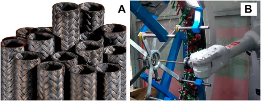
FIGURE 1. The 2D braiding technique for nuclear claddings. (A) The ceramic cladding based on 2D braided preform. (B) The six axis robot aided braiding process.
Provided with certain properties of the constituent materials, the SiCf/SiC properties are strongly dependent on the fibrous reinforcements, e.g., fiber volume fraction, fiber orientation, and the fiber architecture. Most of the time, the adequate fiber volume fraction can be achieved with refined processing techniques. Therefore, the design of the fibrous architecture, as well as the fiber orientation, will be crucial to enhance the comprehensive mechanical properties of the tubular claddings (Katoh et al., 2014). Sauder (Sauder, 2014) has experimentally investigated the properties of the SiCf/SiC claddings produced using filament winding, 2D braiding (Figure 1B) and 3D braiding techniques, which are the most appropriate processing techniques for the manufacturing of parts with an axis of rotation (fuel cladding, control rods, etc.). He found that the 2D and 3D braided textures provide greater mechanical properties, e.g., break stress and break strength, than that of winded ones for equivalent fiber angles and similar volume fractions. However, the 3D braided tube has a limitation of lower fiber volume fraction (Vf < 40%), due to the higher porosities that are the key factor hindering the thermal conductivity, than that of the 2D braided one (Vf ∼50%). Consequently, the 2D braiding process is the optimal processing technique to manufacture the reinforcement of the claddings.
The 2D braiding process is suitable for automated manufacturing and allows for an economic and rapid preforming process for nuclear structures. Against this background, it lacks an efficient design process that considers the specific processing parameters. The coverage rate, braiding angle, areal weight, etc., of the braid laminate properties are highly dependent on the machine parameters. Trial-and-error is hardly affordable for ceramic composite than resin-based composite because of the tremendous material cost. Hence the gap between the laminate properties and machine parameters must be bridged using a numerical processing model. Based on this process model, the fiber architecture can be clearly determined and, thereafter, the mechanical properties of the tubular structure can be optimized and precisely predicted (Pickett et al., 2009a).
Since early 1990s, the analytical model (Rosenbaum, 1991) and kinematic models (Kessels and Akkerman, 2002) were established. The analytical model provides an acceptable prediction of the braiding angle. However, it can only apply to axisymmetric core geometries. This issue was indeed solved by the kinematic model. Nevertheless, the kinematic model has a strong simplification that neglects interaction between yarns and mandrel, e.g., friction and compression. Thus, the yarn undulation, slippage, reorientation, and densification, which are indispensable for structure optimization, cannot be correctly reproduced. To fulfill the requirements in the maximum extent, the 2D braiding model based on finite element method was proposed by Pickett (Kessels and Akkerman, 2002), where the friction and compression between yarns and mandrel are possibly represented by using the contact constraints. One weakness of his model yet would be the missing cross-section of the yarn that defines the spatial occupation of the reinforcement and the contact surface, as well as the bending properties of the yarns. The bar element was used in the braiding simulation intending to speed up the process. Generally, those cross-sectional parameters crucially affect the final pattern of the preform in terms of friction and waviness. Although Pickett has improved his work by coupling with a representative volume element (RVE) model that uses the solid elements and possesses the same fiber path as the braided fabric (Pickett et al., 2009b), the deviation of the simulation in braiding cannot be retrieved. In our work, the solid elements are used directly in the braiding process that can physically reflect the mechanical behavior of yarns during the braiding process and, thus, the waviness of the impregnated yarn in the structure.
Besides a physical-based geometrical mesh, the mechanical prediction of the ceramic cladding tubes necessitates the multiscale modeling techniques, too. Different from fiber-resin composite, the current ceramic composites have neither a well-established material property design database nor a validated micromechanical analysis methodologies (Mital et al., 2009), such as the Chamis’ equations (Chamis, 1983; Chamis, 1984). The transversal yarn properties, which are necessitated as the inputs of the tube simulation, are strenuous to evaluate based on mechanical tests. Fortunately, the computational micromechanics (Vajari et al., 2014; Vajari, 2015) has provided an effective way to calculate the transverse and shear behavior of unidirectional SiCf/SiC ceramics based on RVE models. The mechanical properties on the fiber direction can be easily calculated using the rule of mixture. Eventually, the calculated properties are used as input parameters of the macro model, e.g., the yarns of the braided tube model (Xu et al., 2014; Xu et al., 2015).
In this article, a new multiscale modeling method for SiCf/SiC claddings based on FE simulation of braiding process is proposed. To capture the detailed mechanical behavior of the yarns during the braiding process, the solid elements (C3D8R) are used to mimic the yarns, of which the friction, compression, slippage, and densification can be reproduced using FE contact constraints. The numerically braided preforms are, thereafter, applied to the structural analysis, assigned with the material properties that are evaluated by using micro-UD models in transverse tension, compression, and shear. The microvoids, which are often observed in ceramic composites, are accounted for the micromechanical property calculations (Wang et al., 2020). Another advantage of the RVE model would be that the pyrocarbon interface between fiber and matrix is modeled, too. The tension and torsion forces are applied to the tubes. The apparent properties are compared to that of the tubes simplified by using laminates. It was revealed that the laminated tube, which was often adopted as the replacement of the braided tube in design, has remarkable deviations in the prediction of the global properties, in terms of strengths. The deviations are caused by the stress concentrations introduced by the waviness of the yarns as stated in the references (Xu et al., 2014; Xu et al., 2015).
Our work is dedicated to establish an efficient virtual tool for the design of the ceramic composite claddings, whose reinforcements are produced using braiding technique. The multiscale models are used to physically bridge the gap between constituents and tubular structures with the upwards transmission of material parameters. Comparison of the numerical results between braided tubes and laminated tubes has clearly exhibited that the latter models are insufficient for structural design. Under such circumstance, a more realistic braided tube model, as well as a multiscale modeling roadmap, would be crucial for the design of fuel claddings. The advantages of the virtual tool are as follows.
1. The fiber path, as well as the derived 3D mesh, of the cladding tube is physically based. It can be customized according to the real production parameters. The effects of the fiber friction, fiber compression, fiber tension, etc. can be taken into consideration.
2. The mechanical properties of the yarn-matrix can be calculated using micro model, where the random distribution of the fiber and voids can be accounted. The fiber-matrix interface that is one of the crucial constituents for fibrous ceramic composite can be modeled.
3. The phase field cohesive zone method, which is able to model the brittle crack propagation, is implemented in the Abaqus® User-defined Material (UMAT) for the ceramic matrix material. Thanks to this method, the convergence of the model is highly improved.
Thanks to the physical-based multiscale model, the apparent moduli of the braided tubes under tensile and torsional loads are predicted and validated by laminated tubes and microscale RVEs. The comparisons of the moduli show good agreements. Moreover, the local stresses are analyzed in detail, and the braided tube exhibits lower strength owing to the yarn waviness. It again demonstrated that our modeling strategy is indispensable in the design phase of the nuclear cladding tubes, as well as other structural ceramic composites.
FE-Based Braiding Process Simulation
Governing Equation of FEM
In order to handle large geometric deformations and massive contact problems that constantly occur during the fiber placement, the simulation of the braiding process is performed based on the explicit solver built in Abaqus software. The key issue is to numerically solve a dynamic equation that contains nodal kinetic unknowns and nodal mass, as well as material properties. The nodal dynamic equations are as follows:
where
where the
Intentionally, the flat solid elements C3D8R are used as “yarn” to occupy the space, reproducing the compression, bending stiffness, and thus waviness in a reasonable way. To balance the computational effort and quality, the single yarn is modeled using six elements along the width direction. The yarn width and thickness are 2 and 0.01 mm, respectively. The moduli along the fiber direction and transverse direction are 380 and 1 GPa. The latter value should be properly provided to reproduce the softness of the yarn without convergence difficulty. The mandrel and guide ring are described by shell elements with rigid behavior. The bobbins are replaced by nonlinear springs to provide a constant tension of 3N simulating the tension in the yarn and stabilize the calculation. According to the experiment (Pickett et al., 2009a), the yarn-yarn and tool-yarn friction coefficients are 0.189 and 0.432, respectively.
Periodical Displacement of Bobbing
The braid angle is defined as the angle between the longitudinal axis and the braided yarns. For a cylindrical mandrel, the angle can be evaluated through the following equation (Kyosev, 2014):
where
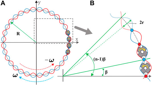
FIGURE 2. The schematic path of the bobbin movement. (A) There are totally 32 bobbins revolving around the mandrel in the bobbin planes with a diameter of 2R. With the angular speed of ω, half of them are moving clockwise, while the other half are moving anticlockwise. The two groups of yarns interlock, forming a biaxial fabric. Approximately, the actual path of a bobbin fits a sinusoidal. (B) The position and displacement of a certain bobbin is the function of β and its index n. The bobbin is driven by the horn gear that has a diameter of 2r.
Therefore, the original position of a bobbin in the bobbin plane is
while the actual position of the bobbin walking clockwise at time t can be represented as
and the one walking anticlockwise at time t is represented as
Subtracting (5) and (6) by (4) respectively, the displacement of the nth bobbin is obtained. For each of the bobbins, the displacement is rearranged into a Fourier form and the Fourier cofferents will be submitted to the Abaqus.
Braiding Simulation
Figure 3A describes the numerical investigation to the virtual production of the cladding braid. The solid mesh will be, thereafter, transferred to a structural analysis containing the real yarn architecture. The 32 braiding yarns are moving on a sinusoidal path with rotational speed of 5 rad/s Figure 2, whereas the mandrel (diameter of 12 mm) translates at a constant speed of 17.4 mm/s. The bobbins are modeled as spring elements that provide the constant tensile force to the yarns of 3.6 N. The yarns are discretized with solid elements because the obtained deformed mesh will facilitate the calculation of the out-of-plane mechanical properties of the claddings in the next step. The contact constraint is used to prevent the interpenetration of the yarns and, as well, provide a friction coefficient of 0.2. As seen in Figures 3A,C, the braiding angle is about 60°. In the structural calculation, the mesh of the yarns is integrated with the matrix mesh using the embedded element method. The main benefit of this approach is the independent meshing for the yarns and the matrix, while the full model will lead to a poor element quality in the place where thin gaps are between yarns. The volume redundancy of yarn and matrix will be manipulated by stiffness subtraction of the two materials (Tabatabaei et al., 2015).
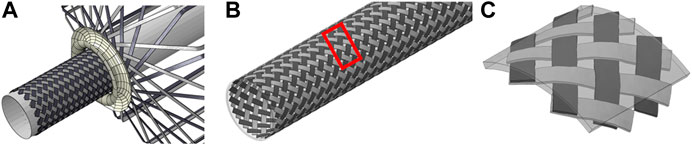
FIGURE 3. The braiding simulation of the preform for nuclear cladding. (A) The dynamic process simulation using contact constraints; (B) the braided clad; (C) the integration of preform mesh and the matrix mesh using the embedded region constraint.
Progressive Damage Model for SiCf/SiC Micro-UD
Micro-UD Model
In micro level, the 3D RVE model with periodic boundary conditions (PBCs) is developed to predict the necessitated mechanical properties, e.g., transverse tensile/compressive properties and in-plane/out-plane shear properties, of the unidirectional fiber reinforced ceramics. In the RVE model, randomly distributed SiC fibers with an average fiber diameter of 7 μm are embedded in the SiC matrix, as shown in Figure 4, and the RVE model has a dimension of 56 × 56 × 0.5 μm, which is accurate enough to capture the mechanical properties of composites (González and Llorca, 2007). Then the periodic RVE models are respectively discretized using C3D6 and C3D8 elements, and it yields 18,300 elements in total.
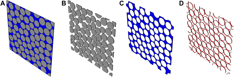
FIGURE 4. Micro-UD mode of SiCf/SiC composite: (A) random fiber distribution in RVE model with a fiber volume fraction of 70%; (B) fibers set; (C) matrix set; and (D) cohesive interfaces set with 0.001 μm thickness.
The model consists of SiC fiber, SiC matrix, and fiber/matrix interface (Figures 4B–D). The fiber in this study is modeled by a thermoelastic solid (Sauder, 2014) with 380 GPa Young’s modulus and 0.17 Poisson’s ration, while the matrix is modeled as elastic-brittle damageable solid, and the phase Field Cohesive Zone Model (PF-CZM) proposed by Wu (Wu and Nguyen, 2018) is adopted in this study to simulate the crack propagation in SiC matrix. The PF-CZM will be discussed in detail in the next subsection. As for fiber/matrix interfaces, the cohesive element is used to capture the debonding between fiber and matrix. The initial stiffness, K, of the cohesive element is set to be a large number (5,000 GPa/μm) to ensure the displacement continuity and to avoid any modification of the stress fields in the absence of damage. The interface strength and fracture energy are set equal to 50 MPa and 20 J/m2 according to Yang’s work (Yang et al., 2017).
Phase Field Cohesive Zone Method
The PF-CZM is a length scale insensitive phase-field damage model for brittle fracture (Wu, 2017; Wu and Nguyen, 2018). Compared to standard phase-field models (Pham et al., 2010), PF-CZM gives a length scale independent of the global mechanical response, which has been proven in previous literature (Wu and Nguyen, 2018).
According to the variational form of the Griffith energy (Francfort and Marigo, 1998), the formulation of phase-field methods for brittle fracture can be written as
which means the total potential energy
where E is the Young’s modulus, Gc stands for the fracture toughness, and c represents the cohesion. In order to capture tensile and compressive fracture, the Mohr–Coulombs criterion is used (Menetrey and Willam, 1995). The PF-CZM is implemented in Abaqus user-defined element (UMAT). The following material parameters of matrix (Sarva and Nemat-Nasser, 2001; Snead et al., 2007) are adopted: the Young’s modulus Em = 300 GPa, the Poisson’s ratio vm = 0.14, the tensile failure strength σt = 500 MPa, the compressive failure strength σc = 5 GPa, the fracture toughness Gm = 20 J/m2, and the internal length l = 3 μm.
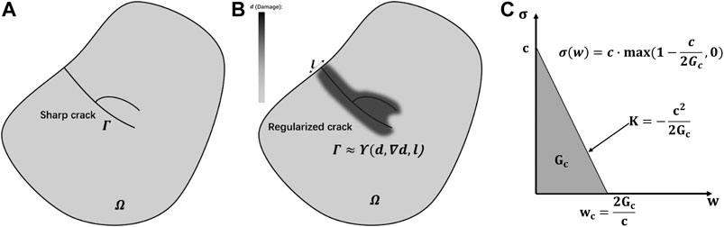
FIGURE 5. A solid medium with a sharp crack (A) and the phase-field regularization (B), and (C) illustrates the linear traction-separation law during crack propagation.
Prediction of the SiCf/SiC UD Unit Cell
Two micro-UD models with fiber volume fraction of 28 and 70%, respectively, are established to predict the basic mechanical properties, as the input material parameters for the laminates and yarns in the cladding tube calculations. The corresponding normal and shear are applied to the micro-UDs, respectively.
Figures 6, 7 show the failure of UD ceramic composite (Vf = 28% and Vf = 70%) with different loading conditions. The fiber/matrix debonding always first occurs in the densely packed fibers, and then the stress concentration in the densely packed fibers will cause damage to the SiC matrix. The results show that the existence of weak fiber/matrix interface can not only microscopically provoke crack initiation but also lead to different crack paths. The predicted mechanical properties are listed in Table 1. Compared to 28% fiber volume fraction composites, composites with 70% fiber volume fraction has lower mechanical strengths and failure strains, which is the result of the large existence of week fiber/matrix interface. However, composites with 70% fiber volume fraction have higher moduli due to the contribution of higher fiber volume fraction. The essential properties will be used as input data for the structural calculations.
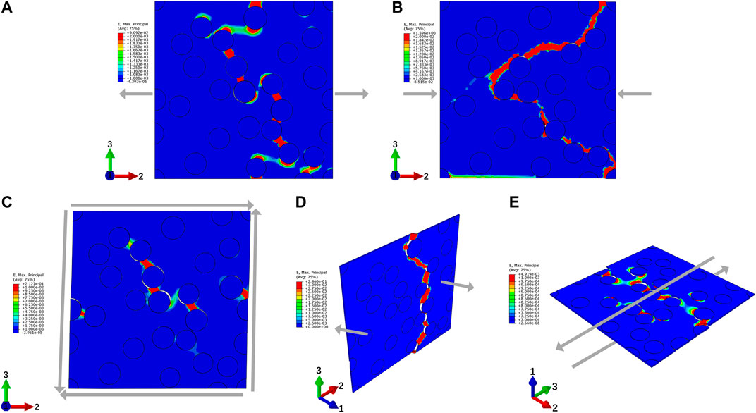
FIGURE 6. Contour plots of the accumulated strain with different loading conditions when ceramic composite (Vf = 28%) fails: (A) transverse tension, (B) transverse compression, (C) out-plane shear (
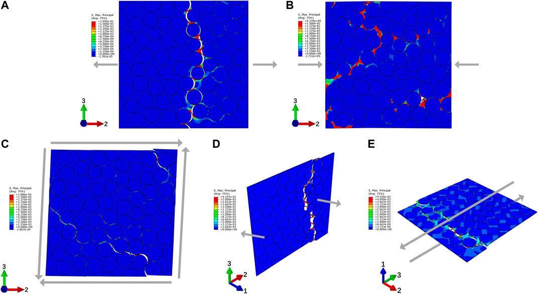
FIGURE 7. Contour plots of the accumulated strain with different loading conditions when ceramic composite (Vf = 70%) fails: (A) transverse tension with deformation magnified by a factor of 10, (B) transverse compression, (C) out-plane shear (
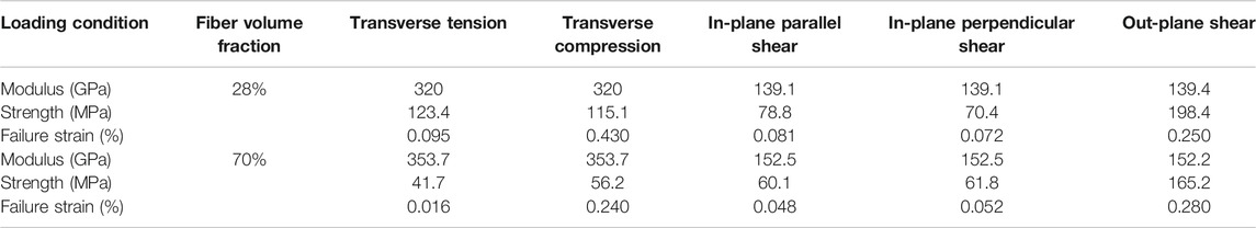
TABLE 1. The predicted tansverse fiber properties for SiCf/SiC micro-UD model.
Numerical Simulation of the Claddings
The process simulation model (FE-based Braiding Process Simulation) and micro-UD model (Progressive Damage Model for SiCf/SiC Micro-UD) have provided the mesh and material properties, based on which the structural analysis can be performed. The numerical results of the braided tube will be compared with the laminated tube that is often used as a simplification. The discrepancies of these two models will be investigated in detail.
Structural Analysis of Nuclear Cladding
As seen in Figure 8, the tube has a length of 75 mm, an external diameter of 12 mm, and a wall thickness of 0.3 mm. The two ends are coupled to two master nodes using continuum distributing constraint, which means that the external loads, either force or momentum, exerting on the master nodes are distributed to the selected nodes by weight. The braided yarns have 64,800 C3D8R elements and matrix has 28,080 elements (Figure 8B), while the laminated tube has 35,568 elements (Figure 8C). The global fiber volume fraction is 28% for both braded and laminated tubes. The input material properties are listed in Table 2, calculated from the previous section and selected from Table 1. The SiC matrix has a Young’s modulus of 300 GPa and a Poisson ratio of 0.14.
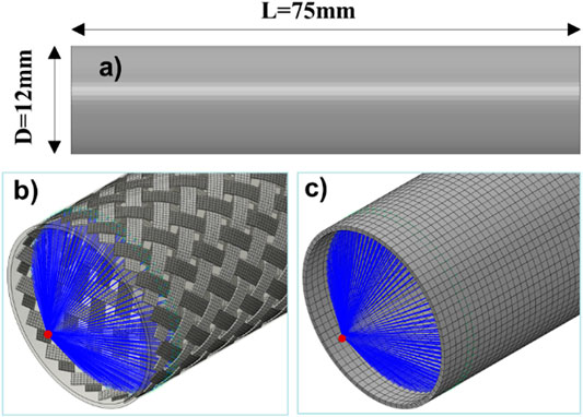
FIGURE 8. The FE model of the nuclear cladding tube: (A) the dimension of the tube with a thickness of 0.3 mm; (B) the braided mesh integrated with the matrix mesh using embedded constraint; (C) the laminated tube. The global fiber volume fractions are identical of 28%. The boundary conditions are applied to the master nodes using the continuum distributing constraints.
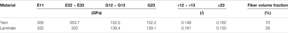
TABLE 2. Input mechanical properties for yarn and laminate, calculated from micro-UD model.
Tensile and Torsional Simulation and Validation of the Cladding
With the obtained mesh (Figure 8) and material properties (Table 2), the macro model of the cladding tube can be applied to structural optimization. Generally, the models of laminated tube with identical fiber orientations are often used to predict the major mechanical properties, e.g., apparent moduli and strengths, as a simplified substitute. However, the weakening effect of the yarn waviness and interlocks has not yet been specifically investigated in the previous work of cladding design. In the following discussion, an equivalent tensile loading will be applied to these tubes; the apparent moduli of the braided tube and laminated tube will be calculated and compared in Figure 9.
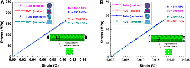
FIGURE 9. The local shear and tensile moduli of the braided and laminated tubes, validated by unit cell model. (A) The local shear under the global tensile loading; (B) the local tension-compression under the global torsional loading.
Figure 9 shows that the local shear and tensile moduli of the braided and laminated tubes are quasiequivalent. Although the local tensile modulus of the laminated tube is 311 GPa, 2% higher than that of the braided tube, the deviation is still in the tolerance. In order to further prove the accuracy of the macro model, the unit cell possessing the identical fiber volume fraction is used as a validation. The comparisons show fairly good agreements. In such a circumstance, therefore, the macro model can be used to predict the apparent moduli of the cladding tube, especially under complex service loadings.
Although the calculated moduli of the braided tube and the laminated tube present good agreement, the local stress states are totally different whereas the waviness and interlock of the yarn cause stress concentration, which will introduce an earlier damage initiation and final failure of the cladding tube. In Figure 10, the local in-plane shear stress damage factors, that is the typical stress state under tube tension, are demonstrated. The damage factor, which is defined as the ratios of the shear stress and shear strength for the braided tube yarn, of the braided tube and laminated tube outside are extracted from the nodes on the axial and hoop directions. According to our assumption, the damage factors in the braided yarns are almost 40% higher than that of the laminated tube (Figures 10B,C), which means that the damage initiation will occur somewhere in the yarn as the result of stress concentration caused by the waviness and higher local fiber volume fraction. In contrast, the matrix in the braided tube bears 46% less loading that that in the laminated tube. The shear loading state in the laminate tube is much well distributed than that in the braided tube. In such a context, with a same fiber volume fraction, the braided tube and the laminated one have similar values of shear moduli but quite different apparent strengths: the high stress concentration results in a lower strength for braided tubes. This result confirmed that a precise braiding structure on a mesolevel for property prediction of the cladding tube is inevitable.
FIGURE 10. The local shear damage factor analysis of the tube under the global tensile loadings. (A) The uniform shear local stress just before shear damage of the yarn; (B) the in-plane damage factors of the braided tube yarn, braided tube matrix, and laminated tube outside on the axial direction; (C) the in-plane damage factors of the braided tube yarn, braided tube matrix, and laminated tube on the hoop direction.
Summary and Conclusion
In this research, a multiscale model for SiCf/SiC nuclear fuel cladding based on FE-Simulation of braiding process has been established. The braiding process is parametrically simulated based on the dynamical FE-solver, of which the 3D elements are used to occupy the spaces and the mesh is, thereafter, used for structural analysis. The mechanical properties of the yarn-matrix composite, e.g. transverse tension, compression, and shear properties, are evaluated by using micro-UD models, where the fibers, fiber-matrix interfaces, matrix voids, and their random distributions can be taken into account. With the help of the outputs of the micro model, the apparent properties of the cladding tubes can be evaluated. The comparisons of the apparent properties with those of the laminated tube prove that the model of the laminated tube overestimates the structural strength. The stress concentration due to the yarn waviness that causes the earlier damage onset should be considered and optimized in the design phase by virtue of the braiding process simulation tool. Certainly, the current multiscale virtual tool can be applied to a more complex loading case for fibrous ceramic composite structures.
Data Availability Statement
The raw data supporting the conclusions of this article will be made available by the authors, without undue reservation.
Author Contributions
YF carried out investigation, methodology, data curation, software, writing-original draft preparation, visualization, and formal analysis. JW performed data curation, software, methodology, writing-reviewing, and editing. NS, GZ, and JT contributed to software and validation. AH and MG participated in validation. SX did implementation of the computer code and supporting algorithms and testing of existing code components. QH and XJ carried out project administration, supervision, and funding acquisition. JX contributed to writing-reviewing and editing, project administration, supervision, and funding acquisition.
Funding
This work was supported by the National Natural Science Foundation of China (No. 52075526). The authors also gratefully acknowledge the National Key Research and Development Program (No. 2018YFB1107500), the “Ningbo 3315 Plan Innovation Team” (No. 2017A-28-C), the “Transformational Technologies for Clean Energy and Demonstration”, the Strategic Priority Research Program of the Chinese Academy of Sciences (No. XDA21010205), and the financial support from National Young Talents Program of China.
Conflict of Interest
The authors declare that the research was conducted in the absence of any commercial or financial relationships that could be construed as a potential conflict of interest.
References
Chaâbane, N., Le Flem, M., Tanguy, M., Urvoy, S., Sandt, C., Dumas, P., et al. (2013). Au ion irradiation of various silicon carbide fiber-reinforced SiC matrix composites. J. Nucl. Mater. 439 (1–3), 123–130. doi:10.1016/j.jnucmat.2013.03.056
Chamis, C. C. (1983). Simplified composite micromechanics equations for hygral, thermal and mechanical properties, Cleveland, OH: National Aeronautics and Space Administration.
Chamis, C. (1984). Simplified composite micromechanics equations for strength, fracture toughness and environmental effects, Cleveland, OH: National Aeronautics and Space Administration.
Deck, C., Khalifa, H., Sammuli, B., Hilsabeck, T., and Back, C. (2012). Fabrication of SiC–SiC composites for fuel cladding in advanced reactor designs. Prog. Nucl. Energy 57, 38–45. doi:10.1016/j.pnucene.2011.10.002
Francfort, G. A., and Marigo, J.-J. (1998). Revisiting brittle fracture as an energy minimization problem. J. Mech. Phys. Solid. 46 (8), 1319–1342. doi:10.1016/S0022-5096(98)00034-9
González, C., and Llorca, J. (2007). Mechanical behavior of unidirectional fiber-reinforced polymers under transverse compression: microscopic mechanisms and modeling. Compos. Sci. Technol. 67 (13), 2795–2806. doi:10.1016/j.compscitech.2007.02.001
Hallstadius, L., Johnson, S., and Lahoda, E. (2012). Cladding for high performance fuel. Prog. Nucl. Energy 57, 71–76. doi:10.1016/j.pnucene.2011.10.008
Katoh, Y., Ozawa, K., Shih, C., Nozawa, T., Shinavski, R. J., Hasegawa, A., et al. (2014). Continuous SiC fiber, CVI SiC matrix composites for nuclear applications: properties and irradiation effects. J. Nucl. Mater. 448 (1–3), 448–476. doi:10.1016/j.jnucmat.2013.06.040
Kessels, J., and Akkerman, R. (2002). Prediction of the yarn trajectories on complex braided preforms. Compos. Appl. Sci. Manuf. 33 (8), 1073–1081. doi:10.1016/S1359-835X(02)00075-1
Kyosev, Y. (2014). Braiding technology for textiles: principles, design and processes, Amsterdam, Netherlands: Elsevier.
Menetrey, P., and Willam, K. (1995). Triaxial failure criterion for concrete and its generalization. Structural J. 92(3), 311–318. doi:10.14359/1132
Mital, S. K., Bednarcyk, B. A., Arnold, S. M., and Lang, J. (2009). Modeling of melt-infiltrated SiC/SiC composite properties, Cleveland, OH: National Aeronautics and Space Administration.
Naslain, R. (2004). Design, preparation and properties of non-oxide CMCs for application in engines and nuclear reactors: an overview. Compos. Sci. Technol. 64 (2), 155–170. doi:10.1016/S0266-3538(03)00230-6
Pham, K., Amor, H., Marigo, J.-J., and Maurini, C. (2010). Gradient damage models and their use to approximate brittle fracture. Int. J. Damage Mech. 20 (4), 618–652. doi:10.1177/1056789510386852
Pickett, A., Erber, A., Von Reden, T., and Drechsler, K. (2009a). Comparison of analytical and finite element simulation of 2D braiding. Plast. Rubber Compos. 38 (9–10), 387–395. doi:10.1179/146580109X12540995045769
Pickett, A. K., Sirtautas, J., and Erber, A. (2009b). Braiding simulation and prediction of mechanical properties. Appl. Compos. Mater. 16 (6), 345. doi:10.1007/s10443-009-9102-x
Riccardi, B., Giancarli, L., Hasegawa, A., Katoh, Y., Kohyama, A., Jones, R., et al. (2004). Issues and advances in SiCf/SiC composites development for fusion reactors. J. Nucl. Mater. 329, 56–65. doi:10.1016/j.jnucmat.2004.04.002
Rosenbaum, J. U. (1991). Flechten: Rationelle fertigung faserverstärkter kunststoffbauteile, Köln, Germany: Verlag TÜV Rheinland.
Sarva, S., and Nemat-Nasser, S. (2001). Dynamic compressive strength of silicon carbide under uniaxial compression. Mater. Sci. Eng. A 317 (1–2), 140–144. doi:10.1016/S0921-5093(01)01172-8
Sauder, C. (2014). “Ceramic matrix composites: nuclear applications.” in Ceramic matrix composites: materials, modeling and technology, Editors Bansal N. P., and Lamon J., (Hoboken, NJ: John Wiley & Sons), 609–646. doi:10.1002/9781118832998
Snead, L., Nozawa, T., Ferraris, M., Katoh, Y., Shinavski, R., and Sawan, M. (2011). Silicon carbide composites as fusion power reactor structural materials. J. Nucl. Mater. 417 (1–3), 330–339. doi:10.1016/j.jnucmat.2011.03.005
Snead, L. L., Nozawa, T., Katoh, Y., Byun, T.-S., Kondo, S., and Petti, D. A. (2007). Handbook of SiC properties for fuel performance modeling. J. Nucl. Mater. 371 (1–3), 329–377. doi:10.1016/j.jnucmat.2007.05.016
Tabatabaei, S. A., Bedogni, E., and Lomov, S. (2015). “Meso-FE damage modelling of textile composites using embedded element method.”in American Society for Composites 30th Technical Conference, East Lansing, MI, September 28–30, 2015, Michigan State University.
Vajari, D. A. (2015). A micromechanical study of porous composites under longitudinal shear and transverse normal loading. Compos. Struct. 125, 266–276. doi:10.1016/j.compstruct.2015.02.026
Vajari, D. A., González, C., Llorca, J., and Legarth, B. N. (2014). A numerical study of the influence of microvoids in the transverse mechanical response of unidirectional composites. Compos. Sci. Technol. 97, 46–54. doi:10.1016/j.compscitech.2014.04.004
Wang, J., Chen, Y., Feng, Y., Zhao, G., Jian, X., Huang, Q., et al. (2020). Influence of porosity on anisotropic thermal conductivity of SiC fiber reinforced SiC matrix composite: a microscopic modeling study. Ceram. Int. 46 (18), 28693–28700. doi:10.1016/j.ceramint.2020.08.029
Wu, J.-Y. (2017). A unified phase-field theory for the mechanics of damage and quasi-brittle failure. J. Mech. Phys. Solid. 103, 72–99. doi:10.1016/j.jmps.2017.03.015
Wu, J.-Y., and Nguyen, V. P. (2018). A length scale insensitive phase-field damage model for brittle fracture. J. Mech. Phys. Solid. 119, 20–42. doi:10.1016/j.jmps.2018.06.006
Xu, J., Lomov, S. V., Verpoest, I., Daggumati, S., Van Paepegem, W., and Degrieck, J. (2015). A progressive damage model of textile composites on meso-scale using finite element method: fatigue damage analysis. Comput. Struct. 152, 96–112. doi:10.1016/j.compstruc.2015.02.005
Xu, J., Lomov, S. V., Verpoest, I., Daggumati, S., Paepegem, W. V., Degrieck, J., et al. (2014). A progressive damage model of textile composites on meso-scale using finite element method: static damage analysis. J. Compos. Mater. 48 (25), 3091–3109. doi:10.1177/0021998313507008
Yang, L., Liu, H., and Cheng, H. (2017). Processing-temperature dependent micro-and macro-mechanical properties of SiC fiber reinforced SiC matrix composites. Compos. B Eng. 129, 152–161. doi:10.1016/j.compositesb.2017.07.079
Keywords: nuclear fuel cladding, multiscale model, phase field method, Mohr–Coulombs criterion, SiCf/SiC composite
Citation: Feng Y, Wang J, Shang N, Zhao G, Zhang C, Tang J, Xin S, Hornig A, Gude M, Huang Q, Jian X and Xu J (2021) Multiscale Modeling of SiCf/SiC Nuclear Fuel Cladding Based on FE-Simulation of Braiding Process. Front. Mater. 7:634112. doi: 10.3389/fmats.2020.634112
Received: 27 November 2020; Accepted: 18 December 2020;
Published: 08 February 2021.
Edited by:
Huiqiu Deng, Hunan University, ChinaCopyright © 2021 Feng, Wang, Shang, Zhao, Zhang, Tang, Xin, Hornig, Gude, Huang, Jian and Xu. This is an open-access article distributed under the terms of the Creative Commons Attribution License (CC BY). The use, distribution or reproduction in other forums is permitted, provided the original author(s) and the copyright owner(s) are credited and that the original publication in this journal is cited, in accordance with accepted academic practice. No use, distribution or reproduction is permitted which does not comply with these terms.
*Correspondence: Jian Xu, eHVqaWFuQG5pbXRlLmFjLmNu