 Jiahui Zhou
 Jianing Jiang
- State Key Laboratory of Silicate Materials for Architectures, Wuhan University of Technology, Wuhan, China
Polymer matrix composites (PMCs) have been widely used in aero industry because of its low density and high strength-to-weight ratio. However, the application of PMCs is still limited by poor abrasion resistance, weak oxidation resistance and low operation temperature. In this study, Cu (Al)/NiCrAlY/YSZ triple layer coating system was deposited on glass fiber reinforced polyimide matrix composites (FPM) by means of High Velocity Oxygen Fuel (HVOF) for metallic coatings and Atmospheric Plasma Spraying (APS) for YSZ coating. The influences of different bond coats and different thickness of the top coat on the thermal shock resistance and thermal ablation resistance of the coating system was investigated. Compared with Al particle, Cu particle has a high density and correspondingly a high kinetic energy during spraying by HVOF, resulting in a high bonding strength between the Cu coating and FPM substrate. In the thermal shock test, the coating Cu/NiCrAlY/YSZ has a much longer lifetime than the coating Al/NiCrAlY/YSZ. After high-speed impact on the substrate, there is a great compressive stress at the interface, which makes a plastic deformation to the substrate, and the particles are closely embedded into the substrate to form a strong mechanical interlock. The coating system consisting of 50 μm Cu, 50 μm NiCrAlY, and 200 μm 8YSZ exhibited the best thermal shock resistance, thermal ablation resistance and bonding strength. The increase of the top coat thickness will lead to the increase of residual stress and the decrease of bonding strength. The failure mechanism of the coating is mainly attributed to the residual stress in the deposition process and the thermal stress caused by thermal expansion mismatch.
Introduction
In recent years, high temperature polymer matrix composite (PMC) is considered as an important development direction in aero industry because of its high strength-to-weight ratio, high specific stiffness, processability and low comprehensive cost. Glass fiber reinforced polyimide matrix composites (FPM) is a kind of thermoplastic resin matrix composite with a high toughness, which is commonly used in aircraft wings, missile wings and radome, so as to achieve the purpose of reducing weight, reducing cost and increasing thrust-to-weight ratio (Tant et al., 1995; Guanhong et al., 2011). However, the wide application of FPM is greatly limited due to the weak erosion and abrasion resistance, thermal oxidation resistance and low working temperature (Huang et al., 2012; Abedi et al., 2018a). The previous research results indicate that the deposit of different functional protective coatings on the surface of the substrate can effectively improve the high temperature oxidation resistance, corrosion resistance and service temperature of the substrate (Darolia, 2013). Various deposition methods have been explored, such as thermal spraying (Voyer et al., 2008; Lopera-Valle and Mcdonald, 2016), chemical vapor deposition (CVD) (Mathur and Ruegamer, 2011; Duguet et al., 2013), physical vapor deposition (PVD) (Siegel and Kotal, 2007; Tamaddon Masoule et al., 2016), electroplating (Zhou et al., 2010), cold spraying (CS) (Zhou et al., 2011), and Sol-Gel process (Huang et al., 2013). Metal and ceramic coatings have been widely used to enhance the electrical, mechanical and thermal properties of PMCs. Among them, thermal spraying technology is widely used because of its relatively low cost, wide range of materials, high powder deposition rate, stable spraying process and good coating quality.
In general, the thermal barrier coatings (TBCs) with metallic bond coat and ceramic top coat can enhance the thermal and mechanical properties of the substrate, and can effectively increase the service temperature of the substrate for 100–200°C (Gonzalez et al., 2016). In the classic double-layer TBCs, YSZ is used as the ceramic top coat and MCrAlY (M = Ni, Co) as the bond coat. Yttria stabilized zirconia (YSZ) is commonly used as the top coat of TBC because of its low thermal conductivity (Su et al., 2001) and high thermal expansion coefficient (Cao et al., 2004). MCrAlY is widely used as metallic bond coat of TBC system because of its relatively low thermal conductivity [12∼15 W/(m⋅K)] (Abedi et al., 2017). However, it is impossible to directly deposit neither MCrAlY nor YSZ coatings onto PMCS. The melting point of MCrAlY is about 1,450°C, and the impact of high-temperature molten droplets on the surface of the substrate will cause thermal damage to the substrate. Furthermore, the mismatch of the thermal expansion coefficient between the substrate and the coating is also an important factor affecting the service lifetime of the coating.
Compared with ceramic powder, metal powders (Cu, Al, Zn) have relatively low melting points and suitable thermal expansion coefficient (close to those of substrate and MCrAlY) can be used as bond coat to protect the substrate from degradation or damage and alleviate the thermal mismatch between the substrate and the coating. Liu et al. (2006) prepared different metallic bond coat on carbon fiber reinforced polyimide substrate, the results show that the high energy molten particles will lead to the degradation or even destruction of the substrate, while the low energy molten particles will lead to the decrease of the bonding strength between the coating and the substrate. In previous studies, APS is the most commonly used spraying method, but the temperature of flame is too high, which is easy to cause thermal damage to the substrate (Katsoulis et al., 2012). HVOF makes a high impact kinetic energy to the powder particles onto the substrate by increasing the flying speed, resulting a high bonding strength between the coating and substrate. The flame temperature of HVOF is relatively low, which can be used to spray relatively low melting point metal to reduce thermal damage.
Previous studies have shown that the thicker the top coat, the better the thermal insulation to the substrate (Unger and Grossklaus, 1992; Wang et al., 2011; Huang et al., 2012; Saputo et al., 2020). Wang et al. (2011) studied the relationship between the thickness of the YSZ layer and the residual stress of the NiCoCrAlY/YSZ coating system. The results show that with the thickness of the coating increases, the level of residual stress increases, resulting in an increase in the stress relaxation rate and the coating peels off prematurely.
In order to deposit TBCs onto the FPM substrate, a triple layer coating structure of Cu (Al)/NiCrAlY/YSZ was applied, in which the Cu/Al bond was deposited by HVOF, and the NiCrAlY layer and YSZ layer were sprayed by APS. The influences of bond coat and YSZ layer thickness on the properties of the coating were studied systematically, and the thermal shock resistance, thermal ablation resistance and mechanical properties of coatings were evaluated. The reasons for the difference of bonding strength between different bond coat/substrate were analyzed from the point of view of particle kinetic energy and temperature. The failure mechanism of the coating is also analyzed.
Experimental
Materials
The substrate is glass fiber reinforced polyimide matrix composite, which has a glass transition temperature of 385°C and softening temperature of 400°C. The size of the sample for thermal shock test is 40 × 15 × 3 mm. Commercial copper powders with a particle size of 10–38 μm and aluminum powders with a particle size of 10–30 μm used as the materials for bond coats were provided by Beijing General Research Institute of Mining and Metallurgy. NiCrAlY as the intermediate coat and 8YSZ (Stabilized Zirconia with 8 wt.% Y2O3, Sulzer Metco 204 NS) was used as the top coat for all the coating systems.
Coating Preparation
In order to achieve a certain roughness on the substrate surface and facilitate subsequent spraying, the substrate was pretreated by sand blasting with white alumina sands of 150 meshes and air pressure of 0.3 MPa. Then it was cleaned with ultrasonic bath and dried at 50°C for 1 h. Cu, Al, and Zn powders are sprayed by HVOF, NiCrAlY and YSZ powders are sprayed with APS. The spraying parameters are shown in Tables 1, 2. The polyimide composite substrates with the coating systems consisted of different thicknesses of Cu/Al and YSZ coats are abbreviated as (C/A)nNmYh, where n, m and h are the thicknesses of Cu/Al bond coat, NiCrAlY intermediate coat and YSZ top coat, respectively.
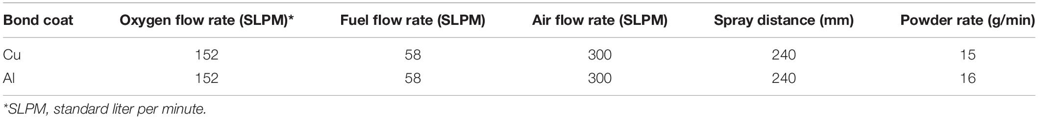
Table 1. HVOF spraying parameters for the metallic bond coats.

Table 2. Plasma spray parameters for NiCrAlY coating and YSZ coating.
Characterization Methods
Thermophysical Properties and Thermal Shock
A high temperature dilatometer (DIL 402C, Netzsch, Germany) was used to record the linear thermal expansion behaviors of samples under atmospheric condition. The sample size for thermal expansion test is 23 × 5 × 3 mm. The thermal diffusivity and the heat capacity of the sample were recorded by laser flash device and PE DSC-2C, respectively. The thermal conductivity of samples can be calculated by the formula as follows:
where α is the thermal diffusivity (mm2/s), CPis the specific heat capacity (J/(g⋅K)) and ρ is the density of sample (g/cm3).
In the thermal shock test, the coating sample is placed in an oven at 230°C for 1 h, and then suddenly quenched into ice water followed by drying and heating. After each cycle, check the sample with a microscope for delamination or cracks. This procedure is repeated until cracks or delamination appear in the sample, and the cycling number was regarded as the thermal shock lifetime of the coating. If more than 10% of the coating surface is peeled off, the coating is judged to be invalid.
Thermal Ablation Test (TAT)
The thermal ablation test of the sample was carried out with a high temperature hot air gun, which was employed to evaluate thermal ablation resistance of the different coating systems under high temperature. The sample size for thermal ablation test is 60 × 30 × 3 mm. The surface temperature is measured by a thermocouple located at the surface center. Measure the temperature difference between the front and back of the sample. During the test, the test temperature of hot gas was 800 ± 10°C, and then it was kept at the peak temperature for 5 min. Then, the hot air gun was removed and the sample was cooled down to room temperature. After the thermal ablation test, the weight loss rate of the sample (w%) was calculated by the following equation:
where m0 and m1 were the mass of the sample before and after thermal ablation test, respectively. Moreover, the corresponding mass ablation rate (R) of the sample was obtained according to the formula:
where t was the test time.
Characterization
X-ray diffraction (Smart Lab, Rigaku, Japan) was carried out to identify phase composition of the coating by using Cu Kα radiation (λ = 0.15406 nm), with a scan rate of 8°/min from 20 to 90°, and it was operated at an accelerating voltage of 40 kV and an emission current of 50 mA. Field emission scanning electron microscope (SEM, XL 30 ESEM FEG, Micro FEI Philips) was used to examine the cross-sectional microstructure of the sample. In this work, for the cross-sectional microstructure analysis, the samples were embedded in the resin and polished down to 1 μm by using the diamond paste. Use Image J software to calculate the porosity of the coating through the image analysis (IA) method, and select at least five pictures with the same magnification for statistical analysis.
Mechanical Properties
The bending and tensile tests were carried out using universal testing machine (CMT5105, MTS). Flexural strength was evaluated by three-point bending test, which according to the standard of GB/T 14452-1993. The sample size for bending test is 80 × 9 × 3 mm.
Coating adhesion test was carried out by uses the pull-off method (Determination of adhesion of coats—Pull-off test, GB/T 5210-85 (eqv ISO 4624) “Determination of adhesion of coatings”) (Nicholls et al., 2002). The bonding strength of the coating was determined by the maximum tensile force that the coating can bear before peeling. The bonding strength was calculated according to:
where P is the maximum load when the sample fails; A is the actual area of the coating bonded to the cylinder. Five pairs of samples are used for each test, and the experimental result is the average of all test results.
Particle Temperature and Speed in HVOF Flame
In order to find out the reason for the difference in bonding strength between the Cu/Al coatings and the substrate, the thermal spray real-time monitoring system Accura Spray G3 was used to monitor the speed and temperature of particles in flight in the HVOF flame. In this system, the speed and surface temperature of individual particles are measured by the time-of-flight method and the two-color high-temperature method, respectively. The size of the powder particles used for spraying is 20–32 μm, the distance between the spray gun outlet and the sensor centerline axis is 190 mm, the nitrogen flow rate is 35 L/min, and the hydrogen flow rate is 12 L/min. The kinetic energy of the particle can be described by the following equation:
where E is the kinetic energy (J), m is the mass of 1 cm3 particles (g), vis the velocity of the particle reaches the substrate (m/s). The densities of Cu, Al and Zn are 8.92, 2.702, and 7.14 g/cm3, respectively.
Particle Penetration Test
In order to further verify the difference between the kinetic energies of Cu and Al particles and the adhesion strength with the substrate, 5 holes with a diameter of 1.0 mm were drilled into the substrate. Substrates were sprayed with different metal powders to observe the penetration of the metal coating into the holes. The spraying parameters are shown in the Table 3. The blockage state of the holes of the sample is analyzed by SEM.

Table 3. HVOF spraying parameters for the metallic bond coats.
Results and Discussion
Phase Composition of the Coating
The XRD pattern of four samples are illustrated in Figure 1. By comparing with the standard card, the XRD characteristic peaks of Al and YSZ are found match perfectly with the standard card Al (JCPDS 65-2869) and YSZ (JCPDS 82-1241), indicating that neither Al nor YSZ was oxidized and no new phase is formed during spraying. However, the weak diffraction peaks of Cu2O (JCPDS 99-0041) are discovered in deposited Cu coating, which indicates that the Cu coating is oxidized during spraying and Cu2O was formed. It is worth noting that there is no chemical reaction between different coatings in the high temperature melting state, indicating that there is a good compatibility between the coatings at the service temperature.
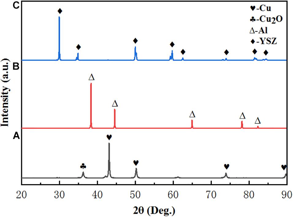
Figure 1. XRD patterns of as-deposited coatings: (A) Cu, (B) Al, and (C) YSZ.
Thermal Conductivity
Thermal conductivity is an important parameter reflecting the thermal insulation ability of the coating, which can be calculated by Equation (1). In the triple-layer coating system, the YSZ ceramic top coat is the main thermal insulation layer, which determines the thermal insulation performance of the coating system. The relevant thermal conductivity parameters of C50N50Y200 coating are shown in Figure 2. It can be seen from Figure 2. that the specific heat capacity of the coating increases gradually from 0 to 1,400°C, and the thermal conductivity of the coating decreases with temperature up to 200°C and then increases with the temperature. The thermal conductivity of the coating is in the range of 1.038–1.288 W/(m⋅K), and the lowest thermal conductivity is 1.038 W/(m⋅K) at 200°C. According to the heat conduction theory, the heat conduction in the low temperature section is mainly through the phonon conduction. As the temperature continues to increase, the phonon scattering increases, the average free path decreases, resulting in a decrease in thermal conductivity. In the high temperature section, the heat conduction is mainly through photon conduction, so the thermal conductivity will increase. Compared with the thermal conductivity of the substrate (7.6–9.1 W/(m⋅K); Abedi et al., 2018b), the low thermal conductivity of the coating system can effectively improve the long-term endurance temperature of the substrate.
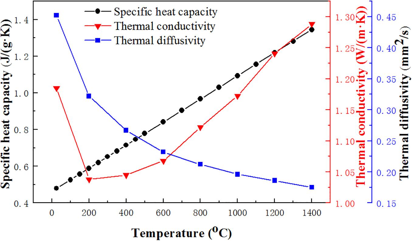
Figure 2. Thermophysical properties of coating C50N50Y200.
Thermal Shock Resistance
The cross-sectional microstructures of the coating systems after deposition are exhibited in Figure 3. It can be seen that there are some pores on the coating, which is due to the aggregation of incompletely melted particles and fully melted particles, and leads to the formation of pores in the contact part of molten droplets. For all these coating systems, there are no apparent pores present in the Al layer and Cu layer, while many pores are distributed irregularly in the YSZ layer. Compared with metallic bond coat, cracks on the top coat can grow, expand and connect to form pores during the deposition process to release stress. The porosity of the coating was calculated using Image J, and the 8YSZ layer was 16.5%, the NiCrAlY layer was 20%, the Cu layer was 11.67%, and the Al layer was 3.64%.
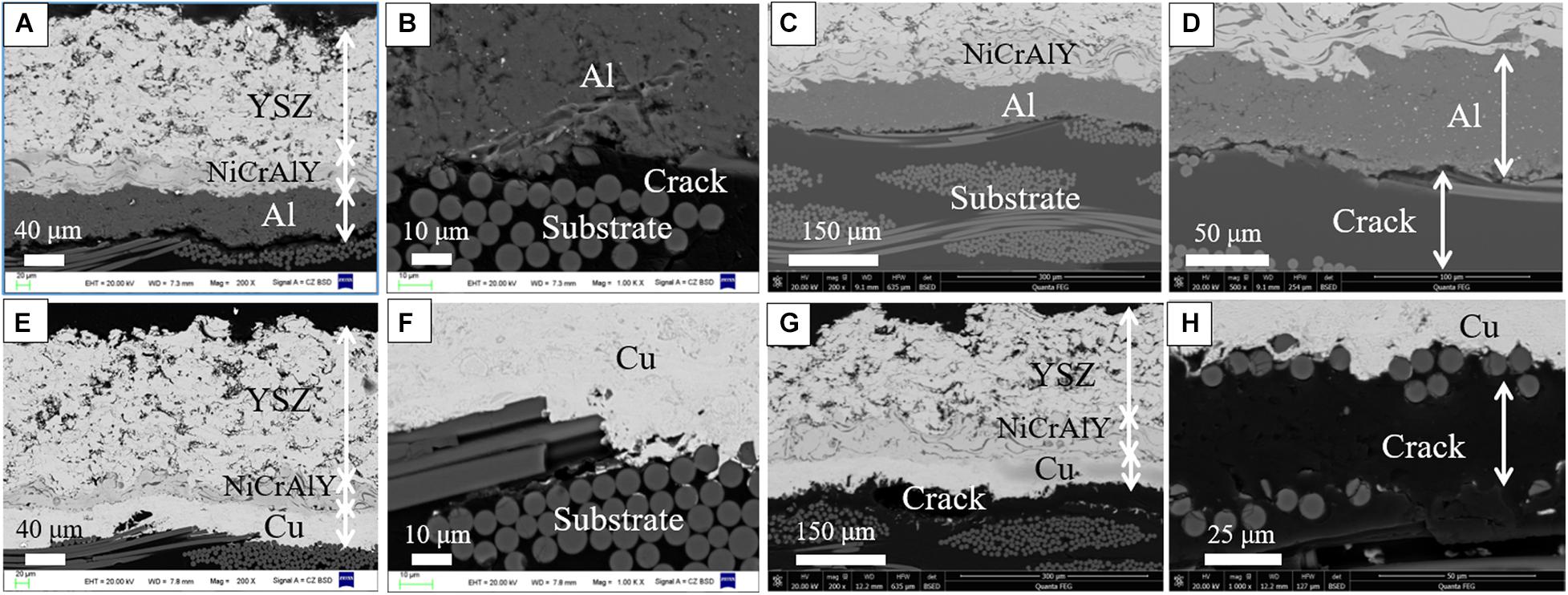
Figure 3. SEM cross-section macrographs of different TBCs after deposition: (A,B) A50N50Y200; (E,F) C50N50Y200; SEM cross-section macrographs of different TBCs after thermal shocking at 230°C: (C,D) A50N50Y200 after 20 thermal shocks, (G,H) C50N50Y200 after 182 thermal shocks.
It can be seen from Figure 3C that in the Cu/NiCrAlY/8YSZ system, the substrate/Cu interface is clean and consistent, without pores or cracks. As can be noted at the Cu/substrate interface, some Cu particles are embedded into the substrate. It is because that the melted Cu particles can penetrate effectively into the substrate, which may be attributed to high kinetic energy and high velocity impact. Due to the high kinetic energy and high-speed impact during the spraying process, the molten or semi-melted particles penetrate the micropores on the outer wall of the substrate, resulting in the formation of a mechanical interlock between the bond coat and the substrate. Figures 3A,B show that at the Al/NiCrAlY interface, there are cracks between the substrate and the Al layer, and the combination is untight. It is speculated that because the density of Al is smaller, the kinetic energy reaching the surface of the substrate is smaller, and the particle spread is lower. In Figures 3E,F, after 20 thermal shocks, the crack of the substrate/Al interface tends to decrease. In fact, there is already a crack, so thermal shock is of little significance. The Figures 3G,H shows that the main failure mode of C50N50Y200 coating is the delamination between the Cu layer and the substrate at the rim part of the sample. When the stress at the Cu/substrate interface accumulated to the maximum bonding strength between the Cu layer and the substrate, leading to the delamination between the Cu layer and the substrate. The stress comes from the mismatch of the thermal expansion coefficient of the coating and the substrate. Delamination mainly occurs at the edge of the sample, which is due to the high stress concentration in edge areas, and it is conducive to the formation and propagation of cracks. It can be seen that the adhesion between the Cu bond coat and the substrate is better than the adhesion between the Al bond coat and the substrate. Consequently, it could be concluded that the coating system composed of Cu as the bond coat exhibited the better thermal shock resistance than Al as bond coat.
Failure mechanism of the coating was mainly ascribable to the formation of cracks, delamination or peeling and the interface thermal stress is the main factor of crack initiation and propagation. If the stress state exceeds the bonding strength of the coating, delamination or peeling may occur (Luzin et al., 2011). Generally, the major stresses in the coating are as follows: (1) the quenching stress caused by the shrinkage of the individual splats during the rapid cooling to the substrate temperature, (2) thermal stress through thermal expansion mismatch during thermal shocking (Kuroda and Clyne, 1991; Stokes and Looney, 2004; Zhang et al., 2005; Wang et al., 2012). Quenching stress is always tensile stress and is caused by the rapid solidification of sprayed droplets, in which contractions are restricted by the underlying layer. However, thermal mismatch stress originates from the difference in thermal expansion between the deposits and the underlying layer. Thermal stress depends on CTE values of the deposit and substrate, which can usually be expressed as (Kuroda and Clyne, 1991; Stokes and Looney, 2004; Zhang et al., 2005):
where δt is thermal stress, αc and αs are the CET value of the coating and the substrate, respectively. Ec is elastic modulus of coating, vc crefers to Poisson’s ratio of coating and Δ T is temperature difference upon cooling. In order to better explain failure mechanism of coating, thermal expansion coefficient (CET) of as-deposited bond coat and substrate is measured and the CET curve is shown in Figure 4. Based on the curve of Figure 4, it is known that at 230°C, the average thermal expansion coefficient of the substrate, Cu, and Al is calculated to be 9.8 × 10⁻⁶, 17 × 10–6, and 25.7 × 10⁻⁶ K–1, respectively. It is worth noting that the CTE of Cu is closer to the substrate as compared with that of the Al when the temperature ranges from 50 to 500°C, and the CTE value of the substrate is lower than the Cu/Al bond coat. According to Equation (6), it can be seen that during the thermal spraying process, the huge difference in CTE value between the two coatings can generate a large thermal stress at their interface, resulting in the sample failure prematurely (Ni et al., 2011). Because the difference in thermal expansion coefficient between Cu and substrate is smaller than that of Al, it can be considered that Cu is more suitable for the bond coat than Al.
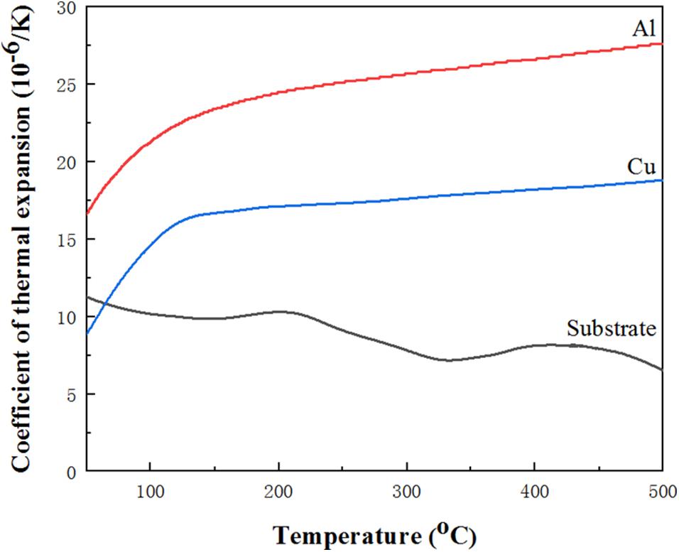
Figure 4. Thermal expansion coefficients of substrate and bond coats.
In order to further study the influence of YSZ coat thickness on thermal shock resistance, Cu/NiCrAlY/8YSZ systems with YSZ coat thicknesses of 100, 300, and 400 μm were also subjected to thermal shock test at 230°C. The cross-sectional micrographs before and after thermal shocking at 230°C of TBCs system with different 8YSZ coat thicknesses are shown in the Figure 5. It can be seen that the common failure mode of all coatings is delamination between bond coat and the substrate, which may be mainly due to the thermal stress caused by the large temperature difference and thermal expansion mismatch (Jamali et al., 2012). The failure mode is similar to the previous coating samples, resulting in pores and cracks at the bond coat/substrate interface. The failure factors of the coating come from the residual stress in deposition processing and the thermal stress during thermal shocking. With the progress of thermal shock test, the interface stress in the coating gradually accumulates, and microcracks will occur in the coating at first. When the stress accumulation exceeds the maximum stress that the coating can bear, the coating will be delaminated (Chen et al., 2010). At the same time, in the later stage of the test, the substrate will be oxidized and cracks will occur at the interface. As the crack gradually spreads, finally resulting in coating spallation.
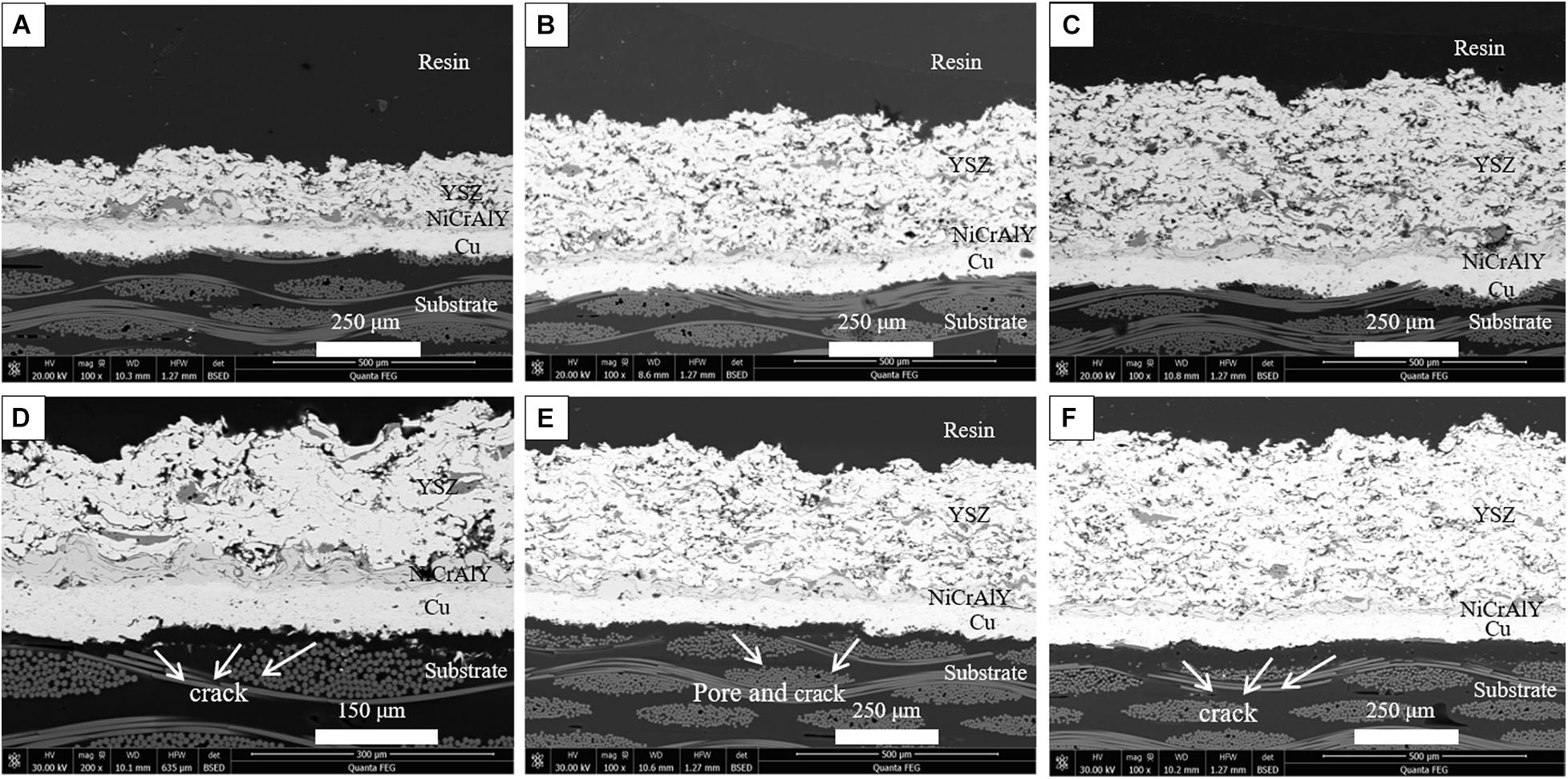
Figure 5. The typical cross-sectional microstructures of coatings with different YSZ coating thickness before and after 230°C thermal shock: (A,D) 100 μm, (B,E) 300 μm, and (C,F) 400 μm.
The thermal shock lifetime of Cu/NiCrAlY/YSZ system with different 8YSZ coat thickness is shown in Figure 6. It can be seen that the TBCs system with 200 μm YSZ thickness has the longest thermal shock lifetime and the best thermal shock resistance. Usually, with the increase of the thickness of the ceramic coating, a certain number of microcracks will occur in the coating, which will help to alleviate the stress concentration of the coating during the thermal shock, further improve the strain tolerance of the coating, and the thermal shock resistance of the corresponding coating will also be enhanced. However, with the increase of thickness, the residual stress will also increase, which will weaken the mechanical adhesion of bond coat/substrate interface, resulting in premature peeling off of the coating (Sun et al., 2018). When the thickness of the YSZ layer increases to 300 μm, the level of residual stress will far exceed the value that the coating system can bear, which will lead to cracks along the coating/substrate interface. The formation of cracks can release the residual stress in the coating and reduce the level of residual stress.
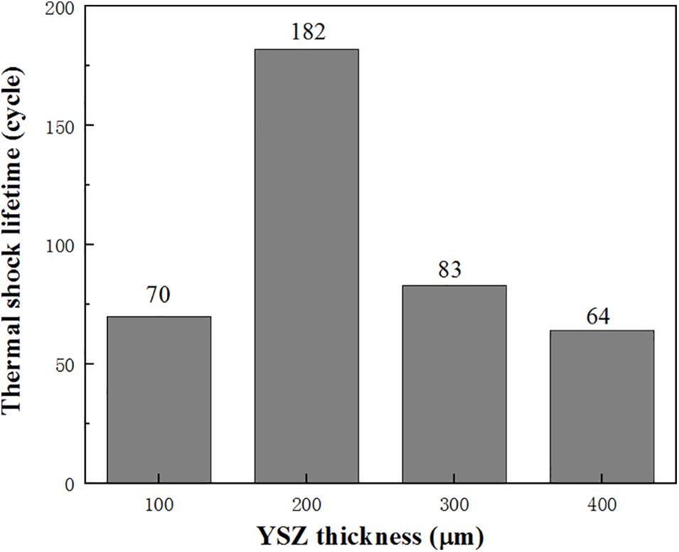
Figure 6. Thermal shock lifetime of TBCs system with different YSZ coating thicknesses at 230°C.
Thermal Ablation Resistance
The thermal ablation resistance of different coating systems was evaluated by thermal ablation test. Figures 7, 8 show the typical cross-sectional microstructure of the coating after the thermal ablation test. The cross-sectional structure of the C50N50Y200 coating at the ablation center region and the ablation rim region after thermal ablation is shown in Figure 7. It can be seen from Figure 7 that in the ablation edge and ablation center Cu layer has a close bond with the substrate, and the coating has good thermal ablation resistance. Delamination occurs in the substrate, and the delamination is serious in the part near the coating. It is noticeable that the resin as the binder of these fibers has been completely decomposed, and the separation between these fibers occurs in the outer layer of the substrate. For the A50N50Y200 coating, it can be seen in Figure 8 that the separation between the Al layer and the substrate mainly occurs in the ablation center region, and the substrate in the ablation center area is obviously delaminated, accompanied by the protuberance of the coating in the central area. In some regions, the bonding between the Al layer and the substrate is still excellent. Compared with the sample before thermal ablation, the coating has vertical cracks and a large number of pores in the vertical direction. The vertical cracks in the coating can provide channels for oxygen to diffuse directly to the surface of the substrate. The porosity of the YSZ coating in the C50N50Y200 coating before and after thermal ablation was 18.24 and 19.58%, and the porosity of the YSZ coating before and after thermal ablation in the A50N50Y200 coating was 17.74 and 23.08%. There are obvious ablation marks on the edges of the pores, it is speculated that the surface cracks of the coating increase at high temperature, oxygen enters the coating through the surface cracks, or the substrate decomposes at high temperature to generate a large amount of gas, which escapes through the cracks between the coatings, resulting in a significant increase in the porosity of the YSZ coat.
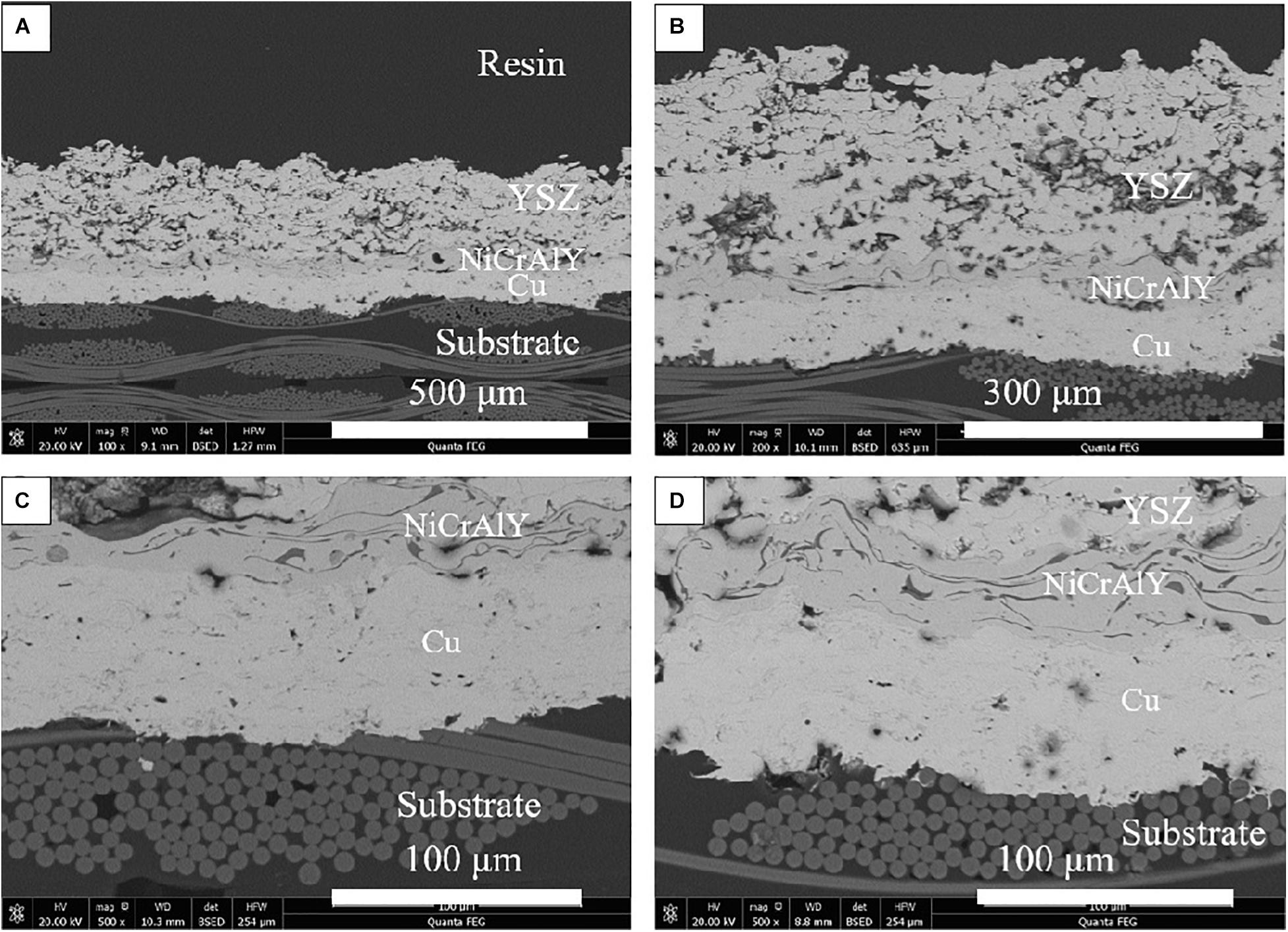
Figure 7. The cross-sectional microstructures of coating C50N50Y200 after thermal ablation test: (A,B) ablation center region and (C,D) ablation rim region.
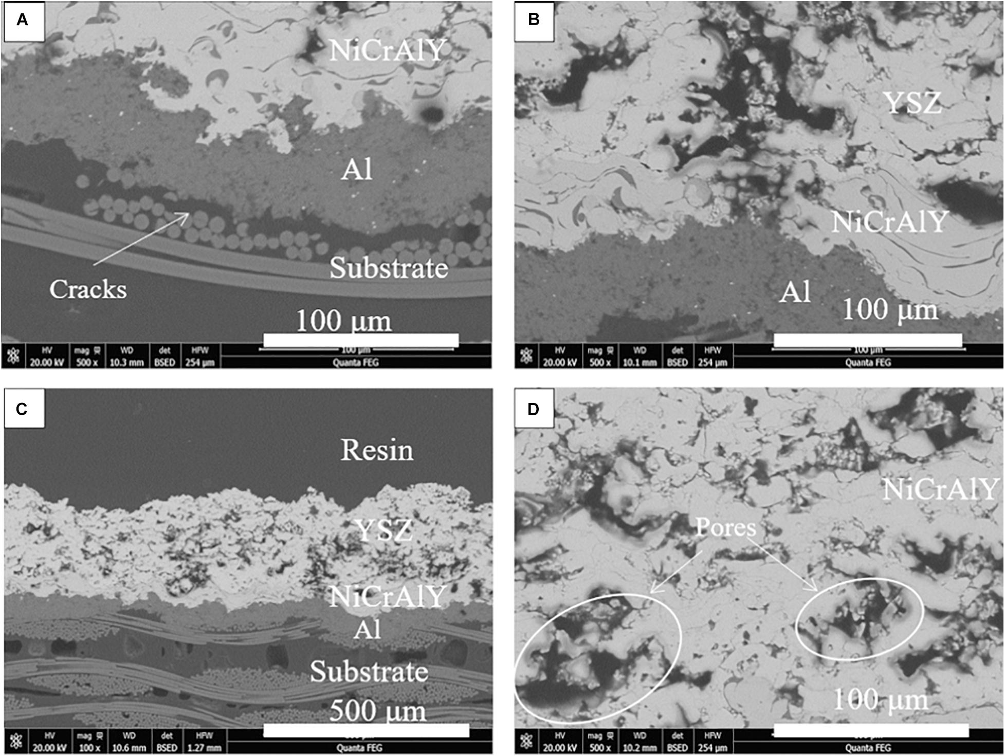
Figure 8. The cross-sectional microstructures of coating A50N50Y200 after thermal ablation test: (A,B) ablation center region and (C,D) ablation rim region.
The XRD pattern in Figure 9 confirms the phase structure of the C50N50Y200 and A50N50Y200 coatings before and after the thermal ablation test. It can be seen from Figure 9 that the surface composition of the C50N50Y200 and A50N50Y200 coatings is 8YSZ. By comparison, it can be found that there is no significant difference in the X-ray diffraction peak positions before and after the test, and no other new phases appear, indicating that no new components are formed in the YSZ coating. Due to strong oxidation, the weight loss rate of the substrate after thermal ablation is 3.65%, and the corresponding mass ablation rate is 0.19 g/s. The weight loss rate of the substrates coated with C50N50Y200 and A50N50Y200 are 1.02 and 1.45%, respectively. The mass ablation rate of the substrate coated with C50N50Y200 and A50N50Y200 are 0.02 and 0.11 g/s, respectively. Compared with the thermal ablation results, it is noticeable that after coated with C50N50Y200 coating, the weight loss rate of the sample decreases greatly from 3.65 to 1.02%, and the corresponding mass ablation rate decreased from 0.19 to 0.02 g/s. In other words, the coating C50N50Y200 can provide a high degree of thermal oxidation and thermal ablation resistance for the substrate under higher temperature.
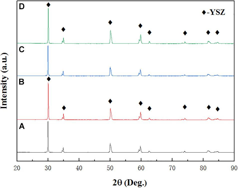
Figure 9. XRD patterns of the different coating systems: coating C50N50Y200 (A) before and (B) after thermal ablation test, coating C50N50Y200 (C) before and (D) after thermal ablation test.
Mechanical Properties of Coatings
The bonding strength between the coating and the substrate determines the quality and reliability of the coating. If the bonding strength between the coating and the substrate is not reliable, no matter how good the other properties are, it will be meaningless. Therefore, high bonding strength is also very important for TBCs. In this study, the “pull-out test” was used to test the bonding properties between the coating and the substrate, and the test results are shown in Figure 10. In general, there are three bonding modes in the process of spraying coating, including mechanical occlusal, metallurgical chemical bonding and physical bonding.
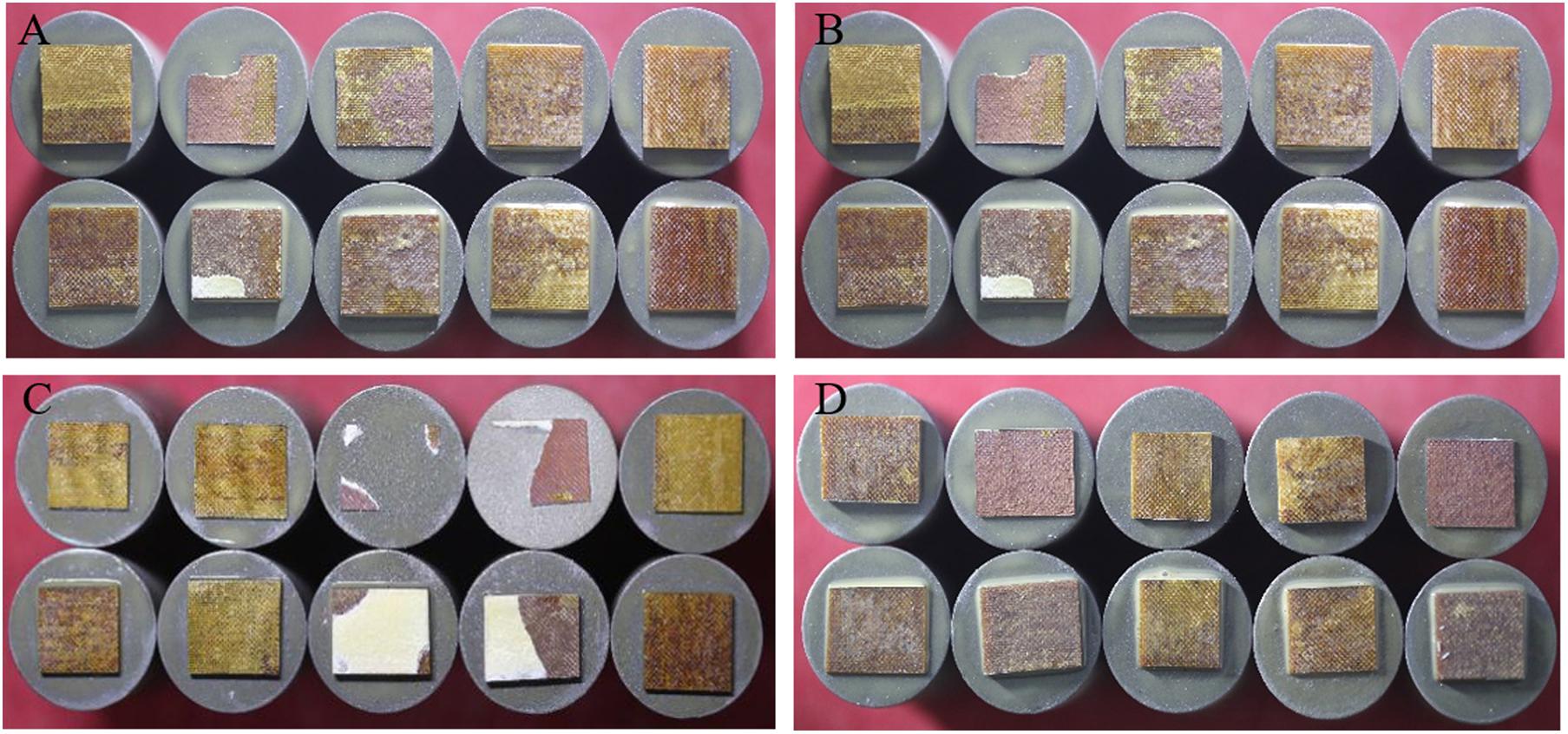
Figure 10. Tensile cross-section macrographs of the tensile failure section of Cu/NiCrAlY/8YSZ coatings with 8YSZ coatings of different thicknesses: (A) 100 μm, (B) 200 μm, (C) 300 μm, and (D) 400 μm.
According to Equation (6), since the CTE value of the YSZ top coat is lower than that of the NiCrAlY intermediate coat, the thermal mismatch stress caused by the YSZ deposition is compressive stress. Therefore, the main reason for the increase of residual tensile stress caused by the increase of coating thickness is the quenching stress caused by rapid solidification of YSZ droplets during deposition. After the tensile adhesion test, the observation of the coating sample shows that the tensile fracture occurs at the interface between the substrate and the Cu layer, or inside the substrate. When the failure occurs at the bond coat/substrate interface, it is confirmed that the bonding strength of the bond coat/substrate is lower than that of the bond coat/intermediate coat. The internal fracture of the substrate indicates that the coating is well bonded, which indicates that the bonding strength of the substrate is insufficient. At this time, the bonding strength between the coating and the substrate is greater than the internal bonding strength of the substrate. When the coating is partially peeled off from the substrate, the bonding strength is close to the calculated value. The bonding strength was calculated by Equation (4). The bonding strength calculated in Figure 10A is 8.29, 3.44, 3.52, 4.57, and 4.93 MPa from left to right, and the bonding strength calculated in Figure 10B is 2.49, 1.97, 10.29, 3.35, 7.04 MPa from left to right. The bonding strength calculated from left to right in Figure 10C is 3.71, 1.88, 5.13, 1.1, 0.68 MPa, and the bonding strength calculated in Figure 10D from left to right is 3.56, 2.34, 4.36, 4.82, 5.25 MPa. The average bonding strength measured is b > d > a > c, that is, when the thickness of YSZ is 200 μm, the bonding strength between substrate and bond coat is the highest.
The bending test was performed to evaluate the ability of the samples to resist external forces. The flexural strength refers to the maximum stress that the material can bear when it breaks or reaches the specified bending moment under the bending load, and the corresponding flexural modulus refers to the ability of the material to resist bending deformation within the elastic limit. It can be observed from Figure 11 that, for the substrate, in the initial stage, the load-deflection curve increases steadily and is almost linear, which is the stage of elastic deformation. When the first load drops suddenly, the outer fiber layer of the substrate breaks, then the internal structure of the sample is re-superimposed, and the corresponding curve increases steadily. When the second load drops suddenly, the internal fiber layer cannot bear the load and break. For the substrate coated with C50N50Y200 and C50N50Y200, before the linear deformation is transformed into plastic deformation, the deformation of the coating and the substrate can still be coordinated with the increase of load. In this process, part of the elastic deformation of the coating is absorbed by the substrate in the process of deformation, meanwhile the load shows the first obvious peak on the curve, and the load drops suddenly after the peak value, and at the same time, longitudinal cracks began to appear in the coating. The latter step-by-step decline is the fracture of the fiber layer inside the substrate. As shown in Figure 12, compared with the substrate, the flexural strength and modulus of the samples decreased slightly after coated with C50N50Y200 and A50N50Y200. After spraying the coating, the brittleness of the sample increases, which is attributed to the inevitable thermal damage in the spraying process. In addition, the ceramic top coat itself is brittle, which will have a slight impact on the mechanical properties of the sample.
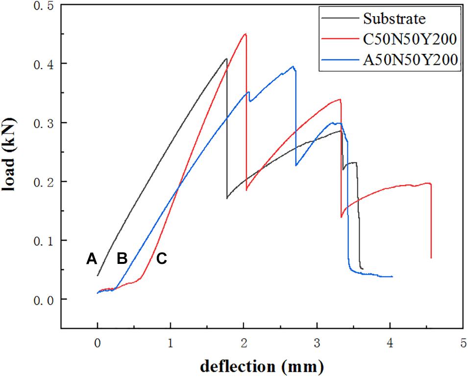
Figure 11. The load-deflection curve of different samples: (A) substrate, (B) substrate coated with A50N50Y200, (C) substrate coated with C50N50Y200.
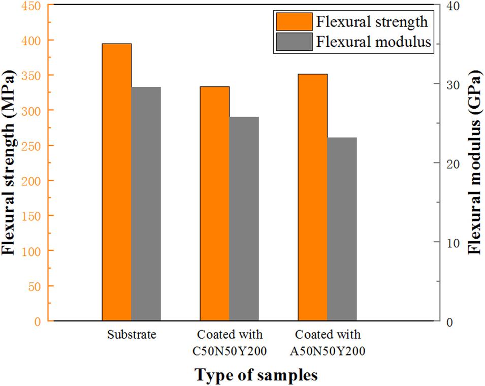
Figure 12. The flexural strength and flexural modulus of different samples.
Particle Kinetic Energy During Spraying
According to the previous tests, it can be seen that the performance of TBCs system with Cu as bond coat is better than that of Al as bond coat. As can be seen in Figure 13, after spraying Cu layer on the substrate, the Cu particles are firmly rooted on the surface of the substrate, like tree roots, closely embedded into the substrate. In Figure 13A, some Cu particles enter the substrate and wrap tightly around the resin fiber to form a strong mechanical interlock. It can be seen more clearly in Figure 13B that some Cu coatings are embedded into the substrate, so the melted Cu particles can penetrate effectively into the out layer of the substrate. It is speculated that the better performance of TBCs system with Cu as boat coat is attributed to its high kinetic energy and high speed impact, which forms a closer mechanical interlock and has better thermal shock resistance and thermal ablation resistance.
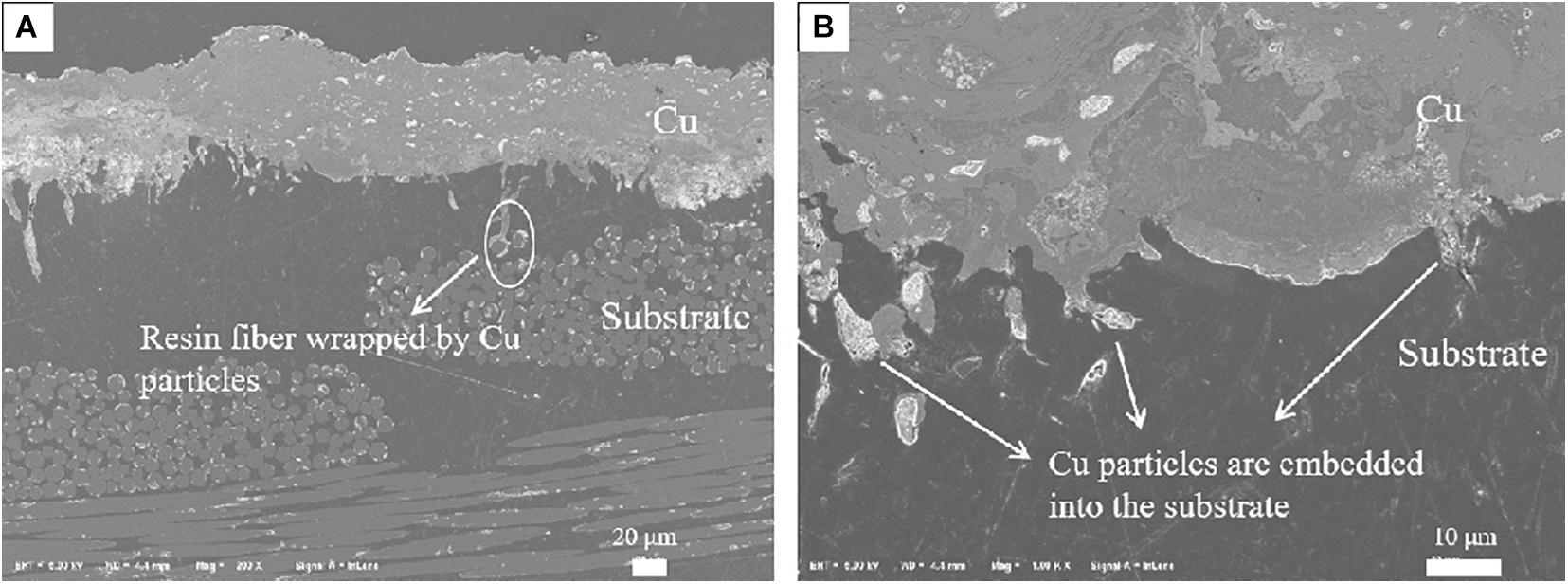
Figure 13. (A,B) The typical SEM cross-section macrographs of the coating systems with Cu as bond coat.
In order to verify the previous conjecture, the velocity and temperature of each 1 cm3 Cu, Al and Zn particles reaching the substrate surface were calculated by using the thermal spraying real-time monitoring system. The fixed spraying distance was 190 mm, each particle test five times, take the average.
It can be seen from Table 4 that the kinetic energy Cu > Zn > Al, the temperature reaching the substrate is also Cu > Zn > Al. When the particles with a certain velocity and temperature collide strongly with the surface of the substrate, part of the kinetic energy of the particles is transferred to the substrate to make the substrate deform, meanwhile the other part remains in the particles to make the particles deform, and the deformation energy is converted into thermal energy to increase the interface temperature. As the sprayed particles continue to hit the surface of the substrate, the deformed particles are gradually deposited on the surface of the substrate. With the continuous stacking of subsequent particles, the particles and particles are interlaced and bonded together, and finally deposited to form a coating (Ivosevic et al., 2006). The greater the kinetic energy of the particles, the stronger the impact on the substrate during the deposition of the particles. And the sufficient change of the shape of the particles is beneficial to the bonding between the particles and the substrates, and between the particles and the particles, so as to improve the bonding strength between the coating and the substrate. At the same time, the higher the particle speed, the shorter the flying time of the particles in the air during the spraying process, the shorter the contact time with the air, and the probability of oxide formation is smaller (Wang et al., 2016). The particles and the substrate are mainly mechanically combined. The softening or melting of the substrate at the interface helps increase the amount of plastic deformation of the substrate and promotes the material to jet, thereby increasing the effective bonding area of the coating and the substrate. In the process of particle flattening, the oxide film at the interface is extruded, and the fresh surface is exposed so that the particles are in close contact with the substrate, resulting in a physical bond that increases the bonding strength between the coating and the substrate. When the particle velocity increases, the excessive particle velocity greatly shortens the residence time of particles in the core area of the plasma jet, resulting in the increasing of porosity. The high porosity of the coating leads to lower thermal conductivity, which is beneficial to the thermal insulation of the coating. Interlaminar pores are considered to be an important factor in reducing the thermal conductivity of the coatings, but high porosity will reduce the bonding strength of the coatings. Therefore, porosity within a reasonable range is essential for obtain a high-performance coating. The density of Cu is higher than Al and Zn, the deposition kinetic energy of Cu particles is higher, the particles spread well on the surface of the substrate, and the bond coat and the rough substrate form mechanical interlocking, so the bonding strength is higher.
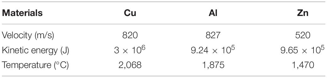
Table 4. The velocity, kinetic energy and temperature of different particles in HVOF flame.
Particle Penetration Test
In order to further verify the influence of kinetic energy, the particle penetration test was carried out. It can be seen from the Figure 14 that the blockage rate of Cu layer is significantly greater than Al layer. As shown in Figures 14A–C, the accumulation of Al layer on the inner wall of the cavity is very little, because the impact force of Al particles is small, and most of the particles cannot enter the cavity. As displayed in Figures 14D–F, there is a large amount of Cu layer accumulated on the inner wall of the hole. In the process of spraying, the molten metal particles continue to accumulate around the hole, some of which flow into the hole and attach to the hole wall, and particles continue to deposit on the attached hole wall. Cu particles have large kinetic energy and large impact force. After the particles hit the substrate at high speed, they will generate high compressive stress at the contact interface, which leads to strong plastic deformation in the local contact area. The strain energy is converted into heat energy. The plastic strain is dissipated in the form of heat, making the interface temperature rises. At the same time, part of the heat of the particles will be transferred to the interface of substrate, which promotes the thermal softening effect of the interface. When the particles collide with the substrate, the plastic deformation is obvious. The particles spread and flatten along the substrate interface, which makes the particles tightly embedded the surface of the substrate and forms a mechanical bond. It is further verified that the deposition kinetic energy of Cu particles is higher than Al particles, the impact force on the surface of the substrate is greater, the combination with the substrate is more sufficient, and form a tighter physical bond under high pressure.
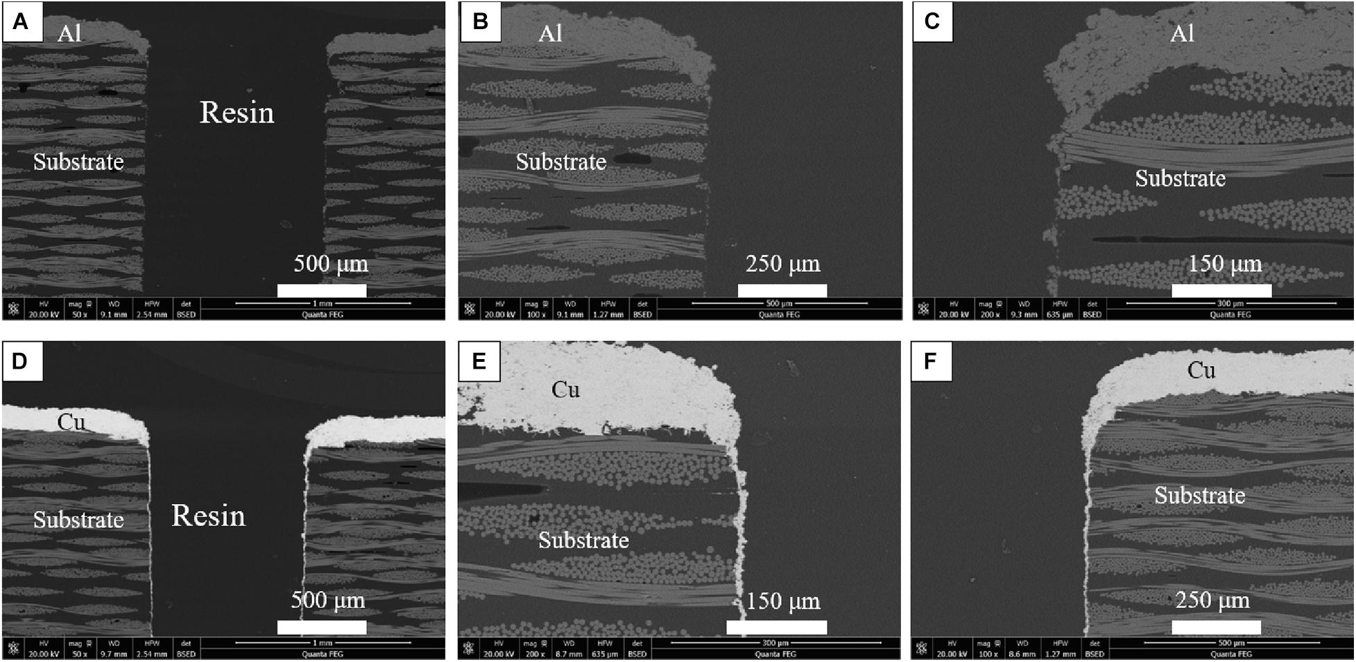
Figure 14. SEM cross-section macrographs around hole after HVOF spraying: (A–C) Al coating and (D–F) Cu coating.
Conclusion
The Cu(Al)/NiCrAlY/YSZ triple layer coating system were deposited on glass fiber reinforced polyimide matrix composites. Some conclusions can be drawn as follows:
(1) The triple-layer coating system has low thermal conductivity and can provide good thermal protection for the substrate. In the thermal shock test, the Cu bond coat is more tightly bonded to the substrate than the Al bond coat, and the thermal shock lifetime is longer.
(2) In the Cu/NiCrAlY/YSZ coating system, when the thickness of the YSZ coating is 200 μm, it has the best bonding strength and the longest thermal cycle lifetime. As the thickness of the YSZ coating increases, the residual stress generated during the deposition process will also increase. When the residual stress accumulates to the maximum that the bond coat/substrate interface can withstand, the bond coat and the substrate are delaminated. After depositing the coating, the flexural strength and modulus of the substrate decreased slightly, which was mainly attributed to the thermal damage on the surface of the substrate during spraying.
(3) The coating system with Cu as the bond coat has better thermal ablation resistance than Al as the bond coat. The weight loss of the sample is reduced from 3.65 to 1.02%, and the corresponding mass ablation rate is reduced from 0.19 to 0.02 g/s.
(4) Under the same spraying conditions, the deposition kinetic energy of Cu particles is larger than Al particles, and the impact force is larger. After high-speed impact on the substrate, there is a great compressive stress at the interface, resulting in plastic deformation of the substrate. The particles are closely embedded in the substrate and form a mechanical interlock, which can explain that the closer bonding between the Cu layer and the substrate after deposition.
Data Availability Statement
The original contributions presented in the study are included in the article/supplementary material, further inquiries can be directed to the corresponding author/s.
Author Contributions
JZ wrote and organized the manuscript. JJ, LD, JH, JY, and XC provided a substantial contribution to the work. All authors approved it for publication.
Funding
This work was financially supported by the National Natural Science Foundation of China (No. 92060201) and the National Science and Technology Major Project (No. 2017-VI-0010-0081).
Conflict of Interest
The authors declare that the research was conducted in the absence of any commercial or financial relationships that could be construed as a potential conflict of interest.
References
Abedi, H. R., Salehi, M., and Shafyei, A. (2017). Mechanical and Thermal Properties of Double-layer and Triple-layer Thermal Barrier Coatings with Different Ceramic Top Coats onto Polyimide Matrix Composite. Ceram. Int. 43, 12770–12780. doi: 10.1016/j.ceramint.2017.06.164
Abedi, H. R., Salehi, M., and Shafyei, A. (2018a). Microstructural, mechanical and thermal shock properties of triple-layer TBCs with different thicknesses of bond coat and ceramic top coat deposited onto polyimide matrix composite. Ceram. Int. 337, 104–116.
Abedi, H. R., Salehi, M., and Shafyei, A. (2018b). Multi-layered thermal barrier coatings on BMI polyimide matrix composite. Surf. Coat. Technol. 337, 104–116. doi: 10.1016/j.surfcoat.2018.01.007
Cao, X. Q., Vassen, R., and Stoever, D. (2004). Ceramic materials for thermal barrier coatings. J. Eur. Ceramic Soc. 24, 1–10. doi: 10.1016/S0955-2219(03)00129-8
Chen, X., Zhang, Y., Zhong, X., Xu, Z., Zhang, J., Cheng, Y., et al. (2010). Thermal cycling behaviors of the plasma sprayed thermal barrier coatings of hexaluminates with magnetoplumbite structure. J. Eur. Ceram. Soc. 30, 1649–1657. doi: 10.1016/j.jeurceramsoc.2010.01.013
Darolia, R. (2013). Thermal barrier coatings technology: critical review, progress update, remaining challenges and prospects. Int. Mater. Rev. 58, 315–348. doi: 10.1179/1743280413Y.0000000019
Duguet, T., Senocq, F., Laffont, L., and Vahlas, C. (2013). Metallization of polymer composites by metalorganic chemical vapor deposition of Cu: surface functionalization driven films characteristics. Surf. Coat. Technol. 230, 254–259. doi: 10.1016/j.surfcoat.2013.06.065
Gonzalez, R., Ashrafizadeh, H., Lopera, A., Mertiny, P., and Mcdonald, A. (2016). A review of thermal spray metallization of polymer-based structures. J. Therm. Spray Technol. 25, 897–919. doi: 10.1007/s11666-016-0415-7
Guanhong, S., Xiaodong, H., Jiuxing, J., and Yue, S. (2011). Parametric study of Al and Al2O3 ceramic coatings deposited by air plasma spray onto polymer substrate. Appl. Surf. Sci. 257, 7864–7870. doi: 10.1016/j.apsusc.2011.04.057
Huang, W., Fan, X., Zhao, Y., Zhou, X., Meng, X., Wang, Y., et al. (2012). Fabrication of thermal barrier coatings onto polyimide matrix composites via air plasma spray process. Surf. Coat. Technol. 207, 421–429. doi: 10.1016/j.surfcoat.2012.07.042
Huang, W., Wang, Z., Xu, J., Fan, X., Wang, Y., Zou, B., et al. (2013). Novel thermal protection coating based on Zr0.75Ce0.25O2/phosphate duplex system for polyimide matrix composites fabricated via a combined sol-gel/sealing treatment process. Corros. Sci. 74, 22–34. doi: 10.1016/j.corsci.2013.04.003
Ivosevic, M., Gupta, V., Knight, R., Cairncross, R. A., Baldoni, J. A., and Twardowski, T. E. (2006). Effect of substrate roughness on splatting behavior of HVOF sprayed polymer particles: modeling and experiments. J. Therm. Spray Technol. 15, 725–730. doi: 10.1361/105996306X146839
Jamali, H., Mozafarinia, R., Razavi, R. S., and Ahmadi-Pidani, R. (2012). Comparison of thermal shock resistances of plasma-sprayed nanostructured and conventional yttria stabilized zirconia thermal barrier coatings. Ceram. Int. 38, 6705–6712. doi: 10.1016/j.ceramint.2012.05.060
Katsoulis, C., Kandola, B. K., Myler, P., and Kandare, E. (2012). Post-fire flexural performance of epoxy-nanocomposite matrix glass fibre composites containing conventional flame retardants. Compo. Part A Appl. Sci. Manuf. 43, 1389–1399. doi: 10.1016/j.compositesa.2012.03.009
Kuroda, S., and Clyne, T. W. (1991). The quenching stress in thermally sprayed coatings. Thin Solid Films 200, 49–66. doi: 10.1016/0040-6090(91)90029-W
Liu, A., Guo, M., Gao, J., and Zhao, M. (2006). Influence of bond coat on shear adhesion strength of erosion and thermal resistant coating for carbon fiber reinforced thermosetting polyimide. Surf. Coat. Technol. 201, 2696– 2700. doi: 10.1016/j.surfcoat.2006.05.012
Lopera-Valle, A., and Mcdonald, A. (2016). Flame-sprayed coatings as de-icing elements for fiber-reinforced polymer composite structures: modeling and experimentation. Int. J. Heat Mass Transf. 97, 56–65. doi: 10.1016/j.ijheatmasstransfer.2016.01.079
Luzin, V., Spencer, K., and Zhang, M.-X. (2011). Residual stress and thermo-mechanical properties of cold spray metal coatings. Acta Mater. 59, 1259–1270. doi: 10.1016/j.actamat.2010.10.058
Mathur, S., and Ruegamer, T. (2011). Transparent and scratch-resistant C:ZrOx coatings on polymer and glass by plasma-enhanced chemical vapor deposition. Int. J. Appl. Ceram. Technol. 8, 1050–1058. doi: 10.1111/j.1744-7402.2010.02537.x
Ni, L. Y., Liu, C., Huang, H., and Zhou, C. G. (2011). Thermal cycling behavior of thermal barrier coatings with HVOF NiCrAlY bond coat. J. Therm. Spray Technol. 20, 1133–1134. doi: 10.1007/s11666-011-9647-8
Nicholls, J. R., Lawson, K. J., Johnstone, A., and Rickerby, D. S. (2002). Methods to reduce the thermal conductivity of EB-PVD TBCs. Surf. Coat. Technol. 151, 383–391. doi: 10.1016/S0257-8972(01)01651-6
Saputo, J. C., Smith, G. M., Lee, H., Sampath, S., Gingrich, E., and Tess, M. (2020). Thermal swing evaluation of thermal barrier coatings for diesel engines. J. Therm. Spray Technol. 29, 1–15. doi: 10.1007/s11666-020-01117-3
Siegel, J., and Kotal, V. (2007). Preparation of thin metal layers on polymers. Acta Polytech. 47, 9–11. doi: 10.14311/904
Stokes, J., and Looney, L. (2004). Residual stress in HVOF thermally sprayed thick deposits. Surf. Coat. Technol. 177, 18–23. doi: 10.1016/j.surfcoat.2003.06.003
Su, Y. J., Wang, H., Porter, W. D., Lopez, A. R. D. A., and Faber, K. T. (2001). Thermal conductivity and phase evolution of plasma-sprayed multilayer coatings. J. Mater. Sci. 36, 3511–3518. doi: 10.1023/A:1017932617123
Sun, C., Min, J., Lin, J., Wan, H., Yang, S., and Wang, S. (2018). The effect of laser ablation treatment on the chemistry, morphology and bonding strength of CFRP joints. Int. J. Adhes. Adhes. 84, 325–334. doi: 10.1016/j.ijadhadh.2018.04.014
Tamaddon Masoule, S., Valefi, Z., Ehsani, N., and Qazi Lavasani, H. (2016). Thermal Insulation and thermal shock behavior of conventional and nanostructured plasma-sprayed TBCs. J. Therm. Spray Technol. 25, 1–8. doi: 10.1007/s11666-016-0476-7
Tant, M. R., Mcmanus, H. L. N., and Rogers, M. E. (1995). High-Temperature Properties And Applications Of Polymeric Materials. Washington, DC: American Chemical Society. doi: 10.1021/bk-1995-0603
Unger, R. H., and Grossklaus, W. D. (1992). A Comparison of the Technical Properties of Arc Sprayed Versus Plasma Sprayed Nickel-5 Aluminum. SAE Transactions 101, 18–23. doi: 10.4271/920931
Voyer, J. L., Schulz, P., and Schreiber, M. (2008). Electrically Conductive Flame Sprayed Aluminum Coatings on Textile Substrates. J. Therm. Spray Technol. 17, 818–823. doi: 10.1007/s11666-008-9228-7
Wang, L., Wang, Y., Sun, X. G., He, J. Q., Pan, Z. Y., and Wang, C. H. (2012). Finite element simulation of residual stress of double-ceramic-layer La2Zr2O7/8YSZ thermal barrier coatings using birth and death element technique. Comput. Mater. Sci. 53, 117–127. doi: 10.1016/j.commatsci.2011.09.028
Wang, L., Wang, Y., Sun, X. G., Pan, Z. Y., He, J. Q., Zhou, Y., et al. (2011). Microstructure and surface residual stress of plasma sprayed nanostructured and conventional ZrO2-8wt%Y2O3 thermal barrier coatings. Surf. Interface Anal. 43, 869–880. doi: 10.1002/sia.3648
Wang, Y., Kang, Y. X., Zhang, L., Tang, J. J., Li, J. R., Chen, H. Y., et al. (2016). Investigation of particle characteristics, composition and microstructure of LaxCe1–xO2–x/2 thermal barrier coatings during supersonic atmospheric plasma spray using Box–Behnken design. Surf. Coat. Technol. 286, 9–15. doi: 10.1016/j.surfcoat.2015.11.046
Zhang, X. C., Xu, B. S., Wang, H. D., and Wu, Y. X. (2005). An analytical model for predicting thermal residual stresses in multilayer coating systems. Thin Solid Films 488, 274–282. doi: 10.1016/j.tsf.2005.04.027
Zhou, Q., Chen, H., and Wang, Y. (2010). Region-selective electroless gold plating on polycarbonate sheets by UV-patterning in combination with silver activating. Electrochim. Acta 55, 2542–2549. doi: 10.1016/j.electacta.2009.12.024
Keywords: HVOF, APS, polymer matrix composite (PMC), thermal shock resistance, bonding strength
Citation: Zhou J, Jiang J, Deng L, Huang J, Yuan J and Cao X (2021) Influence of Bond Coat on Thermal Shock Resistance and Thermal Ablation Resistance for Polymer Matrix Composites. Front. Mater. 8:672617. doi: 10.3389/fmats.2021.672617
Received: 26 February 2021; Accepted: 19 April 2021;
Published: 14 May 2021.
Edited by:
Hao Zhang, Jiangxi Science and Technology Normal University, ChinaReviewed by:
Weihong Lu, Hengyang Normal University, ChinaMehdi Derradji, Polytechnic School of Algiers, Algeria
Copyright © 2021 Zhou, Jiang, Deng, Huang, Yuan and Cao. This is an open-access article distributed under the terms of the Creative Commons Attribution License (CC BY). The use, distribution or reproduction in other forums is permitted, provided the original author(s) and the copyright owner(s) are credited and that the original publication in this journal is cited, in accordance with accepted academic practice. No use, distribution or reproduction is permitted which does not comply with these terms.
*Correspondence: Xueqiang Cao, eGNhb0B3aHV0LmVkdS5jbg==