 Xueqiang Lin
 Xiaokang Luo2
- 1School of Materials Science and Engineering, China University of Petroleum (Huadong), Qingdao, China
- 2Lanzhou LS Petroleum Equipment Engineering Co.Ltd, Qingdao, China
- 3Institute for Advanced Materials and Technology, University of Science and Technology Beijing, Beijing, China
- 4Experiment Center of School of Materials Science and Engineering, Shandong University of Science and Technology, Qingdao, China
The corrosion behavior of N80 steel in Multiple thermal fluid environment containing O2 and CO2 was analyzed by Scanning Electron Microscopy (SEM), Energy-dispersive Spectrometry (EDS) and X-ray Diffraction (XRD) techniques. The results showed that, the corrosion products formed on N80 steel showed double layer structure. The outer layer are loose and porous, providing little protection. The inner layer are mainly FeCO3 crystals, and a small amount of Fe2O3 and FeOOH composition. The formation of Fe oxide on the inner layer of the film destroyed the integrity of the inner layer, resulting in localized corrosion. During the development of pitting, Cl− is enriched only at the tip of the pitting hole, which is the main cause of pitting corrosion and eventually leads to the formation of dendritic localized corrosion. The difference between internal and external potentials, the O2 concentration and the decrease of pH in the pitting holes combined to increase the corrosion process.
Introduction
In recent years, the multi-element thermal fluid injection technology has achieved remarkable results in improving the efficiency and production of heavy oil fields, which is expected to become the main means of heavy oil production in the future (Fang et al., 2018; Sun et al., 2020; Yang et al., 2020). The multi-element thermal fluid is composed of high-temperature and high-pressure steam, CO2 and a small amount of O2 produced by the combustion of industrial diesel, crude oil or natural gas (Jiang et al., 2012; Lu et al., 2019; Hu and Jin, 2020). The CO2/O2 coexistence environment under high temperature and high pressure is more severe than the traditional CO2 environment, and the simultaneous occurrence of hydrogen evolution corrosion and oxygen absorption corrosion can easily lead to short-term corrosion failure of oil well pipes (Lin et al., 2013; Hua et al., 2015; Xia et al., 2020).
In the past, many scholars have studied the corrosion of carbon steel in CO2 environment (Elgaddafi et al., 2015; De Motte et al., 2018; Zhang et al., 2005; Tuochuan and Yin, 2019; De Motte and RémyMingant, 2018). CO2 dissolves in water to form H2CO3, which corrodes carbon steel. The anode reaction process is carried out according to Equation 1, and the cathode reaction process mainly includes Equation 2. Studies have shown that the cathodic reaction process will be affected by the pH value (Zhang et al., 2006; Yang et al., 2019): the cathodic process is dominated by the reduction of H+ in acidic media (pH < 4, Eq. 2), the reduction of H2CO3 and HCO3- in neutral and alkaline media (4 < pH, Equations 3 and 4), and in the case of high overpotential, it is the reduction of H2O (Eq. 5).
When carbon steel corrodes only in CO2 environment, Fe2+ formed after active dissolution enters the solution. Once Fe2+ and CO32- in the solution exceed the solubility product of FeCO3, FeCO3 will be deposited and formed on the surface of the substrate (Eq. 6) (De Motte et al., 2018)
The corrosion resistance of carbon steel in the CO2 corrosion system mainly depends on the protection of the FeCO3 corrosion product film (Gulbrandsen et al., 1998; Zhang et al., 2005; Sun et al., 2009; Du et al., 2019). When the FeCO3 corrosion product film is dense and completely covering the surface of the substrate, the protection of the film is better. The metal will be uniformly corroded at a lower corrosion rate. Conversely, when the FeCO3 product film is loose and porous and the adhesion is poor, the protection of the film is also poor. Corrosive ions can easily penetrate the corrosion film to reach the surface of the metal substrate, and comprehensive corrosion will occur at a higher corrosion rate. Uniformly or locally damaged FeCO3 corrosion product film could cause localized corrosion easily, which is also the main reason for the failure of oil and gas pipes (Zhao et al., 2002; Bai et al., 2020).
Pipe materials will suffer from both CO2 and O2 corrosion in a multi-element thermal fluid environment (Sun et al., 2012; Zhu et al., 2019; Zhu et al., 2009). O2 has strong oxidizing properties, which will cause serious corrosion of downhole tubing strings and other oil production facilities, resulting in a great risk of failure. When O2 enters the CO2 corrosion system, the reactions in Equations 7–12 may occur, and the corrosion process is very complicated (Song et al., 2002; Wang, 2009; Du et al., 2019). This will lead to changes in the composition and structure of the corrosion products on the surface of the carbon steel, thereby affecting the protective performance of the corrosion product film. Sun Jianbo, Sun Chong and other studies (Martin, 2002; Sun et al., 2016) have shown that when there is a trace of O2 (1,000 ppm), Fe2O3 corrosion products will be produced, which will destroy the continuity of the FeCO3 film and reduce its protection. When the O2 content increases to 2000 ppm, slight pitting corrosion will also be induced. In the multi-element thermal fluid corrosion environment, the O2 content will be as high as 0.5 MPa or more. In this case, the structural changes of the corrosion product film and the protective changes brought about by it are issues that urgently need to be clarified.
Therefore, this paper uses a high temperature and high pressure reactor to study the corrosion behavior of N80 steel in the coexisting CO2/O2 multi-element thermal fluid corrosive environment. The characteristics of the corrosion product film are analyzed by SEM, EDS, XRD and electrochemical analysis techniques to clarify the characteristics of the corrosion product film formed on N80 steel and explore the corrosion mechanism of N80 steel under the condition of coexistence of CO2/O2 multi-element thermal fluid.
Materials and Experiment
N80 steel was used in this study. The chemical composition of the steel is listed in Table 1. The microstructure of N80 steel is shown in Figure 1, mainly consisted of ferrite and cementite. The corrosion medium was simulated producing well water made by a chemical agent at least 99.9% chemically pure, and the soluble ion contents were listed as follows: (mg·L−1): K+ 214.50, Na+ 448.81, Ca2+ 17.99, Mg2+ 8.73, CO32–217.15, HCO3− 742.71, SO42–4.79, Cl− 388.24, pH 8.78.

TABLE 1. Chemical composition of the tested N80 steel (w/%).

FIGURE 1. Microstructure of N80 steel.
Exposure experiments were conducted in a high temperature and high pressure autoclave with a 3 L capacity, as shown in Figure 2. The experimental conditions are listed in Table 2. The arc shaped specimens of 1/8 circle for weight loss tests were machined with dimensions of 87 mm in diameter and 11 mm in width, as shown in Figure 3A. Figure 3B shows the photo of the rotating cage. The sample is fixed on the PTFE rotating cage with silica gel. Except for the exposed test surface, the other parts are sealed with silica gel. Specimen surface were ground with SiC papers up to 800grit, cleaned with acetone and deionized water. Specimens were weighed on an electronic balance with a precision of 0.1 mg and measured by vernier caliper to calculate the corrosion area. For each test, 4 samples were placed in the autoclave and 3 of them were used for the calculation of corrosion rate and 1 was for further corrosion product analysis. Prior to each experiment, the solution was deaerated with pure N2 for 24 h. After the samples and solution were placed in the autoclave, CO2, O2, or O2-containing CO2 was introduced into the autoclave that had been adjusted to the required temperature and pressure. The immersion time of all experiments were 120 h. The starting solution pH at different experimental conditions were predicted using the commercially available OLI software package and are provided in Table 2.
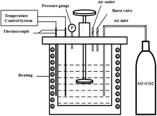
FIGURE 2. Schematic diagram of high temperature and high pressure autoclave.
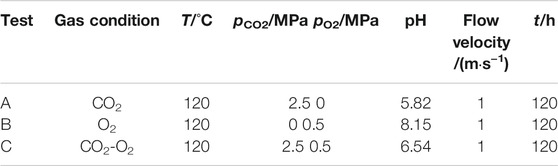
TABLE 2. Experimental parameters of high temperature and high pressure under three gas conditions.
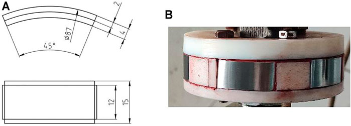
FIGURE 3. (A) sample size of N80 steel for corrosion experiments and (B) rotating cage after samples mounted(unit:mm).
A rotating cage was installed inside the autoclave to imitate the actual flow conditions. The samples were mounted on the rotating cage with silica gel, the length direction was horizontal, the width direction was vertical, and the thickness direction was in the radial direction of cage. The flow velocity can be controlled by adjusting the rotation speed of rotating cage as follows:
where V is the flow velocity (m/s) (1 m/s in this experiment); n is the rotation speed (rps); and R is the radius of rotating cage.
The wall shear stress (τcyl) and Reynolds number (Re) were calculated as follows:
Where ucyl is the electrolyte circumferential velocity (m/s), dcyl is the outer diameter of electrode (m), ρ is the density (kg/m3) and μ is the dynamic viscosity (kg/m/s) of test solution at 120°C.
The Re calculated by Equation 14 is 3.37*105. Taking into account that for a rotating cylinder the critical Reynolds number for the transition from laminar to turbulent flow regime was found to be approximately 200, the flow regime at 1 m/s is turbulent flow, and the τcyl obtained by Equation 15 is 1.737 Pa.
After experiments, DI-water was used to rinse the extracted samples, then dried, and removal of corrosion scales. The corrosion products on the three of the four specimens were removed using a pickling solution with a composition of 500 ml hydrochloric acid, 3.5 g hexamethylenetetramine and 500 ml deionized water at ambient temperature (ASTM G1−03 standard). The scale-removed samples were used to calculate the uniform corrosion rate by the weight loss method. The corrosion rate (CR) was reported in mm/y according to the obtained weight loss via Eq. (16).
where W0 and Wt were the original and final weight of specimens, g, respectively; t was the immersion time, h; ρ was the density of steel, g/cm3; and S was the exposed surface area, cm2.
The chemical composition and the microstructure of the corrosion product scale were characterized by scanning electron microscopy (SEM), energy dispersive X-ray spectrometry (EDS) and X-ray diffraction (XRD).
Result and Discussion
Corrosion Rate
The general corrosion rates of N80 steel under different conditions were shown in Figure 4. The corrosion rates of N80 steel in CO2-only and O2-only environment were 1.5 mm/y and 2.0 mm/y, while the corrosion rate reached 4.5 mm/y in O2-containing CO2 environment, which was significantly greater than that in CO2-only and O2-only environment.
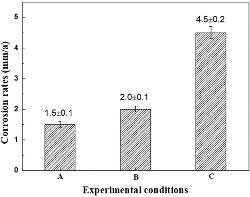
FIGURE 4. Average corrosion rates of N80 at different experiment conditions A: CO2 2.5MPa; B: O2 0.5MPa; C: CO2 2.5MPa, O2 0.5MPa.
The corrosion rates of N80 steel in CO2-only and O2-only environment were added up to be 3.5 mm/y while the corrosion rate reached 4.5 mm/y in O2-containing CO2 environment. It was obvious that the corrosion rate of N80 steel in the O2-containing CO2 environment was not only significantly higher than that in CO2-only and O2-only environment, but also significantly higher than the sum of the two rates. Preliminary analysis suggests that in a corrosive environment where CO2 and O2 coexist, the cathodic process is controlled by both hydrogen evolution corrosion caused by CO2 and oxygen reduction corrosion under acidic conditions caused by O2. And the corrosion rate of carbon steel is closely related to the characteristics of the corrosion product film formed in this environment. Therefore, the characteristics of the corrosion product film formed by N80 steel under three corrosion conditions will be analyzed below.
Macroscopic Morphologies
Figure 5 shows the macroscopic morphologies of N80 steels exposed to the CO2, O2 and O2-containing CO2 environments respectively. It can be seen from Figures 5A, 4B that the corrosion products formed on the surface of N80 steel were uniform coverage with dark brown color. The surface of samples was smooth after the removal of the corrosion products, indicating that the corrosion type was uniform corrosion in CO2-only environment. When the corrosive environment contained only O2, the surface of N80 steel was brown and the corrosion products were very loose and distributed in the direction of the fluid (Figures 5C,D). The adhesion of the corrosion product film to the substrate was weak and easy to fall off. It can be seen from Figures 5E,F that the corrosion products on the surface of N80 steel were yellowish-brown in the corrosive O2-containing CO2 environment, and the coverage was uniform. The yellowish-brown corrosion product was iron oxide formed due to the oxidation of Fe2+ to Fe3+ in the presence of O2, which was weak in adhesion to the inner layer and easily fell off. After the removal of the corrosion products, the surface of the substrate showed a large number of needle-like pores, assuming a typical pinhole-like pitting morphology.
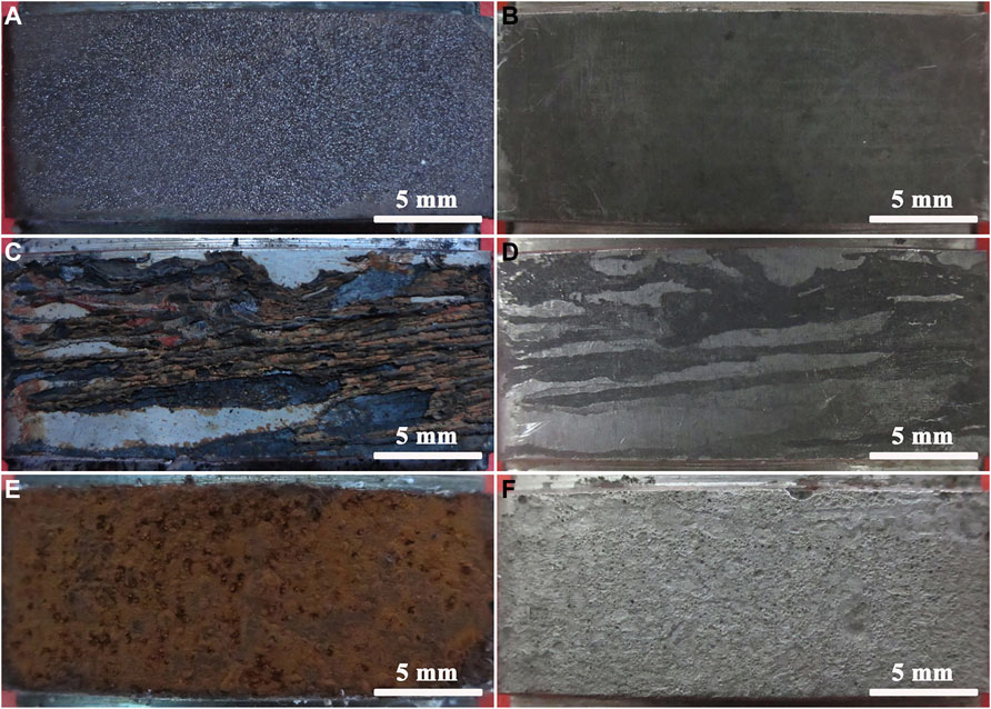
FIGURE 5. Macro morphologies of the corrosion scale and substrate of N80 steel: (A) Corrosion scale, CO2−2.5 MPa; (B) Substrate, CO2−2.5 MPa; (C) Corrosion scale, O2−0.5 MPa; (D) Substrate, O2−0.5 MPa; (E) Corrosion scale, CO2-2.5 MPa, O2−0.5 MPa; (F) Substrate, CO2-2.5 MPa, O2−0.5 MPa.
It can be seen that the corrosion product film of N80 steel was formed with FeCO3 closely stacking on the surface in the atmosphere containing only CO2, and the corrosion product film was uniform and compact, which effectively prevented the corrosive medium from reaching the interface between the film and substrate. Compared with the other two corrosion conditions, the corrosion protection of N80 steel was stronger, so the corrosion rate of N80 steel was lower in CO2-only atmosphere. In contrast, the corrosion product film formed on the surface of N80 steel was extremely loose and had no protective effect for the substrate in O2-only atmosphere. However, due to the low O2 partial pressure under the experimental conditions, the corrosion rate of N80 steel was low. The corrosion products formed on the surface of N80 steel in O2-containing CO2 environment were porous and led to the formation of serious pinhole-like corrosion on the substrate, which was characterized to be serious pitting corrosion. However, due to its concealment, it could cause more damage under actual working conditions.
X-ray Diffraction of the Corrosion Scale
The corrosion products formed by the corrosion of N80 steel in the presence of CO2-only and O2-containing CO2 environment for 120 h were scraped off from the surface of the sample with a blade to form powders. The XRD analysis was shown in Figure 6A which indicated that the main components of corrosion scales were FeCO3 in the CO2-only system. The corrosion products consisted of bulky FeCO3, spherical Fe2O3 and FeOOH in the O2-containing CO2 environment (Figure 6B). The quantitative analysis for the composition of the two corrosion product films showed in Table.3. It can be seen that the presence of O2 caused the oxidation of FeCO3 products to iron oxides on the N80 steel in CO2-only environment, resulting in the coexistence of a variety of corrosion products in the O2-containing CO2 environment.
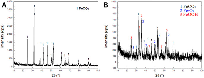
FIGURE 6. XRD patterns of corrosion scale on N80 steel under CO2 and CO2-O2 conditions: (A) CO2−2.5 MPa; (B) CO2−2.5 MPa,O2−0.5 MPa.
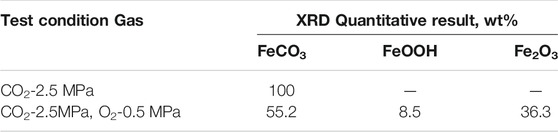
TABLE 3. Results of XRD quantitative calibration.
Morphologies of Outer Layer
Figure 7 shows the surface morphology and EDS analysis of the corrosion products of N80 steel in the presence of CO2 and O2 alone and in the mixture of CO2 and O2 for 120 h. It can be seen that the morphology of the corrosion product film on the surface of N80 steel specimen is significantly different under the three kinds of gas corrosion conditions. Form Figure 7A, it can be concluded that the corrosion products on the surface of N80 steel were formed by compact FeCO3 grains in the atmosphere containing only CO2, which can effectively prevent the corrosive ions from reaching the interface between product film and substrate, thereby providing a good protection for the substrate. It can be seen from Figures 7B,C that in the O2-only environment N80 steel surface was covered by the formation of granular corrosion products, which were porous and easily to be crushed into powder, and therefore, the protective effect on the substrate was weak. The results of EDS spectra of Figure 7D showed that the corrosion products mainly consisted of Fe and O elements, indicating that the corrosion products formed on the surface of N80 steel under O2-only condition were iron oxides. As shown in Figures 7E,F, the morphology of the corrosion products on the surface of N80 steel in the O2-containing CO2 environment was very similar to that in the O2-only environment, consisting of fine granular corrosion products. The EDS results in Figure 7H showed that the granular corrosion products were mainly composed of Fe and O elements. The corrosion product film was loose and porous, and part of the products peeled off. As shown in Figure 7G, the inner layer film was exposed with FeCO3 grain morphology.
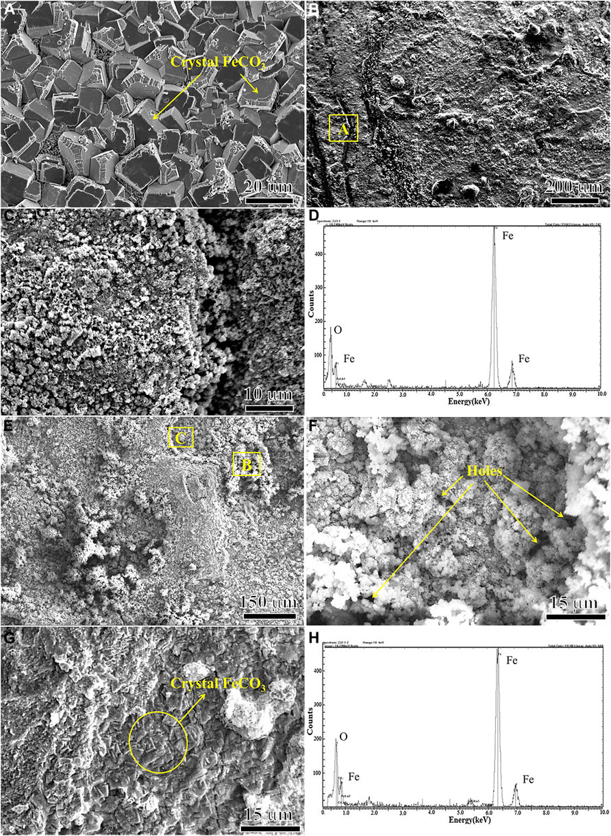
FIGURE 7. SEM micro morphologies and EDS of outer corrosion scale on N80 steel under different experimental conditions: (A) CO2−2.5 MPa; (B) (C) (D) O2−0.5 MPa; (E) (F) (G) (H) CO2−2.5 MPa, O2−0.5 MPa.
Microscopic Morphologies of Inner Layer
Due to the weak adhesion between the outer layer of loose product membrane and the inner membrane, the outer layer was easily to be removed with scotch tape. The inner layer was observed in the O2-containing CO2 environment. Figure 8A and Figure 8B shows the inner layer morphology of N80 steel after 120 h corrosion test in the O2-containing CO2 environment. It can be seen that there were a large number of nodular protrusions on the surface of the inner layer. Most of the convex areas were covered by corrosion products. There were cavities amid the individual protrusions, through which the corroding medium entered the corrosion product film. At the same time, Fe2+ were diffused into the corrosive medium through the micro-channel of the membrane on the loose corrosion product film, leading to the formation of galvanic corrosion and pitting (Ikeda and Ueda, 1994). There was a void in the middle of the pitting, which may be related to the material loss during the corrosion process. The existence of O2 affected not only the density of the inner and outer corrosion products, but also the integrity of the inner membrane, weakening the protective effect of the product film on the substrate. The corrosion rate and local corrosion susceptibility of carbon steel and low alloy steel were mainly determined by the protective properties of the corrosion product film. To achieve good protection, the corrosion product film must adhere to and cover the entire surface of the sample. Once the corrosion product film is damaged and could not be repaired, local corrosion will occur.
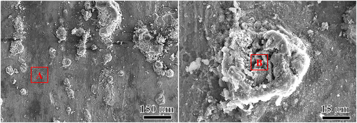
FIGURE 8. SEM micro morphologies of inner corrosion scale on N80 steel under CO2-O2 condition.
Table 4 shows the comparison of element contents between the flat area A and the convex area B after 120 h corrosion test in the O2-containing CO2 environment. The two regions were mainly composed of Fe, O, C and trace amount of Cl, Ca and so on. While the Fe and O contents in the raised region were higher than those in the flat region, there was lower C content in the raised region, although the C content obtained by the EDS test is not accurate. In addition to FeCO3, some iron oxides may be formed on the corrosion product film, resulting in the decrease of FeCO3 content. It is presumed that the formation of pitting may be caused by the formation of an oxide of Fe in inner layer, which destroys the integrity of the inner layer.

TABLE 4. Elemental distribution in inner scale on N80 steel corrosion under CO2-O2 condition (at%).
Cross-Section Morphologies
Figure 9 shows the cross-section morphology of N80 steel after 120 h corrosion test in the CO2 environment and O2-containing CO2 environment. As shown in Figure 9A, N80 steel was tightly covered by single-layer FeCO3 corrosion product and the corrosion product was uniform and complete, with the corrosion product film thickness being about 61 μm. In the O2-containing CO2 environment, the corrosion products on the surface of N80 steel samples showed double-layer film structure, pinhole-like localized corrosion occurred, and the pitting corrosion showed complex dendritic development on the substrate. The average thickness of the corrosion product film without pitting corrosion was about 100 μm (show in Figure 9B), while the greatest pitting depth was about 300 μm (show in Figure 9C). During the experiment, it was found that a large number of pitting pits were filled with corrosive products and well covered by the outer corrosion product film. In the relatively large pitting pits, cavities appeared in the interior of the pitting pits and passed through the corrosion product film (show in Figure 9D).
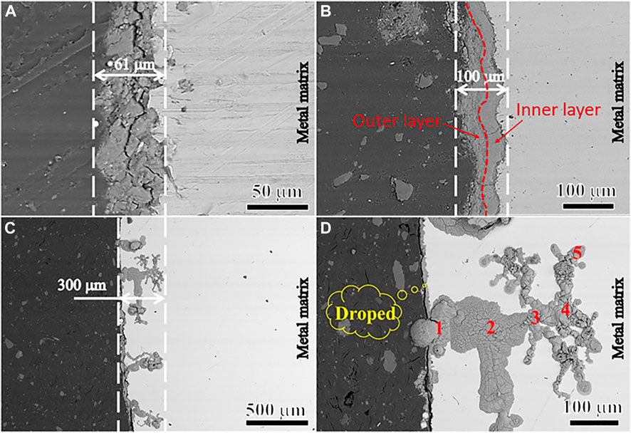
FIGURE 9. Cross-sectional morphology of N80 steel scale-substrate interface under CO2 and CO2-O2 conditions: (A) CO2−2.5 MPa; (B) (C) (D) CO2−2.5 MPa, O2−0.5 MPa.
Figure 10 is an elemental distribution diagram of the corrosion product film at different locations in the pit of Figure 9D. It can be seen that the content of Fe increases significantly with the increase of the depth of pitting, while the content of O element decreases obviously, which indicates that the diffusion of O2 in the solution is suppressed (show in Figure 10A). As can be seen from Table 4, there was Cl− enrichment in the pitting pits, and the Cl− content was lower in the areas without pitting. Ca2+ content was higher in the outer layer of loose membrane and lower at the interface between corrosion product film and substrate. It can be clearly seen from Figure 10B that the Cl− is only enriched at the corrosion product film and the metal interface in the pitting pits to form an enrichment zone.
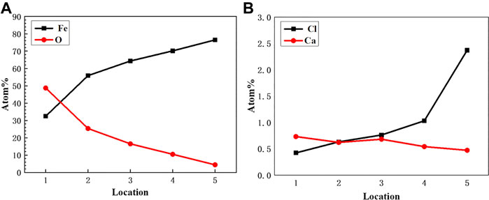
FIGURE 10. EDS element analysis in Pitting.
Discussion
From the above results, it can be seen that the corrosion product film formed by FeCO3 grains after 120 h corrosion on N80 steel in the system containing only CO2 has good protective effect on the substrate, which effectively restrains the corrosive medium from corrosion. The product film contacts with the substrate, and reduces the corrosion rate of the substrate (Zhang et al., 2005; Sun et al., 2009; Gulbrandsen et al., 1998; Du et al., 2019). The formation reaction of the corrosion product film of carbon steel in the system containing only CO2 solution is shown in Eq. 14. With the progress of corrosion, when the Fe2+ and CO32- in the medium was over the solubility product of FeCO3 (KspFeCO3 = 3.2 × 10⁻¹¹), that is, when the FeCO3 super saturation in medium satisfies Eq. 17, FeCO3 deposits on the surface of the sample film. The super saturation of FeCO3 is the main driving force for the formation of FeCO3 product film. The deposition rate is usually slow and high FeCO3 super saturation is a necessary condition for its deposition on the steel surface (Ikeda and Ueda, 1994; De Motte et al., 2018).
The results show that the pitting susceptibility of N80 steel increases sharply when O2 enters into CO2 environment, resulting in more serious pitting behavior compared with the environment with CO2 alone. The corrosion morphology of carbon steel is closely related to the corrosion product film formed on the surface of carbon steel (Martin, 2002; Sun et al., 2016).
When O2 enters the CO2-only environment, the electrochemical reaction of the metal surface will become more complex. From the corrosion current calculation and the measured values, it can be seen that in the cathode, in addition to the occurrence of the hydrogen evolution reaction (Eq. 19), oxygen reaction also occurs under acidic conditions (Martin, 2002; Song et al., 2002; Yu et al., 2013).
O2 is more oxidative than H2CO3 and H+, and the presence of O2 under the same conditions will accelerate the dissolution rate of the anode (Martin, 2002). In addition, sufficient O2 will oxidize Fe2+ to Fe(OH)3 and the precipitation of Fe(OH)3 is more likely to occur on the surface of N80 steel due to its low solubility product ratio (Ksp Fe(OH)3 = 4.0 × 10–38). The reaction shows in Eq.20.
Due to the high solubility product of Fe(OH)2 (KspFe(OH)2 = 8.0 × 10⁻¹⁶), it was found that it was difficult for the precipitation of Fe(OH)2 to occur at pH less than 9.01. Generally Fe2+ reacts with CO32- to form a FeCO3 membrane (Eq. 18).
Corrosion products formed on N80 steel in the O2-containing CO2 environment are porous and corrosive media ions can pass directly through the micro-pores and contact with the inner membrane and the substrate. Fe oxides form on part of the inner layer that damage the integrity of the inner membrane, and cause the occurrence of pitting. Once the pitting is formed, the cathode reaction was oxygen reduction corrosion. Due to the continuous consumption of oxygen in the pitting, the oxygen concentration in the pitting decreased, while the oxygen was still enriched in the solution outside pitting, forming the “oxygen supply difference cell” inside and outside the hole. The anodic dissolution in the pitting increases the concentration of metal ions. In order to keep the electroneutrality, Cl− outside the pits migrates to the hole, causing increase of Cl− concentration in the pits, and the chloride is formed by encountering cation and hydrolysis occurs:
This causes the hydrogen ion concentration in the pit to increase, which decrease pH value and acidification. The Cl− concentration in the pit can be 3–10 times that of the main solution, so that the metal in the pit becomes the anode in the HCl medium, showing an activated dissolved state. The solution outside the pit is still rich in oxygen, where remains near neutral, and the metal outside the pit maintains a passive state to becomes a cathode, where oxygen reduction occurs. This constitutes an activation (in the pit)-passivation (out of the pit) corrosion cell, which develops through a process of autocatalysis [34–37].
The pits are formed on the metal substrate as described above. The surface of the inner layer has a large number of nodular protrusions, and most of the convex regions are well covered by corrosion products. The individual protrusions appear to be hollow, and the corrosive medium passes through these areas into the interior of the corrosion product film, corroding the metal substrate. In the course of pitting corrosion, the metal ions form in the occluded region of iron or carbon steel solution. The occluded region forms in a region where the protrusions are well covered. During the development of pitting corrosion, metal ions are mainly Fe2+ in the solution, but Fe2+ is oxidized to Fe3+ at the outlet of the pitting. As for the pitting holes formed on carbon steel, since the degree of occlusion is lower than the stainless steel, CO32- and other anions will enter the hole. The occlusion cell leads to acidification in the hole and results in a lower pH. This causes the high supersaturation of FeCO3, making it difficult to form protective FeCO3 product film. The distribution of Cl element in the corrosion hole shows that Cl− is enriched only near the interface between the tip film and the substrate in the corrosion hole. It is difficult for O2 to diffuse into the pit due to its slow diffusion rate in the solution, therefore, the concentration of oxygen dissolved inside and outside out of the hole are different, which causes the formation of oxygen concentration cell.
In the O2-containing CO2 environment, the three factors mentioned (corrosive cell, oxygen concentration cell and the reduction of pH) act together to cause the formation of dendritic pitting morphology. Based on the above theory, Figure 11 shows the formation mechanism of the corrosion product film and the development process of the pitting corrosion of N80 steel in the solution containing both CO2 and O2.
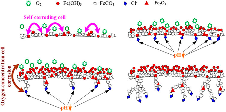
FIGURE 11. Schematic of the formation of film on N80 steel in an aqueous environment containing CO2 and O2.
Conclusion
1) The corrosion products formed in N80 steel under simulated high temperature and high pressure CO2-O2 coexisting aqueous solution showed double membrane structure. The outer corrosion products are loose and porous, with little protection. The inner corrosion products are mainly FeCO3 crystals, and a small amount of Fe2O3 and FeOOH composition.
2) Localized corrosion occurred in N80 steel at high temperature and high-pressure CO2-O2 coexisting aqueous solution. The cause of localized corrosion is the damage of the integrity of the inner film by Fe oxide formed locally in the inner product film. The enrichment of Cl− at the tip of the pits proves that it penetrates the film layer and promotes the local dissolution of the matrix. Acidification caused by dissolution of matrix in the pit results in local dendrites shape like corrosion.
Data Availability Statement
The original contributions presented in the study are included in the article/Supplementary Material, further inquiries can be directed to the corresponding author.
Author Contributions
All authors listed have made a substantial, direct and intellectual contribution to the work, and approved it for publication.
Funding
The authors acknowledge financial support from the National Science foundation of china (grants No.51701240) and the Fundamental Research Funds for the Central Universities (No. 17CX02023A).
Conflict of Interest
XL was employed by Lanzhou LS Petroleum Equipment Engineering Co.Ltd
The remaining authors declare that the research was conducted in the absence of any commercial or financial relationships that could be construed as a potential conflict of interest.
Publisher’s Note
All claims expressed in this article are solely those of the authors and do not necessarily represent those of their affiliated organizations, or those of the publisher, the editors and the reviewers. Any product that may be evaluated in this article, or claim that may be made by its manufacturer, is not guaranteed or endorsed by the publisher.
Supplementary Material
The Supplementary Material for this article can be found online at: https://www.frontiersin.org/articles/10.3389/fmats.2021.721035/full#supplementary-material
References
Bai, H. T., Yang, M., and Dong, X. W. (2020). Research Progress of CO2 Corrosion Product Film[J]. J. Chin. Soc. Corrosion Prot. 40 (04), 295–301. doi:10.11902/1005.4537.2019.150
De Motte, R. A., Barker, R., Burkle, D., Vargas, S. M., and Neville, A. (2018). The Early Stages of FeCO3 Scale Formation Kinetics in CO2 Corrosion. Mater. Chem. Phys. 216, 102–111. doi:10.1016/j.matchemphys.2018.04.077
De Motte, R., and Rémy Mingant, J., (2018). Near Surface pH Measurements in Aqueous CO2 Corrosion[J]. Electrochimica Acta, 290.
Du, M., Zhu, S. D., and Zhang, X. Y. (2019). Research Progress on the Formation and Mechanism of CO2 Corrosion Product Film on Cr-Containing Low-alloy Steel[J]. Corrosion Sci. Prot. Tech. 31 (03), 335–342.
Elgaddafi, R., Naidu, A., Ahmed, R., Shah, S., Hassani, S., Osisanya, S. O., et al. (2015). Modeling and Experimental Study of CO2 Corrosion on Carbon Steel at Elevated Pressure and Temperature. J. Nat. Gas Sci. Eng. 27, 1620–1629. doi:10.1016/j.jngse.2015.10.034
Fang, G. Y., Ma, Z. H., and Gu, Q. L. (2018). Application of Multi-Element thermal Fluid Technology in the Testing of Extra-heavy Oil Exploration Wells[J]. Petrochemical Industry Appl. 37 (05), 11–24. doi:10.3969/j.issn.1673-5285.2018.05.003
Gulbrandsen, E., Nesic, S., and Stangeland, A. (1998). Effect of Precorrosion on the Performance of Inhibitors for CO2 Corrosion of Carbon steel[C]//Corrosion 1998. California: NACE International.
Hu, Y. W., and Jin, D. (2020). Study on Reservoir Parameter Limits of Multiple thermal Fluid Huff and Puff Reservoirs in Heavy Oil Reservoirs[J]. Sci. Tech. Eng. 20 (21), 8537–8542. doi:10.3969/j.issn.1671-1815.2020.21.016
Hua, Y., Barker, R., and Neville, A. (2015). The Effect of O2 Content on the Corrosion Behaviour of X65 and 5Cr in Water-Containing Supercritical CO2 Environments. Appl. Surf. Sci. 356 (NOV.30), 499–511. doi:10.1016/j.apsusc.2015.08.116
Ikeda, A., and Ueda, M. (1994). CO2 Corrosion Behaviour of Cr-Containing steels[J]. Fukuoka: European Federation of Corrosion Publications, 59–93.
Jiang, J., Li, J. S., and Qi, C. X. (2012). Research on the Huff and Puff Technology of Offshore Heavy Oil with Multiple Thermal Fluids[J]. Oil Gas Reservoir Eval. Develop. 2 (04), 38–40. doi:10.3969/j.issn.2095-1426.2012.04.009
Lin, X. Q., Liu, W., and Zhang, J. (2013). Corrosion Behavior of TP100 Steel in High Temperature and High Pressure CO2-O2 Coexistence Environment[J]. Corrosion Prot. 34 (8), 698–701.
Lu, Z., Li, H., and Ding, N. (2019). Research and Application of Multi-Element thermal Fluid Huff and Puff Technology for Middle-Deep Extra-heavy Oil in Xiaowa Oilfield[J]. Spec. Oil Gas Reservoirs 26 (03), 109–113.
Martin, R. L. (2002). Corrosion Consequences of Oxygen Entry into Oilfield Brines[C]. Denver, Colorado: NACE, 2270.
Song, F. M., Kirk, D. W., and Graydon, J. W. (2002). CO2 Corrosion of Bare Steel under an Aqueous Boundary Layer with Oxygen[J]. J. Electrochem. Soc. 149 (11), 479. doi:10.1149/1.1509068
Sun, J. B., Liu, W., and Chang, W. (2009). Characteristics and Formation Mechanism of CO2 Corrosion Product Film of Low Chromium X65 Pipeline Steel[J]. Acta Metallurgica Sinica 45 (01), 84–90. doi:10.3321/j.issn:0412-1961.2009.01.014
Sun, J., Sun, C., Zhang, G., Li, X., Zhao, W., Jiang, T., et al. (2016). Effect of O2 and H2S Impurities on the Corrosion Behavior of X65 Steel in Water-Saturated Supercritical CO2 System. Corrosion Sci. 107, 31–40. doi:10.1016/j.corsci.2016.02.017
Sun, Y. T., Fu, C. Y., and Yang, X. L. (2012). Analysis of Pipe Corrosion in High Temperature Multi-Element thermal Fluid Injection and Production[J]. Chem. Eng. Oil Gas 41 (4), 408–410. doi:10.3969/j.issn.1007-3426.2012.04.013
Sun, Y. T., Li, Z. M., and Wang, Z. Z. (2020). Optimization of Multi-Element thermal Fluid Development Process Parameters for Heavy Oil Reservoirs in Bohai Sea[J]. Sci. Tech. Eng. 20 (25), 10255–10261. doi:10.3969/j.issn.1671-1815.2020.25.019
Tuochuan, Y. Z., and Yin, Z. (2019). Corrosion Electrochemical Behavior of 20 Steel and 16Mn Steel in Simulated CO2 Flooding Environment[J]. Sci. Tech. Eng. 19 (02), 63–68.
Xia, L., Li, Y., and Ma, L. L. (2020). Influence of O2 on the Erosion-Corrosion Performance of 3Cr Steels in CO2 Containing Environment[J]. Materials 13 (3). doi:10.3390/ma13030791
Yang, G. L., Li, Y. H., and He, H. Z. (2020). Research and Application of Multi-Element thermal Fluid Huff and Puff Technology in Super Heavy Oil Reservoirs[J]. Spec. Oil Gas Reservoirs 27 (02), 103–107. doi:10.3969/jissn1006-6535202002016
Yang, Z. C., Cai, Y. Y., and Zhu, Y. S., (2019). Influence of Medium Conditions on CO2 Corrosion of X65 Pipeline Steel and its Welded Joints[J]. J. Corrosion Prot. 40 (10), 717–722.
Yu, B., Li, D. Y., and Grondin, A. (2013). Effects of the Dissolved Oxygen and Slurry Velocity on Erosion–Corrosion of Carbon Steel in Aqueous Slurries with Carbon Dioxide and Silica Sand[J]. Wear 302 (1–2), 1609–1614. doi:10.1016/j.wear.2013.01.044
Zhang, G. A., Lu, M. X., and Wu, Y. S. (2005). Microscopic Morphology and Structural Characteristics of CO2 Corrosion Product Films[J]. Chin. J. Mater. Res. 19 (5), 537–548.
Zhang, G., Lu, M., Chai, C., and Wu, Y. (2006). Effect of HCO3− Concentration on CO2 Corrosion in Oil and Gas fields. J. Univ. Sci. Tech. Beijing Mineral, Metall. Mater. 13 (1), 44–49. doi:10.1016/s1005-8850(06)60012-1
Zhao, G. X., Chen, C. F., and Lu, M. X. (2002). CO2 Corrosion Product Film and Formation of Material Exchange Channels in the Film[J]. J. Chin. Soc. Corrosion Prot. (06), 44–47. doi:10.3969/j.issn.1005-4537.2002.06.010
Zhu, C. M., Liu, G. Z., and Dong, S. X. (2019). The Effect of Temperature on the Corrosion of 3Cr Steel in CO2-O2 Environment[J]. J. Iron Steel Res. 31 (06), 573–581. doi:10.13228/j.boyuan.issn1001-0963.20180267
Keywords: N80 steel, O2 corrosion, CO2 corrosion, corrosion morphology, characteristics of product film
Citation: Lin X, Luo X, Liu W, Chen Y, Pang B, Guo Y and He Q (2021) The Corrosion Behavior of N80 Steel in Multiple Thermal Fluid Environment Containing O2 and CO2. Front. Mater. 8:721035. doi: 10.3389/fmats.2021.721035
Received: 05 June 2021; Accepted: 09 September 2021;
Published: 19 October 2021.
Edited by:
VS Raja, Indian Institute of Technology Bombay, IndiaReviewed by:
Indra Bhushan Singh, Council of Scientific and Industrial Research (CSIR), IndiaIdalina Vieira Aoki, University of São Paulo, Brazil
Copyright © 2021 Lin, Luo, Liu, Chen, Pang, Guo and He. This is an open-access article distributed under the terms of the Creative Commons Attribution License (CC BY). The use, distribution or reproduction in other forums is permitted, provided the original author(s) and the copyright owner(s) are credited and that the original publication in this journal is cited, in accordance with accepted academic practice. No use, distribution or reproduction is permitted which does not comply with these terms.
*Correspondence: Xueqiang Lin, bGlueHVlcWlhbmdAdXBjLmVkdS5jbg== Qingkun He, cWluZ2t1bmhlQDE2My5jb20=