Abstract
Polarization conversion metasurfaces are widely used in optical devices, microwave devices and communication systems, owing to their unique polarization modulation characteristics. However, in some applications (such as folded reflectarrays), the unit cell must be capable of polarization conversion and phase modulation. To the best of our knowledge, there are only a few related designs with both the functionalities. In this paper, we propose a well-performing 1-bit reconfigurable coding metasurface with polarization conversion. It realizes linear-to-linear polarization conversion in a 1.32 GHz bandwidth, and the conversion loss is within 1 dB. Simultaneously, the metasurface achieves a phase difference of approximately 180° by switching the working state of the PIN diodes. This metasurface has great potential for radar detection, folded reflectarrays, and other fields.
1 Introduction
Polarization is one of the most important characteristics of electromagnetic (EM) waves, and is used to describe the change in the electric field vector with time. Polarization provides additional information channels in radio and optical systems for radar tracking, optical fiber communication, and multiple-input and multiple-output (MIMO) communication. Conventional devices for manipulating polarization are usually implemented through the Faraday effect or anisotropic crystals, which are accompanied by problems such as a low conversion efficiency and large volume (Davis et al., 1998; Masson and Gallot, 2006; Xu et al., 2011). Therefore, their integration with other miniaturized devices is inconvenient. As an important way to implement polarizers, metasurfaces show many advantages, such as low profile, low cost and easy integration.
Metasurface is a two-dimensional artificial EM material composed of a subwavelength structure that can flexibly control EM waves and create peculiar physical phenomena. At present, polarization conversion metasurfaces (PCMs) can realize linear-to-linear, linear-to-circular, and circular-to-circular polarization (Gao et al., 2015; Baena et al., 2017; Fernández et al., 2017; Lei and Yang, 2017; Lin et al., 2018; Zheng et al., 2018; Del Mastro et al., 2020; Khan et al., 2020; Lin et al., 2020; Zou et al., 2020; Liu et al., 2021; Shah et al., 2021). Many studies have contributed to PCMs with the advantages of ultrawide bands (Gao et al., 2015; Lin et al., 2018; Khan et al., 2020; Lin et al., 2020; Zou et al., 2020), miniaturization (Lei and Yang, 2017), and conformality (Liu et al., 2021). In addition, some PCMs can convert several bands of EM waves into different polarizations, and some can achieve polarization conversion for both the transmission and reflection of EM waves (Baena et al., 2017; Zheng et al., 2018; Del Mastro et al., 2020; Shah et al., 2021). The properties of the above PCMs are fixed. To overcome this drawback, reconfigurable PCMs loaded with switchable components [PIN diodes, varactors, and microelectromechanical systems (MEMS)] have been proposed to dynamically control the polarization states (Li et al., 2016; Tao et al., 2017; Sun et al., 2018; Ke et al., 2021).
In some situations, it is difficult to satisfy the application requirements by simply changing the polarization of EM waves. For example, phase modulation is required in reflectarrays and transmitarrays in addition to polarization manipulation (Encinar, 2001; Dussopt et al., 2017; Han et al., 2017; Wu et al., 2017). The advantages of reflectarrays and transmitarrays are obvious, but their large focal lengths still limit their practical applications. To solve the problem, the folded reflectarrays/transmitarrays has been further developed. The elements of folded arrays are designed to realize polarization conversion and phase modulation simultaneously, which can reduce the volume of traditional antenna without sacrificing performance. Furthermore, the advent of folded reflectarrays places greater demands on metasurfaces, that is, not only polarization conversion but also phase regulation. Huang et al. (Huang et al., 2016) design a transmitarray with linear- to- circular and circular- to- circular polarization conversion and phase tuning, but the bandwidth remains a significant issue. In our previous study, we proposed a transmitarray with linear polarization conversion and a phase response in a broad band (Gao et al., 2021). However, the transmitarray cannot be applied to the folded reflectarrays. Furthermore, the working principles of transmitarray and reflectarray are different. To achieve simultaneous phase and polarization control, Wang and Dong (2020) designed a reflectarray with linear polarization conversion and compensation phases. Nevertheless, the measured 1 dB reflection bandwidth is close to 2%, which greatly hinders its application in antenna designs.
In this paper, a type of 1-bit reconfigurable coding reflective meta-atom with polarization conversion is proposed, where 1-bit refers to two discrete reflection phase states of 0° and 180°. It achieves a reflection amplitude above −1 dB and a phase difference of 180° ± 5°in two states within a 1.32 GHz bandwidth. Four PIN diodes with opposite working states are applied to achieve polarization conversion and a 1-bit phase response. Moreover, the matching layer technology is adopted to expand the bandwidth. The remainder of this paper is organized as follows. In Section 2, the design and mechanism analysis of the unit are introduced. Section 3 describes the measurement results of the processed sample to verify its performance. Finally, the conclusion is drawn in Section 4.
2 Design and Analysis of the Metasurface
2.1 Design and Simulation of the Unit Cell
The proposed 1-bit coding metasurface with polarization conversion is illustrated in Figure 1. It consists of four metal layers: the first metallic layer, second metallic layer, ground layer and feed layer. The first layer is a multi-split metal ring (Figure 1B) printed on F4B with a thickness of 1.2 mm. There is an air layer with a thickness of 0.1 mm between the second metal layer and the top dielectric substrate. The second metallic and feed layers are etched on two identical F4B substrates separated by the ground layer. Substrates of different thicknesses are bonded together using Rogers 4450F . The total thickness of the unit is 3 mm (0.1λ0, where λ0 is the wavelength of the free space at 10.5 GHz).
FIGURE 1
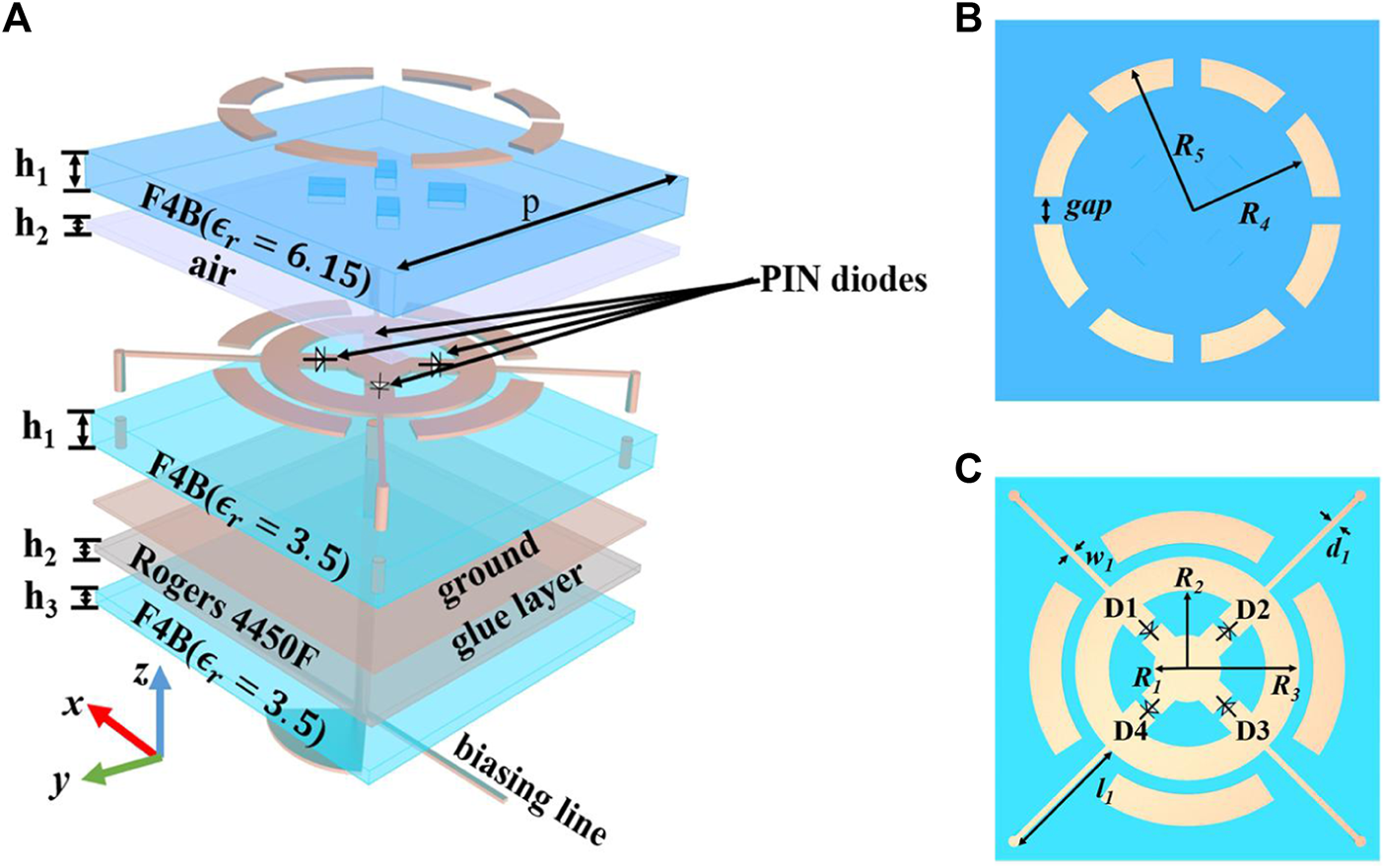
(A) Geometry of the proposed element. (B) First metallic layer. (C) Middle metallic layer.
Four PIN diodes (SMP1321-040LF) are placed in the gaps of the second metallic layer. They are marked as D1, D2, D3, and D4 sequentially, as illustrated in Figure 1C. The working states of D1 and D3 are opposite to those of D2 and D4. The second metallic layer is connected to the bottom structure, composed of a radial stub and a microstrip line, through a central metal column to provide bias. Four diagonal metal columns are connected to the ground plane to achieve zero potential. Because the bias circuit is below the ground plane, the DC and AC can be effectively isolated. The main parameters are finally determined to be as follows: p= 12.8 mm, R1= 1.2 mm, R2= 2.8 mm, R3= 4 mm, R4= 5.5 mm, R5= 4.5 mm, gap = 1 mm, h1= 1.2 mm, h2= 1.2 mm, h3= 0.5 mm, w1= 0.2 mm, l1= 4.57 mm, and d1= 0.2 mm.
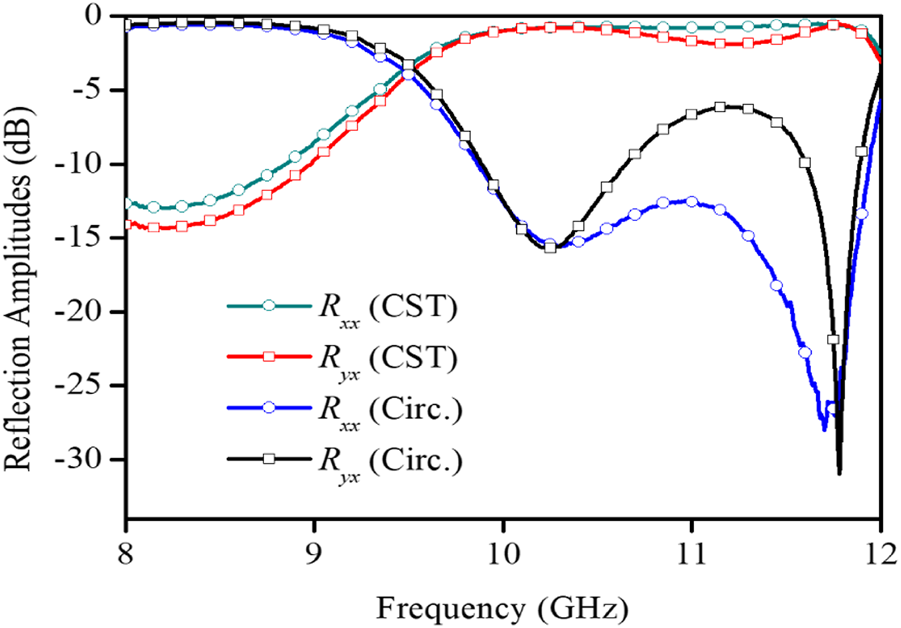
The commercial simulation software CST Microwave Studio is used for numerical simulations. In addition, the Floquet ports are set in the z-direction, and unit-cell boundary conditions are applied in the x- and y- directions. The EM/circuit co-simulation method is adopted, and the measured S-parameters of the PIN diodes are employed to characterize the parasitic characteristics. When the incident EM wave is x-polarized, we define and as the copolarized and cross-polarized reflection coefficients, respectively. The former subscript indicates the polarization direction of the reflected waves and the latter subscript represents the polarization direction of the incident waves. When x-pol waves EM waves are normally incident on the metasurface, the co-polarized and cross-polarized reflection magnitudes of the unit cell and are as shown in Figure 2. At normal incidence, the reflection coefficients and are shown in Figure 2. The lines with hollow and solid circles represent the reflected amplitude of cross-polarisation and co-polarisation respectively, and the line with hollow diamonds represents the phase difference. When D1 and D3 are turned on while D2 and D4 are turned off, the simulation results reveal that the cross-polarized reflection amplitude above −1 dB covers a wide bandwidth of 9.98–11.9 GHz, and the co-polarized reflection amplitude is below −10 dB in the frequency band of 9.87–11.94 GHz. When D1 and D3 are turned off while D2 and D4 are turned on, the simulation results are basically identical to those in the previous state. The results for the x- and y-polarized waves are the same.
FIGURE 2
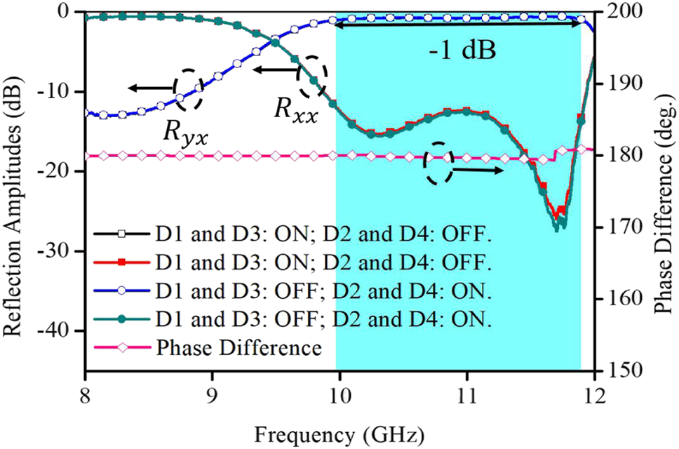
Simulation results for the proposed metasurface at normal incidence.
Notably, this unit cell achieves a broadband phase difference of approximately 180° between the two working cases discussed above, as shown in Figure 2. This shows that the unit proposed in this paper has 1-bit coding ability based on excellent polarization conversion.
2.2 Matching Layer Mechanism to Expand the Bandwidth
The bandwidth of this unit cell is extremely narrow without the matching layer, as shown in Figure 3. Thus, we use the matching layer technique to extend the polarization conversion bandwidth and improve reflectivity. At present, matching layer technology is widely applied to phased array antennas to improve their wide-angle scanning ability and expand bandwidth (Cameron and Eleftheriades, 2015; Yetisir et al., 2016; Cheng et al., 2017).
FIGURE 3
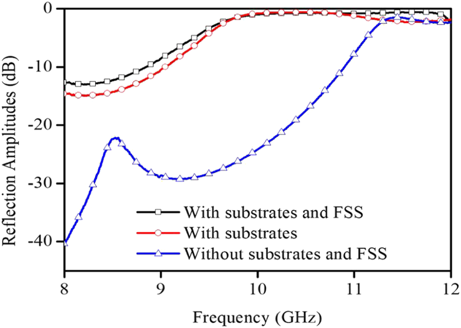
Reflection amplitudes with or without substrates and an FSS.
From the perspective of the equivalent circuit, the dielectric substrate can be regarded as a transmission line with a characteristic impedance of , where is the characteristic impedance of the free space. The thickness of the substrate is equivalent to the length of the transmission line. The port impedance of the middle metallic layer is assumed to be , and we only consider the case of loading the dielectric wide-angle impedance-matching layer. The equivalent circuit is illustrated in Figure 4A. The input impedance obtained from the air layer is , which can be expressed as
FIGURE 4
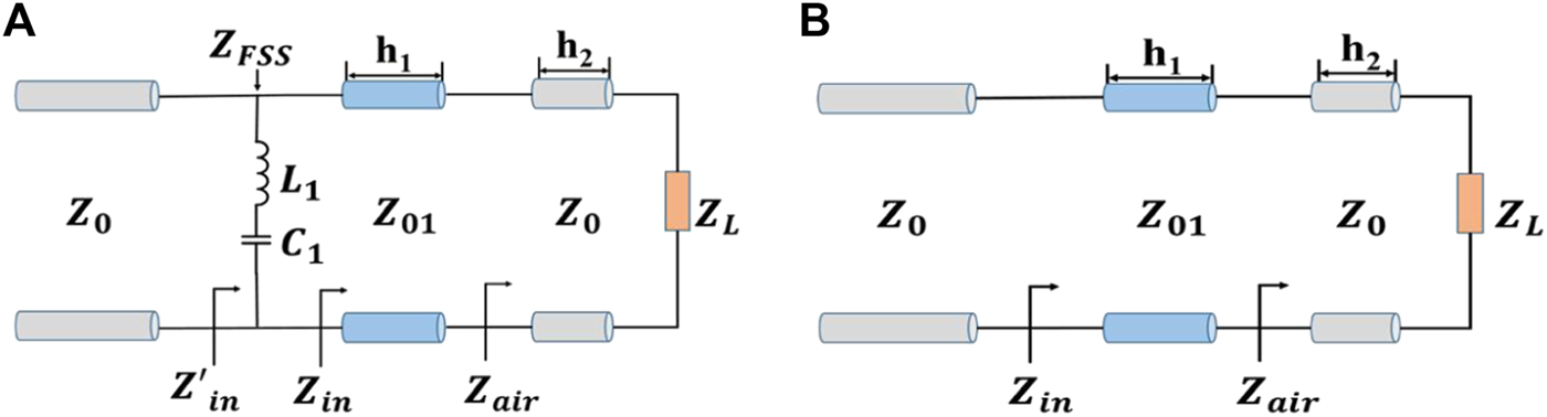
Equivalent circuits of the 1-bit polarization conversion unit cell (A) with substrates and (B) with an FSS.
In Eq. 1, , and Z0 = 377 Ω, where λ0 is the wavelength of the free space. We assume that the port impedance at the dielectric matching layer is Zin, which can be obtained by Eq. 2. Here, , and Z01 = 152 Ω.
Eq. 2 shows that the port impedance is related to the frequency, substrate thickness, and dielectric constant. By reasonably selecting the relevant parameters of the substrate, the port impedance can be made approximately equal to the free-space impedance over a wide frequency band. In our design, the reflection bandwidth is broadened when the matching substrates are loaded, as shown in Figure 3.
However, in some cases, the method of loading the dielectric matching layer fails to meet the design requirements. Hence, a frequency selective surface (FSS) is utilized instead of a dielectric substrate to introduce more design variables. As shown in Figure 1, a metal pattern with multiple split rings is designed. This pattern is not only easy to process, but also insensitive to polarization. The results shown in Figure 3 indicate that the bandwidth is further broadened after changing to the FSS structure. To accurately describe the bandwidth expansion process, an equivalent circuit with the FSS is shown in Figure 4B. The metal is equivalent to a series connection of inductance L1 and capacitance C1. Eq. 3 also demonstrates that the port impedance is related to the two variables of capacitance and inductance. Advanced Design System (ADS) software is used to calculate the equivalent circuit parameters. After optimization, L1 = 38 nH and C1 = 4.4 fF are obtained. The results of the equivalent circuit in Figure 5 show that the unit with the FSS can exhibit increased bandwidth owing to the new resonance point. Because the coupling effect between the FSS and underlying metal pattern is not considered in this equivalence, there are some deviations between the simulated and numerically calculated curves. However, the two curves are still in good agreement.
FIGURE 5
Reflection amplitudes from the CST simulation and equivalent circuit calculation.
2.3 Mechanism of Polarization Conversion and the 1-Bit Phase Response
To study the polarization conversion mechanism, we introduce a local coordinate system (uv-axes) with the u- and v-axes rotated with respect to the +y direction. In the following analysis, we consider that the incident plane waves propagate in the -z direction. The relationship between the incident and reflected electric fields can be expressed as Eref= REinc, where R is a reflection matrix. Therefore, in the uov coordinate system, it can be expressed as (Khan et al., 2019):where R is the reflection coefficient, the first subscript indicates the polarization of the reflected electric field, and the second subscript represents the polarization of the incident electric field. Because the incident plane waves are x-pol and y-pol, the incident and reflected electric fields in the xoy coordinate system can be expressed in terms of the reflection matrix of the u- and v-axes as follows:where Rot represents the rotation matrix . The vectors of the x- and y-polarized plane waves are denoted as and , respectively. We assume that the electric fields in the u and v directions do not convert to each other; thus, , with and . Then, according to Eq. 5, must be maintained to realize the conversion of x- to y-polarization (or vice versa). In other words, if the unit is designed to have the same amplitude and reverse phase of the reflection coefficients along the u- and v-axes, an excellent polarization conversion effect can be achieved. Consider the case where D1 and D3 are turned on and D2 and D4 are turned off as an example. When the incident waves are u- and v- polarized, from 9.98 to 11.9 GHz, the difference in reflection amplitudes is tiny, and the phase difference is within , as can be seen in Figure 6.
FIGURE 6
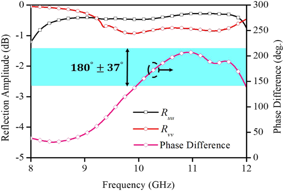
Simulation results of the reflection amplitudes and phase difference along the u and v directions.
Additionally, the surface currents can account for the difference in the u- and v-directions, as shown in Figures 7A,B at 10.5 GHz. When the plane wave is x-pol, the current distributions of the unit along the u- and v-axes are discrepant. In either case, the current mainly flows through the branches where the PIN diodes are turned off. Therefore, the resonant frequencies in the two directions are different, resulting in different phases.
FIGURE 7
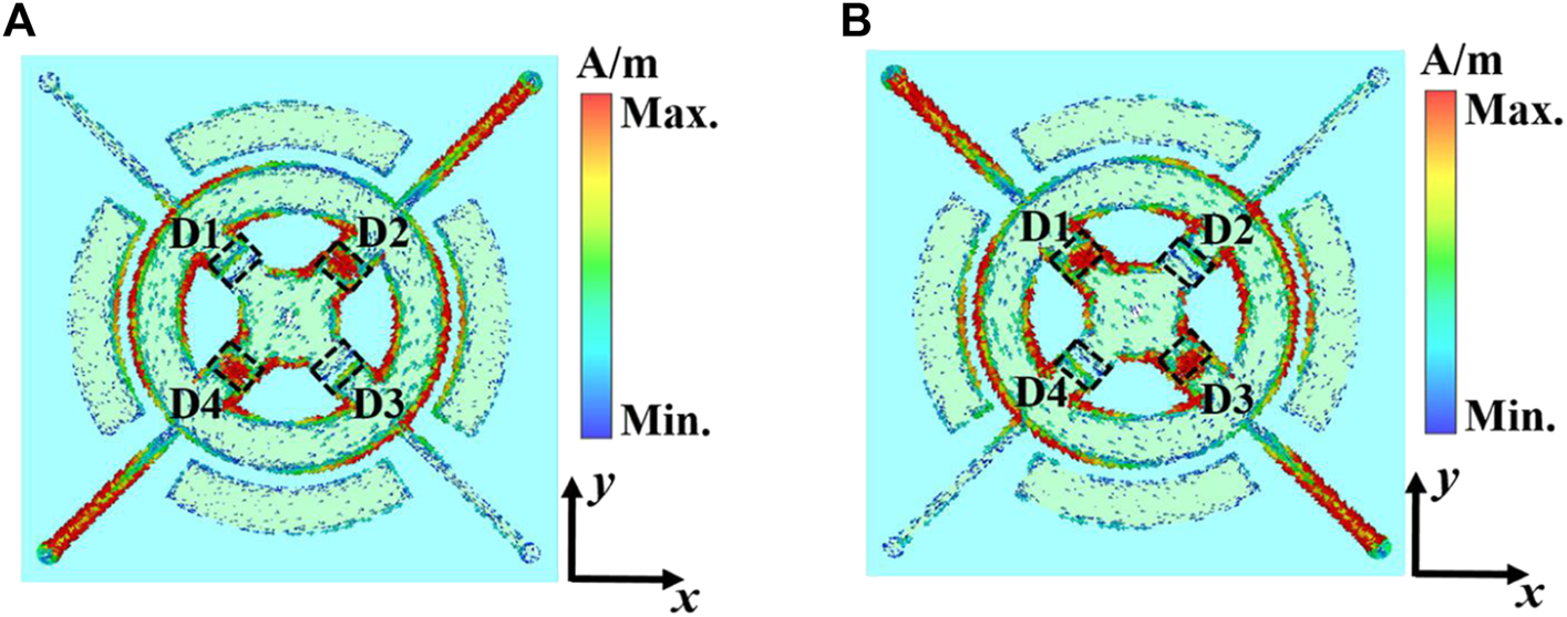
Current distributions at 10.5 GHz (A) when D1 and D3 are on and D2 and D4 are off, and (B) when D1 and D3 are off and D2 and D4 are on.
From the above analysis, the phases of the reflected electric field along the u- and v-axes are approximately out of phase, and this result is the basis for the 1-bit phase response. The incident electric field is assumed to be (Yetisir et al., 2016); then, the reflected electric field can be expressed as , as shown in Figure 8A. Here, the green diodes indicate on, and the purple diodes indicate off. When the operating states of the PIN diodes are switched, the electric field is out of phase in the u direction and remains unchanged in the v direction (Figure 8B). As a result, the reflected electric field can be expressed as . There is clearly a 1-bit phase response between these two cases.
FIGURE 8
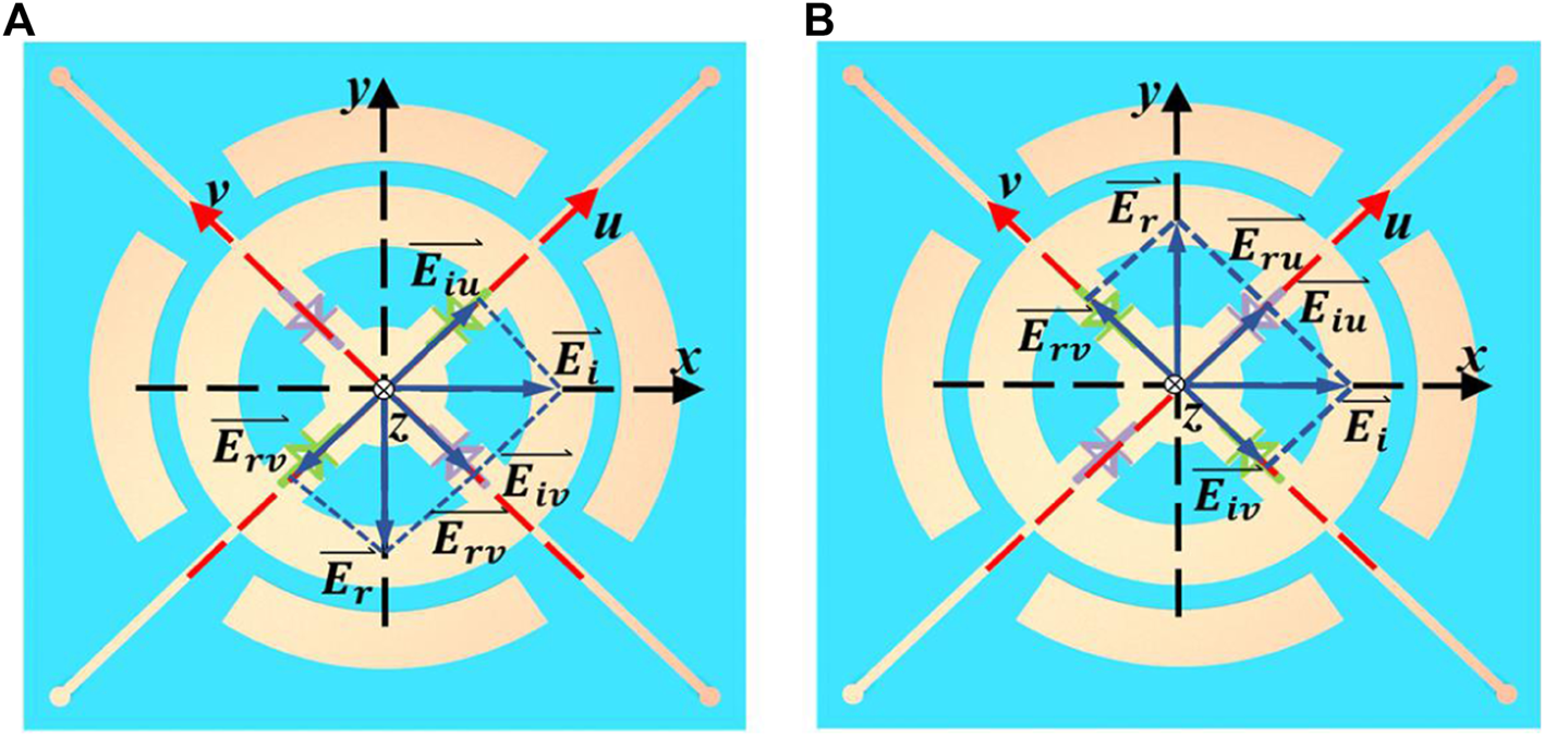
Schematic diagram of the synthesis and decomposition of the incident electric field and the reflected electric field under x-polarized incidence. The reflected electric field is along the (A)y and (B) -y directions.
3 Experiment Results
Based on the above design, a prototype composed of meta-atoms is fabricated by printed circuit board (PCB) technology, as shown in Figure 9. The entire measurement is performed in a microwave anechoic chamber, and the specific experimental setup can be found in Figure 10. Two vertically polarized horns are connected to the two ports of a vector network analyzer to receive and transmit EM waves. The sample should be placed at a suitable distance to satisfy the far-field conditions. To ensure that the metasurface and horns receive the maximum energy, the sample should be set directly in front of the horn and at the same height. A DC-stabilized voltage source provides driving voltages to control the turn-on and turn-off states of diodes.
FIGURE 9
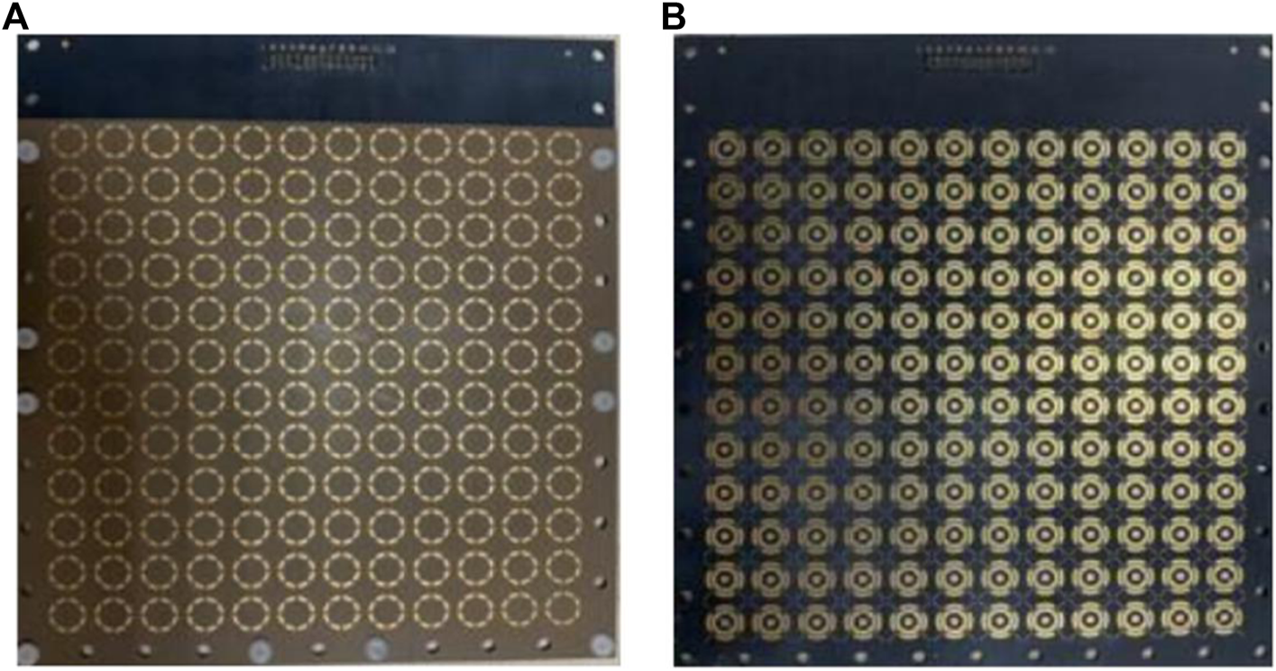
Manufactured prototype of the metasurface. (A) First metallic layer. (B) Second metallic layer.
FIGURE 10
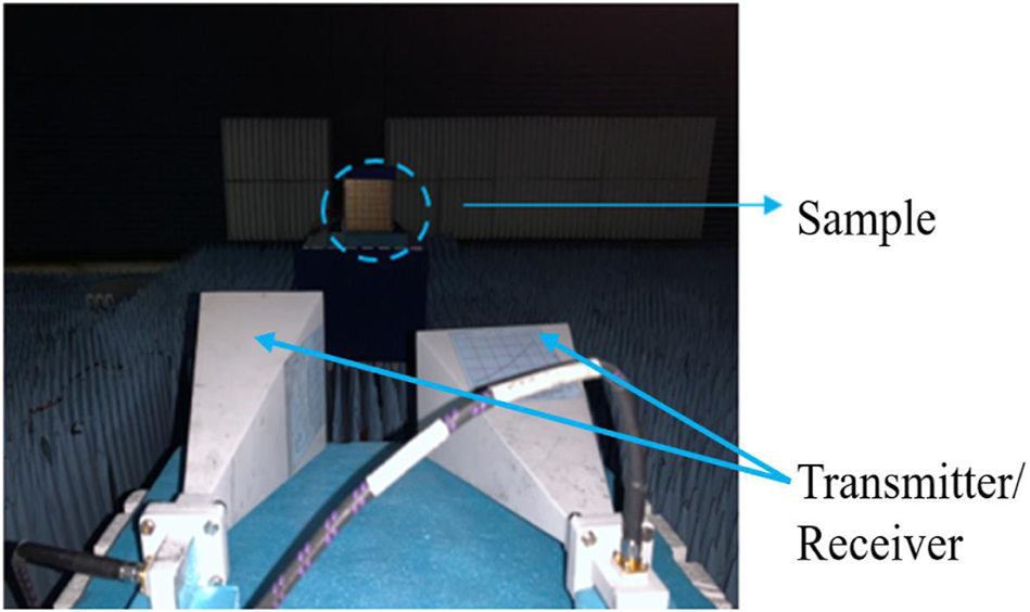
Experimental configurations in the microwave anechoic chamber.
In the environment setup above, we first measure the cross-polarized reflection amplitudes and phases of the sample under diode bias voltages of 0.9 V and −0.9 V. As a reference, we also measure the reflection amplitude of a metal plate of the same size as the sample at the same location. Consequently, the final phase difference can be obtained by comparing the phases for the two opposite voltages. Moreover, the reflection amplitudes of the measured sample are normalized to those of the metal plate.
The measured cross-polarized reflection amplitudes and phase differences are shown in Figure 11. When D1 and D3 are switched on while D2 and D4 are switched off, the reflection amplitude is above −1 dB in a wide bandwidth from 10.04 to 11.36 GHz. The maximum reflection amplitude is −0.19 dB. When D1 and D3 are switched off while D2 and D4 are switched on, the coding metasurface can achieve a low loss within 1 dB, covering almost the same bandwidth, and the minimum reflection loss is 0.56 dB. The amplitude difference between the two cases is within 0.5 dB. The phase difference between these two cases is in the X-band, as shown in Figure 11B. The measured results indicate that the coding metasurface can achieve polarization conversion and a 1-bit phase resolution over a wide bandwidth.
FIGURE 11
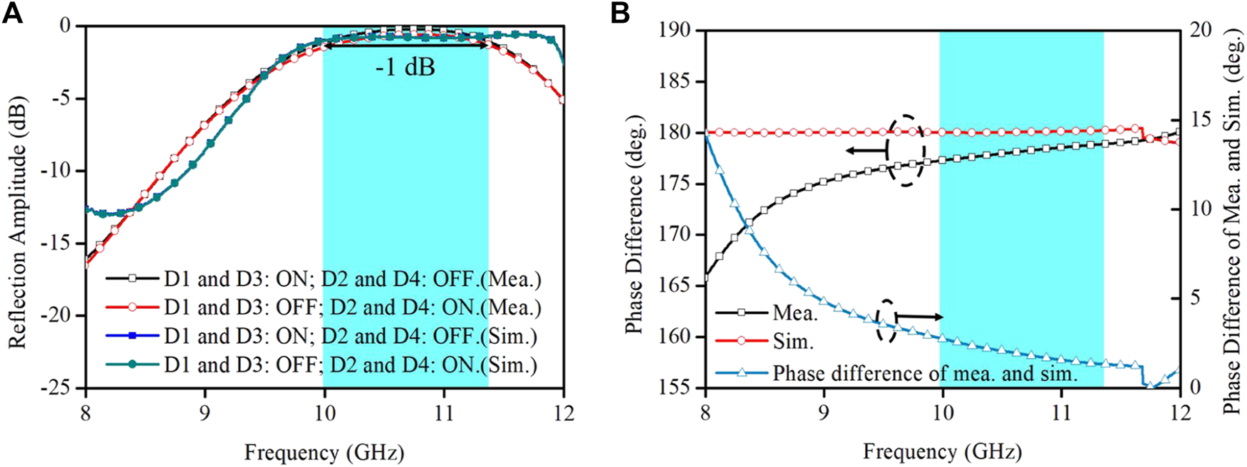
Simulated and measured cross-polarized reflection amplitudes (A) and phase differences (B).
The measurement results are consistent with the simulation results; however, there are still disparities. The measured reflection amplitude above −1 dB is shifted to higher frequency, and the bandwidth is reduced. Moreover, in the frequency band corresponding to an amplitude above −1 dB, the measured phase difference is approximately 5° smaller than the simulated phase difference. These differences can be attributed to the following reasons: 1) Instability of the dielectric constant of the dielectric substrate, 2) errors in the diode equivalent parameters during simulation, and 3) fabrication and measurement processes.
Finally, Table 1 summarizes recently reported metasurfaces that achieve polarization conversion and a 1-bit phase response. A comparison of the measurement results indicates that the unit proposed in this study has a wider bandwidth with a reflection amplitude above −1 dB and a lower loss.
TABLE 1
| Refs. | Measured operating bandwidth (GHZ) | Measured relative bandwidth (%) | Reflection amplitude (dB) |
|---|---|---|---|
| Yetisir et al. (2016) | 12.375–12.625 | Approx. 2 | −1 |
| This work | 10.04–11.36 | 12.3 | −1 |
Comparisons with previous literatures.
4 Conclusion
We present a multifunctional metasurface with polarization conversion and a 1-bit phase response with the advantage of a wide bandwidth. On the one hand, the main reason for polarization conversion is the different working conditions of the PIN diodes along uv-axes, resulting in a phase difference of approximately 180°. To further investigate this mechanism, we explain it from the perspective of the current. On the other hand, by changing the bias voltage from 0.9 V to −0.9 V, the synthetic total electric field is in the opposite direction, thus obtaining a 1-bit phase response. To extend the bandwidth, we have innovatively used the matching layer technique. Furthermore, we illustrate the effectiveness of this technique from the point of view of equivalent circuits. We also measure the sample and verify the performance of the metasurface. When D1 and D3 are switched on while D2 and D4 are switched off, the metasurface can achieve a polarization conversion amplitude above −1 dB over a 1.32 GHz bandwidth, and the maximum reflection amplitude is −0.19 dB. When D1 and D3 are switched off while D2 and D4 are switched on, the cross-polarized reflection loss of this unit is within 1 dB, and the bandwidth is 1.05 GHz. The minimum loss is 0.56 dB. The measurement results show that the unit has the performance of a 180° ± 15° phase response in a wide band with low loss. Another important performance metric of this metasurface is the achievement of 180 ± 15° in the X band. The excellent performance of this unit is conducive to its applications in radar detection, folded reflectarrays and other fields.
Statements
Data availability statement
The original contributions presented in the study are included in the article/Supplementary Material, further inquiries can be directed to the corresponding author.
Author contributions
WG and MC contributed equally to this work. MC carried out the analytical modeling, numerical simulations, sample fabrication, and measurements. WG and QC contributed to the preparation and writing of the manuscript. All authors discussed the theoretical and numerical aspects and interpreted the results.
Funding
This work is supported by the National Key Research and Development Pro-gram of China (2017YFA0700201, 2017YFA0700202, and 2017YFA0700203), the National Natural Science Foundation of China (61631007, 61571117, 61138001, 61371035, 61722106, 61731010, and 11227904), and the 111 Project (111-2-05).
Conflict of interest
The authors declare that the research was conducted in the absence of any commercial or financial relationships that could be construed as a potential conflict of interest.
Publisher’s note
All claims expressed in this article are solely those of the authors and do not necessarily represent those of their affiliated organizations, or those of the publisher, the editors and the reviewers. Any product that may be evaluated in this article, or claim that may be made by its manufacturer, is not guaranteed or endorsed by the publisher.
References
1
Baena J. D. Glybovski S. B. del Risco J. P. Slobozhanyuk A. P. Belov P. A. (2017). Broadband and Thin Linear-To-Circular Polarizers Based on Self-Complementary Zigzag Metasurfaces. IEEE Trans. Antennas Propagat.65, 4124–4133. 10.1109/tap.2017.2717964
2
Cameron T. R. Eleftheriades G. V. (2015). Analysis and Characterization of a Wide-Angle Impedance Matching Metasurface for Dipole Phased Arrays. IEEE Trans. Antennas Propagat.63, 3928–3938. 10.1109/tap.2015.2448231
3
Cheng Y.-F. Ding X. Shao W. Wang B.-Z. (2017). Planar Wide-Angle Scanning Phased Array with Pattern-Reconfigurable Windmill-Shaped Loop Elements. IEEE Trans. Antennas Propagat.65, 932–936. 10.1109/tap.2016.2632736
4
Davis J. A. Moreno I. Tsai P. (1998). Polarization Eigenstates for Twisted-Nematic Liquid-Crystal Displays. Appl. Opt.37, 937–945. 10.1364/ao.37.000937
5
Del Mastro M. Ettorre M. Grbic A. (2020). Dual-Band, Orthogonally-Polarized LP-To-CP Converter for SatCom Applications. IEEE Trans. Antennas Propagat.68, 6764–6776. 10.1109/tap.2020.2989868
6
Dussopt L. Moknache A. Saily J. Lamminen A. Kaunisto M. Aurinsalo J. et al (2017). A V-Band Switched-Beam Linearly Polarized Transmit-Array Antenna for Wireless Backhaul Applications. IEEE Trans. Antennas Propagat.65, 6788–6793. 10.1109/tap.2017.2723921
7
Encinar J. A. (2001). Design of Two-Layer Printed Reflectarrays Using Patches of Variable Size. IEEE Trans. Antennas Propag.49, 1403–1410. 10.1109/8.954929
8
Fernández O. Gómez Á. Basterrechea J. Vegas A. (2017). Reciprocal Circular Polarization Handedness Conversion Using Chiral Metamaterials. IEEE Antennas Wirel. Propag. Lett.16, 2307–2310. 10.1109/lawp.2017.2715830
9
Gao W. H. Chen M. Cheng Q. Shao R. W. Liang J. C. Gao Y. et al (2021). 1-bit Reconfigurable Transmitarray with Low Loss and Wide Bandwidth. New J. Phys.23, 065006. 10.1088/1367-2630/ac02de
10
Gao X. Han X. Cao W.-P. Li H. O. Ma H. F. Cui T. J. (2015). Ultrawideband and High-Efficiency Linear Polarization Converter Based on Double V-Shaped Metasurface. IEEE Trans. Antennas Propagat.63, 3522–3530. 10.1109/tap.2015.2434392
11
Han C. Zhang Y. Yang Q. (2017). A Novel Single-Layer Unit Structure for Broadband Reflectarray Antenna. Antennas Wirel. Propag. Lett.16, 681–684. 10.1109/lawp.2016.2598733
12
Huang C. Pan W. Ma X. Luo X. (2016). 1-Bit Reconfigurable Circularly Polarized Transmitarray in X-Band. Antennas Wirel. Propag. Lett.15, 448–451. 10.1109/lawp.2015.2451697
13
Ke J. C. Dai J. Y. Chen M. Z. Wang L. Zhang C. Tang W. et al (2021). Linear and Nonlinear Polarization Syntheses and Their Programmable Controls Based on Anisotropic Time‐Domain Digital Coding Metasurface. Small Struct.2, 2000060. 10.1002/sstr.202000060
14
Khan B. Kamal B. Ullah S. Khan I. Shah J. A. Chen J. (2020). Design and Experimental Analysis of Dual-Band Polarization Converting Metasurface for Microwave Applications. Sci. Rep.10, 15393. 10.1038/s41598-020-71959-y
15
Khan M. I. Khalid Z. Tahir F. A. (2019). Linear and Circular-Polarization Conversion in X-Band Using Anisotropic Metasurface. Sci. Rep.9, 4552. 10.1038/s41598-019-40793-2
16
Lei Z. Yang T. (2017). Converting State of Polarization with a Miniaturized Metasurface Device. IEEE Phot. Technol. Lett.29, 615–618. 10.1109/lpt.2017.2675453
17
Li W. Xia S. He B. Chen J. Shi H. Zhang A. et al (2016). A Reconfigurable Polarization Converter Using Active Metasurface and its Application in Horn Antenna. IEEE Trans. Antennas Propagat.64, 5281–5290. 10.1109/tap.2016.2620484
18
Lin B. Lv L. Guo J. Liu Z. Ji X. Wu J. (2020). An Ultra-wideband Reflective Linear-To-Circular Polarization Converter Based on Anisotropic Metasurface. IEEE Access8, 82732–82740. 10.1109/access.2020.2988058
19
Lin B-q. Huang W.-z. Lv L-t. Guo J.-x. Huang S.-q. Zhu R. (2018). Ultra-Wideband Linear-to-Circular Polarization Conversion Realized by an 8-Shaped Metasurface. Plasmonics14.
20
Liu K.-Y. Wang G.-M. Cai T. Li H.-P. Li T.-Y. (2021). Conformal Polarization Conversion Metasurface for Omni-Directional Circular Polarization Antenna Application. IEEE Trans. Antennas Propagat.69, 3349–3358. 10.1109/tap.2020.3037647
21
Masson J.-B. Gallot G. (2006). Terahertz Achromatic Quarter-Wave Plate. Opt. Lett.31, 265–267. 10.1364/ol.31.000265
22
Shah S. M. Q. A. Shoaib N. Ahmed F. Alomainy A. Quddious A. Nikolaou S. et al (2021). A Multiband Circular Polarization Selective Metasurface for Microwave Applications. Sci. Rep.11, 1774. 10.1038/s41598-021-81435-w
23
Sun S. Jiang W. Gong S. Hong T. (2018). Reconfigurable Linear-To-Linear Polarization Conversion Metasurface Based on PIN Diodes. Antennas Wirel. Propag. Lett.17, 1722–1726. 10.1109/lawp.2018.2864797
24
Tao Z. Wan X. Pan B. C. Cui T. J. (2017). Reconfigurable Conversions of Reflection, Transmission, and Polarization States Using Active Metasurface. Appl. Phys. Lett.110, 121901. 10.1063/1.4979033
25
Wang Z. Dong Y. (2020). Low-Profile Omnidirectional WIFI Antennas with Pattern Reconfigurability Inspired by Meta-Resonators. IEEE Trans. Antennas Propag.68 (10), 6935–6942. 10.1109/tap.2020.2995431
26
Wu R. Y. Li Y. B. Wu W. Shi C. B. Cui T. J. (2017). High-Gain Dual-Band Transmitarray. IEEE Trans. Antennas Propagat.65, 3481–3488. 10.1109/tap.2017.2705074
27
Xu J. Li T. Lu F. F. Wang S. M. Zhu S. N. (2011). Manipulating Optical Polarization by Stereo Plasmonic Structure. Opt. Express19, 748–756. 10.1364/oe.19.000748
28
Yetisir E. Ghalichechian N. Volakis J. L. (2016). Ultrawideband Array with 70° Scanning Using FSS Superstrate. IEEE Trans. Antennas Propagat.64, 4256–4265. 10.1109/tap.2016.2594817
29
Zheng Q. Guo C. Ding J. (2018). Wideband Metasurface-Based Reflective Polarization Converter for Linear-To-Linear and Linear-To-Circular Polarization Conversion. Antennas Wirel. Propag. Lett.17, 1459–1463. 10.1109/lawp.2018.2849352
30
Zou M. Su M. Yu H. (2020). Ultra-broadband and Wide-Angle Terahertz Polarization Converter Based on Symmetrical Anchor-Shaped Metamaterial. Opt. Mater.107, 110062. 10.1016/j.optmat.2020.110062
Summary
Keywords
metasurface, polarization conversion, 1-bit reflection phase, PIN diodes, X band
Citation
Gao WH, Chen M, Cheng Q and Cui TJ (2022) A 1-Bit Coding Metasurface With Polarization Conversion in X-Band. Front. Mater. 9:914937. doi: 10.3389/fmats.2022.914937
Received
07 April 2022
Accepted
21 April 2022
Published
05 May 2022
Volume
9 - 2022
Edited by
Bin Yang, Shanghai Jiao Tong University, China
Reviewed by
Jinhui Shi, Harbin Engineering University, China
Junming Zhao, Nanjing University, China
Updates
Copyright
© 2022 Gao, Chen, Cheng and Cui.
This is an open-access article distributed under the terms of the Creative Commons Attribution License (CC BY). The use, distribution or reproduction in other forums is permitted, provided the original author(s) and the copyright owner(s) are credited and that the original publication in this journal is cited, in accordance with accepted academic practice. No use, distribution or reproduction is permitted which does not comply with these terms.
*Correspondence: Qiang Cheng, qiangcheng@seu.edu.cn
†These authors have contributed equally to this work
This article was submitted to Metamaterials, a section of the journal Frontiers in Materials
Disclaimer
All claims expressed in this article are solely those of the authors and do not necessarily represent those of their affiliated organizations, or those of the publisher, the editors and the reviewers. Any product that may be evaluated in this article or claim that may be made by its manufacturer is not guaranteed or endorsed by the publisher.