 Liting Liu
 Minshu Du
 Feng Liu1,2*
- 1Analytical and Testing Center, Northwestern Polytechnical University, Xi’an, China
- 2State Key Laboratory of Solidification Processing, Northwestern Polytechnical University, Xi’an, China
Carbon fiber reinforced polymer composites (CFRPs) have excellent properties, e.g., low density, high-temperature resistance, high specific modulus, and high specific strength, and are widely used in aerospace and civil industries. CFRP comprises carbon fiber, polymer matrix, and the interface between them. The microstructure, chemical composition, bonding mode, and interfacial bonding strength of the CFRPs interface greatly influence the mechanical properties and failure behavior of CFRPs. Accordingly, the deep, systematic and nuanced characterization of the microstructure and properties of the interfaces is one of the critical problems in the research field of CFRPs. In this paper, various microscopic characterization methods of CFRPs interface micromorphology, microstructure, chemical composition and mechanical properties developed in recent years are reviewed. For example, scanning electron microscopy (SEM), transmission electron microscopy (TEM), atomic force microscopy (AFM), X-ray photoelectron spectroscopy (XPS), Raman spectroscopy (Raman), nanoindentation and other advanced analytical characterization techniques, as well as the application of newly developed microscopic in situ mechanical testing methods in the interface characterization of CFRPs. The prospect and trend of interface microscopic characterization technology of CFRPs have also been prospected.
1 Introduction
Carbon fiber reinforced polymer composites (CFRPs) are composite materials with carbon fiber (CF) as reinforcement and polymer as the matrix, accounting for more than 90% of the total CF composites market share. Unlike polymer composites that use traditional fibers, such as glass fibers or aramid fibers, CFRPs offer excellent performance in terms of light weight and high strength. CFRPs are not only lightweight, but also have higher strength and higher hardness per unit weight than glass fiber polymer composites. According to the source of the precursor, CFs can be divided into polyacrylonitrile (PAN)-based CFs, pitch-based CFs, and viscose-based CFs (Zhang et al., 2021a). The polymer matrix is usually classified into two types, thermosetting resins and thermoplastic resins. Commonly used thermosetting resins include epoxy, bismaleimide, polyimide and phenolic resins. Commonly used thermoplastic resins are polyethylene, nylon, polytetrafluoroethylene and polyetheretherketone. CFRPs have high specific strength and modulus, low density, low coefficient of thermal expansion, corrosion and abrasion resistance, fatigue resistance, good electrical conductivity, good electromagnetic shielding performance, accessibility to large-area integral molding and other excellent properties. Therefore, CFRPs have been used extensively in aerospace, navigation, construction, light industry, as well as other areas (Pilato and Michno, 1994; Zheng, 2009; Dang et al., 2012; Park and Seo, 2012; Wichita State University NIAR, 2012; Jin et al., 2013; Jin and Park, 2015; Park et al., 2015; Kim et al., 2016; Nabil, 2016; Wang et al., 2016; Lin, 2022).
The interface of CFRP is the intermediate phase connecting the reinforced CFs and the polymer matrix, a unique and essential component of the composites, and transferring the applied load from the polymer matrix to the reinforced CFs. The microstructure, composition, bonding mode and interface bonding strength of CFRP interface significantly impact the overall performance of composites, affecting the mechanical properties, environmental stability and functional expression. By enhancing the matching of reinforced CFs, polymer matrix and interface, the best interfacial bonding strength together with the best mechanical properties can be obtained. Therefore, CFRPs’ interface structure and optimization design have attracted much attention, and the inner mechanical interface or failure mechanism are also frontiers in materials science (Dawood et al., 2015; Liu et al., 2015; Lu and Youngblood, 2015; Dhieb et al., 2016; Luo et al., 2016; Xu et al., 2016; Yamamoto et al., 2016; He et al., 2020; Wu et al., 2021).
The interfacial microstructure and chemical composition significantly influence the macroscopic properties of CFRP, so it is essential to conduct in-depth, systematic, detailed research on the interfacial properties. A thorough understanding of the interface properties should include the examination of the surface properties of CF and polymer matrix and the transition zone (interface) between the two. However, the interface size of CFRP is mainly at the micron or even nanometer scale, and the microstructure and chemical composition of the interface is very complex, so the microscopic characterization of the interface in CFRP is challenging. With the emergence and utilization of various new characterization methods and instruments in recent years, it is possible to conduct in-depth research on the micromorphology, microstructure, chemical composition and mechanical properties of the interface (Figure 1). This provides an excellent theoretical basis for effectively controlling the interfacial phase structure, optimizing the structural design and mechanical properties of CFRPs, and promoting the engineering application of CFRPs. In this paper, the microscopic characterization methods of CFRPs are reviewed to provide theoretical guidance for optimizing the interface and improving the mechanical properties of CFRPs.
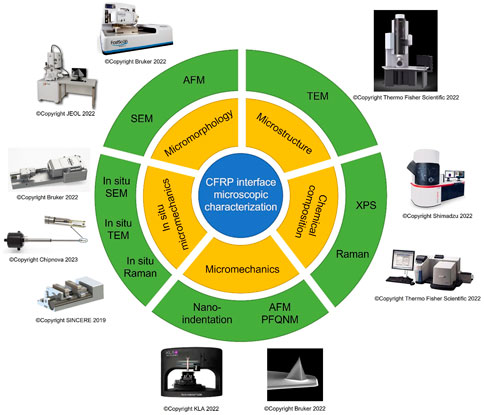
FIGURE 1. Schematic diagram of interface microscopic characterization methods of CFRPs.
2 Microscopic characterization of CFRP interface
2.1 Characterization of CFRP interface micromorphology
2.1.1 Scanning electron microscopy (SEM)
SEM is a commonly applied method to characterize the surface morphology of composite materials, with a resolution of up to 1 nm. SEM can be utilized to observe the fracture surface morphology of the interface. Typically, the observation object of interfacial fracture surface morphology includes the interface cross-section and the exposed CF reinforcer surface and polymer matrix surface after debonding. Secondary electron imaging in SEM is best suited for observing interface morphology and is often used as the preferred method for a rough understanding of interface structure.
Observation of interface fracture surface morphology is helpful for a rough understanding of interface structure. According to the interface morphology, combined with the properties of the CFs and polymer, molding process parameters and other information, it can help to determine whether there is a specific crystalline state, amorphous state, other aggregated state states and components of interfaces. It is also possible to give reasonable estimates of problems related to the mechanical behavior of CFRP. For example, the degree of bonding between the CFs and polymer, the mode of failure by force, etc. Indeed, it should also be combined with other testing techniques for mutual verification to obtain definite conclusion.
Jain et al. (2021) used field emission-SEM (FE-SEM) to analyze the fracture surface morphology after tensile testing of carbon fiber-reinforced epoxy (CF EP) composites and graphene nanoplatelet (GNP) CF EP composites (Figure 2A). The CFs of CF EP composite showed no epoxy traces on the fractured surface. After adding GNP, wrinkles appeared on the fibers, indicating that GNP was covered and the interfacial adhesion between CFs and epoxy was better. Figure 2B showed the morphology of CFs pull-out on the transverse-sectional fracture surface of CF EP composites, which was used to investigate the interfacial bonding quality. CF EP showed the separation of CFs from the epoxy and the complete deep holes formed by pulling out of a bundle of CFs (Figure 2B, a). This confirmed the weak interface binding of CFs to the epoxy in CF EP composites. The minimal gaps between carbon fibers and reinforced epoxy composites were observed in Figure 2B, b. The morphology and roundness of the pores were irregular and rough, demonstrating an apparent interface binding between CFs and reinforced epoxy matrix.
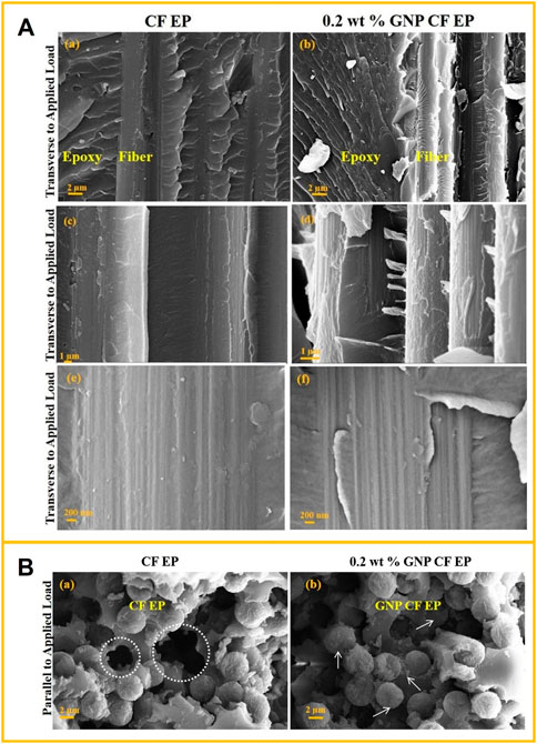
FIGURE 2. (A) FE-SEM images of fracture surfaces of (a, c, e) CF EP, (b, d, f) GNP CF EP, in the transverse direction to applied tensile load. Reprinted with permission from (Jain et al., 2021). Copyright 2021 Springer Nature. (B) FE-SEM images of fracture surfaces of (a) CF EP and (b) GNP CF EP in the direction parallel to the applied load. Reprinted with permission from (Jain et al., 2021). Copyright 2021 Springer Nature.
Identifying the fracture morphology of CFRP helps analyze the mechanical properties of composites. Liang et al. (2021) successfully prepared a CF-reinforced epoxy resin composite with the structure eagle feather-like (Figure 3A). With the increment of CF content (from 0.1 wt% to 0.4 wt%), the impact toughness and tensile strength of CF-reinforced epoxy resin composites first increased and follow decreased. As shown in Figure 3B, the change in CF content obviously affected the fracture morphology of CF-reinforced epoxy resin composites. Hackly fracture morphology of cracks in the epoxy resin matrix, CF1 (0.1 wt%), and CF2 (0.2 wt%) bands were shown in Figures 3B, a–c. As the CF content increased, the number of cracks significantly increased. On the fracture morphology of CF3 (0.3 wt%), the microfluidic crack spread along the loading direction (Figure 3B, d). The number of cracks in Figure 3B, e was small, and the CF4 (0.4 wt%) fracture appearance was relatively smooth. The extraction and breaking of carbon fibers effectively improved tensile strength.
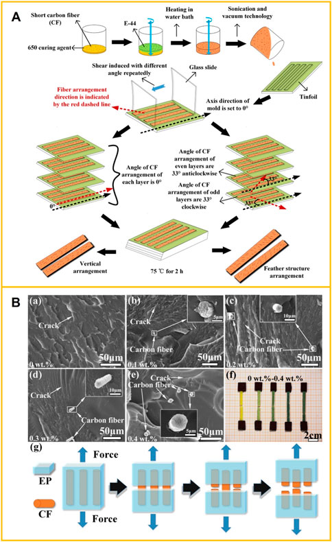
FIGURE 3. (A) Manufacturing process of carbon fiber reinforced epoxy resin composites. Reprinted with permission from (Liang et al., 2021). Copyright 2021 IOP Publishing Ltd. (B) Tensile fracture appearance of short carbon fiber reinforced epoxy resin composites with various carbon fiber content (a) 0 wt%, (b) 0.1 wt%, (c) 0.2 wt%, (d) 0.3 wt%, (e) 0.4 wt%, (f) tensile test samples and (g) tensile resistance mechanism. Reprinted with permission from (Liang et al., 2021). Copyright 2021 IOP Publishing Ltd.
2.1.2 Atomic force microscopy (AFM)
AFM is widely used for surface topography characterization and surface properties analysis of materials (Butt et al., 2005). AFM studies substances’ surface structure and properties by detecting the feeble interatomic interaction forces between sample surface and probe. AFM can obtain high-resolution images of surface structures from a few nanometers to hundreds of microns (resolution up to 0.1 nm). High-precision and high-sensitivity quantitative analysis of microscopic two-dimensional morphology, three-dimensional morphology, height, roughness, particle size distribution, material microstructure, material properties and other information can be obtained. AFM is also a powerful tool for characterizing mechanical properties (such as hardness, modulus, viscoelasticity, etc.) and solid matter’s electrical and magnetic properties in the local region (Sokolov et al., 2006; Xia et al., 2014; Variola, 2015; Serri et al., 2017).
AFM’s most common imaging modes are topography and phase images (Downing et al., 2000). The topography can be used to display the interface profile of the transverse or longitudinal cross-section of the composites, observe the surface of the CF reinforcement, including the morphologies of the original and modified surfaces of CFs and the surface (interface) morphologies of CFs pulled from composites. Based on this, the interface structure and performance under different surface treatments and processing conditions can be inferred or judged, and the interface bonding mechanism can be explored. Unlike SEM, AFM can describe the topography of CF surface from a three-dimensional scale and quantitatively determine various parameters describing surface roughness. Phase images can reveal the surface and subsurface organization, such as composition, morphology, distribution, and aggregate structure. The topography and phase images can reflect the microstructure of the CFRP interface. AFM tests work well in the air, under liquid, or in a vacuum and are environmentally friendly. When detecting the surface topography (height change), CFRP does not need special treatment, which can avoid possible damage to the interface structure during the sample preparation process. To detect the microstructure of the interface region, such as crystalline structure or other microscopic aggregated structural units, the surface must be ground and polished or cut flat with an ultramicrotome.
Wang and Hahn, (2007) first developed a method to characterize CFRP directly by combining height and phase AFM images. AFM was used to observe the carbon fiber sheath-core structure, the fiber-resin interface’s morphology, and the interface’s influence by damp heat conditions. It was shown that the hygroscopic and heat treatment caused the matrix to expand and shrink significantly, but there was no quantitative data analysis to describe this change.
Yang et al. (2020) established an AFM quantitative analysis method to assess the effects of thermal and hygrothermal treatment on the interfacial adhesion property of CFRP based on the shrinkage degree of the resin matrix (Figure 4). Eq. 1 gave the definition of the index ΔY of resin shrinkage extent of CFRPs after treatment. The interfacial properties of stability and linear constraint regions were characterized; the greater the shrinkage of the resin matrix, the weaker the interfacial adhesion in CFRP.
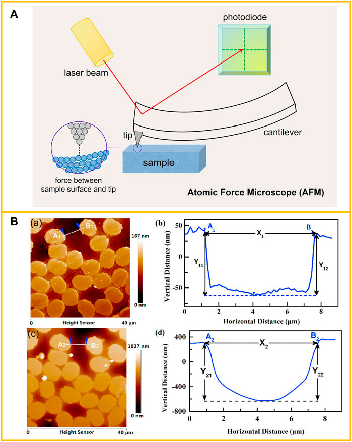
FIGURE 4. (A) Illustration of an AFM operating principle. (B) The AFM topography and height line profiles of a cross-sectional composite. (a) AFM topography before treatment; (b) height line profile of A1B1 before treatment; (c) AFM topography after treatment; (d) height line profile of A2B2. (Taking a hygrothermal treatment sample for example.) Reprinted with permission from (Yang et al., 2020). Copyright 2020 Elsevier Ltd.
2.2 Characterization of CFRP interface microstructure
2.2.1 Transmission electron microscopy (TEM)
TEM is a compelling means of characterizing the matter structure at the microscopic scale. TEM imaging has an extremely high resolution (about 0.1 nm), and spherical aberration TEM can even reach the pm level. TEM can visually observe the surface morphology of CF, distinguish the crystalline and amorphous regions in the sample, measure the thickness of the interface, and obtain the lattice or even the molecular and atomic image of CFRP. The main working modes of TEM include observation of transmission electron image and analysis of selected area electron diffraction (SAD) patterns, characteristic energy dispersive X-ray spectroscopy (EDX), and energy loss spectroscopy (EELS). Transmission electron image observation and SAD pattern analysis mainly reveal the interface region’s crystallography and other aggregated structures. In contrast, EDX and EELS are mainly used for the composition analysis of the interface region.
In general, TEM is an effective method to detect the microstructure of the interface. However, for CFRP, due to the vast difference in mechanical and physical properties between CF and polymer, it is challenging to prepare intact film specimens that contain fiber, matrix, and interfacial regions by conventional ultra-thin sectioning technology and ion thinning technology. Therefore, although TEM has been widely used in the interface microstructure analysis of fiber-reinforced metal matrix composites, ceramic matrix composites, carbon-carbon composites, etc., its application in CFRP is limited (Guigon and Klinklin, 1994; Wu et al., 2014). With the development of focused ion beam (FIB) technology, using FIB etching to prepare TEM samples has become an increasingly common method for some particular samples. Thus, a new solution is provided for TEM sample preparation of CFRPs.
Wu et al. (2015) used three techniques to prepare TEM samples (FIB, ion beam (IB) etching, and ultramicrotomy (UM)) and analyzed the interphase of carbon fiber/epoxy composites by TEM. In contrast, UM tended to damage and deform the interphase, and the uneven thickness of IB etched sample was not conducive to quantitative chemical analysis. The sample preparation effect of FIB was best, and a complete interphase with relatively uniform thickness can be prepared (Figures 5A, B). The chemical analysis of interphase was studied in detail by EELS (Figure 5C). The results showed that the width of the interphase region was 200 nm, the ratio of O/C increased from 10% to 19%, and the ratio of N/C was maintained at about 3%.
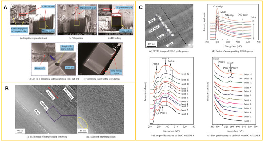
FIGURE 5. (A) Series of SEM images visualizing the sample preparation process by FIB of T300/epoxy composite longitudinal direction. Reprinted with permission from (Wu et al., 2015). Copyright 2015 Elsevier B.V. (B) The TEM image of the FIB-produced composite shows three regions: fiber, interphase, and epoxy resin. Reprinted with permission from (Wu et al., 2015). Copyright 2015 Elsevier B.V. (C) EELS spectra analysis of the interphase region in the energy loss range of C K-, N K-, and O K-edges. Reprinted with permission from (Wu et al., 2015). Copyright 2015 Elsevier B.V.
2.3 Characterization of CFRP interface chemical composition
2.3.1 X-ray photoelectron spectroscopy (XPS)
X-ray photoelectron spectroscopy (XPS), a commonly used surface analysis method in material analysis, is also called electron spectroscopy for chemical analysis (ESCA). With high surface sensitivity, XPS is mainly applied in the qualitative and quantitative detection of elements on the surface and interface of solid materials, and the analysis of different chemical states of elements. It is often used to analyze the chemical composition, chemical states of elements, and electronic states on the surface and interface of carbon fiber, chemical functional groups, and the changes before and after chemical modification, and then to study their influence on the interface between fiber and matrix. It can also cooperate with other technical means, such as ion beam etching and angle resolution XPS, to obtain chemical information at different depths and conduct in-depth research on interfaces.
Nakayama et al. (1990) used XPS to characterize chemically modified CFs in the gas phase. The changes in carbon structure and the number of functional groups introduced by surface oxidation of CFs were investigated. Ryu et al. (1999) employed an electrochemical treatment on high-strength CFs by increasing electric current density in an aqueous ammonium carbonate solution. The changes in surface functional groups were characterized by XPS, and the optimal (O1s + N1s)/C1s ratio was obtained to determine the appropriate treatment method. It was beneficial to add CFs to the polar organic matrix, thereby improving the interlayer shear strength of the synthetic CFRP.
Viswanathan et al. (2001) used core and valence band XPS to research the interfacial interaction between PAN-based IM7 CFs and thermoplastic polyimide resin Avimid K3B. The data indicated that a definite chemical interaction occurred between K3B and electrochemically oxidized IM7 fibers. Based on the chemical shift of the core region and the differences in the valence band region in the XPS results, the possible principles of the interaction between fiber and resin were speculated.
Park and Jang, (2003) coated the CF surfaces with a Ni-P layer for interface modification, which improved the impact resistance of CF-reinforced epoxy composites. The results of XRD and XPS tests explained the possible reasons (Figure 6). The increase of NiP2, Ni3P, and Ni metal in the Ni-P coating of CFs led to the increment of microcrystalline and amorphous phases, which increased the crack propagation path and adsorption energy, and finally reduced the stress concentration and improved the impact performance of the composite system.
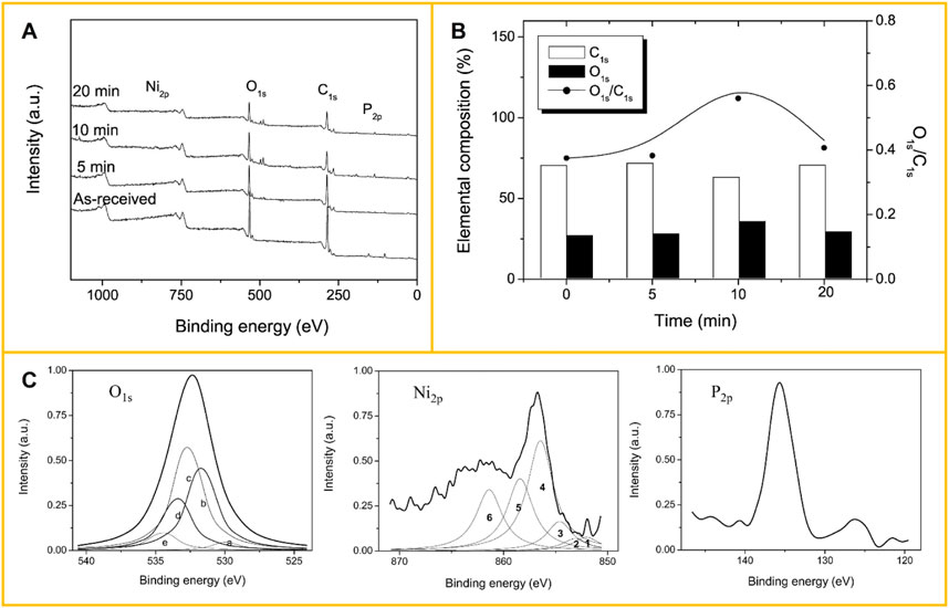
FIGURE 6. (A) XPS spectra of the Ni-P deposited carbon fibers as a function of the plating time. Reprinted with permission from (Park and Jang, 2003). Copyright 2003 Elsevier Science (United States). (B) Elemental composition and O1s/C1s ratio of non-treated and nickel-plated carbon fibers. Reprinted with permission from (Park and Jang, 2003). Copyright 2003 Elsevier Science (United States). (C) High-resolution spectra of O1s, Ni2p, and P2p for the Ni-P deposited carbon fibers (10 min): (a) NiO, (b) C=O or -OH, (c) O-C-O, (d) P2O5, (e) -C-O; (1) Ni metal, (2) Ni-P (Ni2P, NiP2, etc.), (3) NiO, (4) Ni-C, (5) Ni metal, and (6) Ni2O3 groups. Adapted with permission of (Park and Jang, 2003). Copyright 2003 Elsevier Science (United States).
2.3.2 Raman spectroscopy (Raman)
Raman spectroscopy is one of the most powerful methods to study the structure of matter. Its main functions in exploring the microstructure of materials include identifying constituent compounds, qualitative and quantitative analysis of components, molecular structure, crystallographic structure analysis, and determination of molecular orientation. The development of microscopic Raman spectroscopy has made it possible to analyze materials in micro-regions, and the progress of tip-enhanced Raman spectroscopy (TERS) has increased the spatial resolution from the micron level to the nanometer level, which plays a decisive role in the study of the interface microstructure of composite materials. Raman spectrometer is easy to operate, without special sample preparation, and can be used for quick analysis of points, lines, surfaces, and imaging to obtain more sample information.
Raman spectroscopy can determine the size and order of carbon grains on the interface and surface of CFs (Yang, 2010). CF usually shows two main peaks in its first-order Raman scattering, a G peak at ∼1,580 cm−1 and a D peak at ∼1,360 cm-1. The existence of the G peak is evidence that the fiber has a graphite crystal structure, while the D peak can reflect the size of the graphite grain, that is, the degree of structural disorder. The intensity ratio of Raman peak D to peak G, R = ID/IG, is sensitive to CF’s structural disorder, and CF’s grain size can be calculated. The peak width also indicates the order/disorder degree of the CF structure, and the peak width (half-height width) of peak D and peak G become more expansive with the increase of structural disorder degree. The Raman spectra of the interface can also judge the formation and distribution of the components on the CF interface and surface, as well as the morphological structure of the components.
Fei et al. (2018) grew aligned ZnO nanorods that were chemically bonding on carbon fabric to form a multi-scale reinforcing polymer composite. The carbon fabrics with or without aligned ZnO nanorods were characterized by Raman spectroscopy, and peaks at 330 cm−1, 441 cm−1, and 1,130 cm−1 confirmed that ZnO had been modified on the CF surface. Fu et al. (2020) put CF/epoxy microdroplet composite exposed under UV irradiation and compared the Raman spectra of the aromatic group, methyl group, epoxy ring and aromatic ring under different times by micro-Raman spectroscopy.
Zheng et al. (2020) modified renewable cardanol onto CF surfaces by in situ polymerization to strengthen the fiber-matrix interface, and Raman spectroscopy was used to analyze untreated CF, CF-OH, and CF-cardanol surface structures (Figure 7A). The D band (∼1,345 cm−1), A band (∼1,500 cm−1), and G band (∼1,590 cm−1) were three large bands in Raman spectroscopy of untreated and modified fibers. The A band represented amorphous forms of carbon or interstitial defects (Li et al., 2017; Chen et al., 2018). The change of ID/IG value before and after modification of CF was used to characterize the change in the order degree of graphite microcrystals on the fiber surface, to verify the effect of modification treatment.
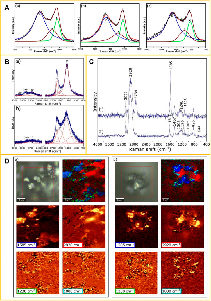
FIGURE 7. (A) Raman spectra and curve fitting for the CFs: (a) untreated CF, (b) CF-OH, and (c) CF-cardanol. Reprinted with permission from (Zheng et al., 2020). Copyright 2020 MDPI (Basel, Switzerland). (B) Raman spectrum (a) of graphene oxide (GO) and (b) of the virgin carbon fibers (CFs). Adapted with permission of (Florek et al., 2021). Copyright 2021 MDPI (Basel, Switzerland). (C) Raman spectra of (a) epoxy resin and (b) graphene oxide particle. Reprinted with permission from (Florek et al., 2021). Copyright 2021 MDPI (Basel, Switzerland). (D) Raman images of (a) the reference CFRP composite and (b) the CFRP sample with 0.3% GO addition. Reprinted with permission from (Florek et al., 2021). Copyright 2021 MDPI (Basel, Switzerland).
Florek et al. (2021) added graphene oxide nanoparticles (GO) to a polymer matrix to improve adhesion between CF and epoxy resin. Raman spectroscopy was used to study the composite’s structure and identified chemical bonds between the composite’s individual components. Raman imaging (Figures 7B–D) confirmed that GO was an intermediate connection between the laminate substrates, connecting with the epoxy resin matrix by hydrogen bonding, and reinforcing by chemical bonding formed between GO and CF.
2.4 Characterization of CFRP interface mechanical properties
2.4.1 Characterization of interface bonding strength
The interface between CFs and polymer matrix significantly influences CFRP’s mechanical properties (Schultz et al., 1987; Schultz and Lavielle, 1989; George et al., 2001; Gan, 2009). Because the interface is an important medium for external stress on the polymer matrix transfer to CF, good bonding or interaction at the interface is essential to achieve high shear and off-axis strength of CFRP. (Ismail and Vangsness, 1988; Park et al., 2000; Totry et al., 2010; He et al., 2017). Improving the interface properties between polymer matrix and CFs, can be achieved by increasing the roughness of CFs surface or depositing a transition layer on CFs surface, both of which are currently considered effective.
In CFRP, the adequate bonding between CFs and polymer matrix guarantees the excellent performance of the composites. The higher the interface bonding strength between CFs and polymer matrix in the composites, the more conducive it is to the transfer of stress between the CFs-polymer matrix, and the mechanical properties of the obtained composites are better. However, the interfacial bonding strength is not the higher the better, because too high interfacial bonding strength can quickly reduce the composites’ toughness.
Since the interfacial strength of fiber-matrix is crucial to the performance of CFRP, the measurement and analysis of interfacial strength is a key step in the custom design of composite materials. The characterization of the interfacial bonding strength of composites can be carried out from both micro and macro levels: microscopic testing refers to the measurement of the interfacial shear strength (IFSS) of CFRPs by fiber pull-out (Zhandarov and Mäder, 2005; Jones et al., 2014; Zheng et al., 2016), micro-bond (Nishikawa et al., 2008; Krishnan, 2017), fiber push-out (Liang and Hutchinson, 1993; Lin et al., 2001; Sha et al., 2013) and fiber fragmentation methods (Gong et al., 2001; Kim and Nairn, 2002; Yilmaz, 2002; Zhao et al., 2017), in which a single fiber in a carbon fiber bundle is used as the research object. In the three methods of fiber pull-out, micro-bond, and fiber push-out, the external load will directly act on the single carbon fiber, while the external load in the fiber fragmentation method is to load the polymer matrix. Among them, the experimental test of micro-bond is a reliable method for quantitatively determining the interfacial bonding strength of CFRP.
Macroscopic testing refers to the use of a bundle of carbon fibers as the object, the bundle of CFs immersed in the polymer matrix to make a prepreg and then cut and mold into a composite, and then tested its interlaminar shear strength (ILSS) by universal material testing machine (Vijaya Kumar et al., 2017; Zhang et al., 2021b; Yavas et al., 2021). Experimental methods include three-point short beam bending, off-axis stretching, guide groove shearing, Iosipescu shear, and Noel ring (NOL) (Tomita and Chiao, 1986; Stojcevski et al., 2018; Charan et al., 2019; Thomson et al., 2020; Xu et al., 2021; Mei et al., 2022). The three-point short beam bending is a commonly used macroscopic test method to reflect the interface bonding strength of CFRP indirectly.
There are many influencing factors in the IFSS test of CFRP, which make it difficult to test. Moreover, the research object is a single carbon fiber, which requires high operational requirements for sample preparation and testing, and is easy to cause fiber breakage. Therefore, the IFSS test is currently suitable for academic research but has limited guiding significance for industrial production. The ILSS test of CFRP is based on a carbon fiber bundle, and the test data can genuinely reflect the interface bonding state between CFs and polymer matrix. Therefore, ILSS is the measurement used mostly to characterize the interface bonding strength of CFRP in industrial production.
2.4.2 Micromechanical characterization of CFRP interface
2.4.2.1 Nanoindentation technology
Nanoindentation technology, that is depth-sensing indentation (DSI) technology, is based on applying a controlled load to a material surface to generate local surface deformation. The mechanical properties of micro/nano-scale materials can be characterized and observed in real-time by combining optical microscopy and electron microscopy. Nanoindentation technology is widely applied in the research filed of mechanical properties of polymers and nanocomposites (Shen et al., 2005; Shen et al., 2006; Jee and Lee, 2010; Liao et al., 2010; Aldousiri et al., 2011; Ferencz et al., 2012). The typical working force of nanoindentation technology ranges from 1 μN to 500 mN, and its contact depth ranges from 1 nm to 20 μm (Fischer-Cripps, 2009). Various mechanical properties of materials, e.g., load-displacement curves, hardness, elastic modulus, strain-hardening effect, fracture toughness, and viscoelastic or creep behavior, can be measured on the nanoscale.
The nanoindentation technique is an effective method to measure the properties of interphase. Due to the significant difference between the modulus of CF and polymer matrix, and the stiffening effect of CF, it is difficult to obtain the intrinsic properties of interphase based on experimental data. Li et al. (2012) established a numerical method to simulate the nanoindentation process in combination with experiments and then studied the nanoscale mechanical properties of the CF/epoxy resin interphase. Molazemhosseini et al. (2013) used effective nanoindentation and nanoscraping tests to characterize the interphase fiber/matrix region and assess its thickness, studied the effects of reinforcing agents on the nanoindentation load-displacement curves and the overall mechanical properties of poly (ether-ether-ketone) (PEEK)-based hybrid composites.
Gain et al. (2022) comprehensively evaluated the critical mechanical properties of CF-PEEK composites matrix or interface fabricated with automated fiber placement (AFP) processing parameters, including nano hardness, elastic modulus and creep properties, using nanoindentation. The creep analysis in Figure 8 showed that the penetration depth of the CF-PEEK composite decreased with the increase of consolidation force. The penetration depth of the sample manufactured at 950°C was lower than that manufactured at 650°C.
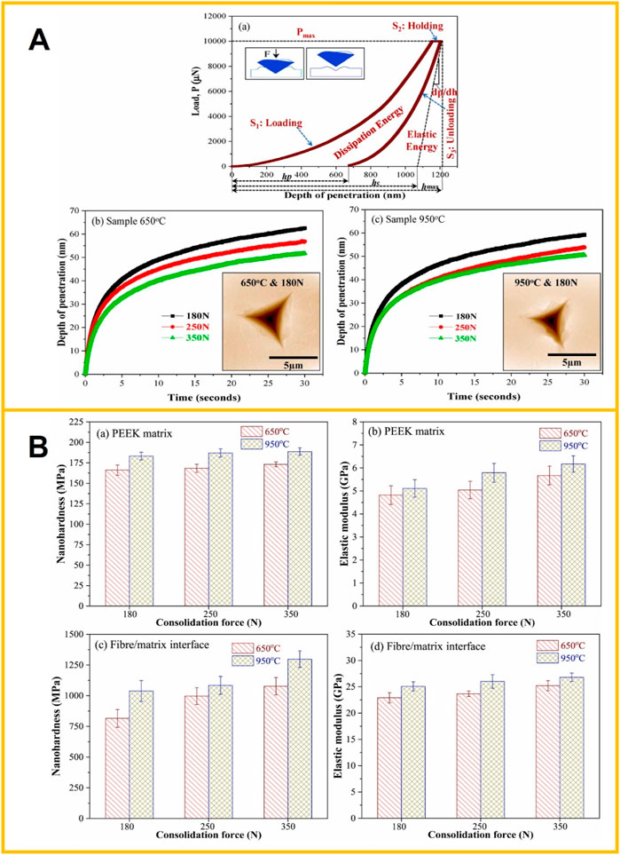
FIGURE 8. (A) (a) Load vs. displacement curve and creep performance of CF-PEEK composites in polymer matrix manufactured at different temperatures; (b) 650°C and (c) 950°C. Reprinted with permission from (Gain et al., 2022). Copyright 2022 Elsevier Ltd. (B) Nanohardness and elastic modulus as a function of consolidation force of CF-PEEK composites; (a, b) in polymer matrix and (c, d) fibre/matrix interface. Reprinted with permission from (Gain et al., 2022). Copyright 2022 Elsevier Ltd.
2.4.2.2 AFM peak force quantitative nanomechanical mode
In addition to characterizing the interface morphology and microstructure of CFRP, AFM also has peak force quantitative nanomechanical mode (PFQNM), which can directly qualitatively or quantitatively determine the micromechanical properties and physical properties (morphology, Young’s modulus, shape variable, viscosity, etc.) of various local regions in the interface at a high spatial resolution at the nanoscale (Dokukin and Sokolov, 2012). The technique uses extremely fine diamond tips to obtain a series of force curves based on the peak force tapping measurement mode. It then uses the Derjaguin-Muller-Toporov (DMT) model to perform fitting analysis calculations to obtain quantitative nanomechanical properties of the sample. It can obtain the quantitative nanomechanical properties and the morphology of CFRP.
AFM nanomechanical dynamic modulus imaging technology can quantitatively determine the modulus distribution of the interface microregion of CFRP in situ. It can clearly distinguish the fiber, polymer, and interface regions. The modulus of the interfacial phase varies between the polymer modulus and the fiber modulus, and the morphology and average thickness of the interface can be obtained by statistical analysis of the energy storage modulus imaging map (Liu et al., 2010). Niu et al. (2016) used the force modulation method of AFM to obtain an elastic modulus map of interphase in CF/PEEK. They discovered the interphase shrinkage under coupled UV and hydrothermal degradation. Qi et al. (2019) used PFQNM AFM imaging to determine the interphase thickness and properties of carbon fiber-reinforced epoxy matrix composites, and the surface topography, modulus, and adhesion were identified and distinguished. The interphase thickness quantitatively determined by the modulus map was consistent with the adhesion map.
Zheng et al. (2018) proposed an AFM technique to directly characterize the interfacial adhesion in carbon fiber/epoxy composite (Figure 9). The adhesion forces between epoxy-functionalized AFM tip and CFs with different surface chemistry and morphologies were characterized. The results indicated that the surface chemical properties of CF directly affected the interface adhesion. There was a good correlation between the measurement of adhesive force and the micro-bond test of a single fiber of carbon fiber/epoxy composite. This nanoscale AFM manipulation provided a new way to characterize the interfacial adhesion at the molecular level between CF and epoxy.
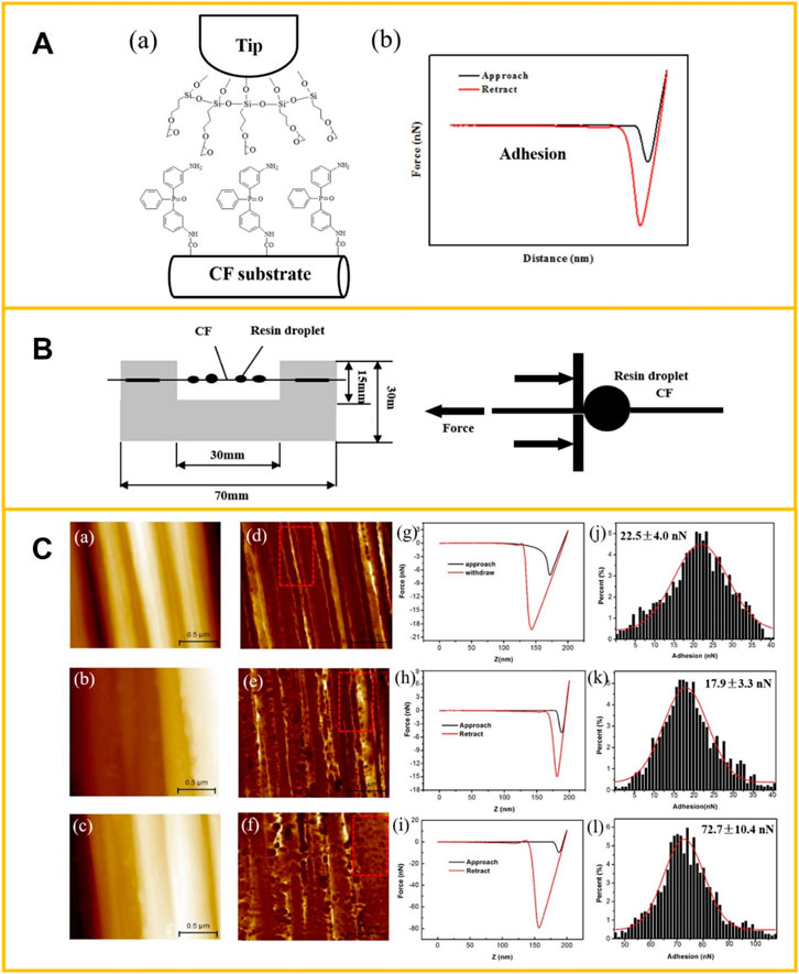
FIGURE 9. (A) Schematic diagram for the adhesion force measurement: (a) Epoxy functionalized tip and Bis (3-aminophenyl) phenyl phosphine oxide (BAPPO) modified CF; (b) typical force-distance curves during the adhesion force measurement. Reprinted with permission from (Zheng et al., 2018). Copyright 2018 Elsevier Ltd. (B) Schematic illustration of single fiber microbond test. Reprinted with permission from (Zheng et al., 2018). Copyright 2018 Elsevier Ltd. (C) Adhesion force measurement between the epoxy functionalized tip and CF samples. (a–c) AFM images of the as-received CF, de-sized CF and BAPPO-CF used in adhesion force measurement, respectively. (d–f) The corresponding adhesion maps of (a–c). (g–i) the representative force-displacement curves during the adhesion force measurement process. (j–l) Histograms of the measured adhesion forces between the epoxy functionalized tip and CFs. Reprinted with permission from (Zheng et al., 2018). Copyright 2018 Elsevier Ltd.
2.4.2.3 In situ SEM mechanical characterization
In situ SEM mechanical testing is very helpful in understanding the micromechanical properties, interfacial strength, and damage mechanism of CFRPs at the micron level, and helps to develop new composite materials. Totten et al. (2016) used a single-fiber test specimen to determine the tensile strength of the fiber-matrix interface by in situ SEM tensile test. The fiber was embedded perpendicularly to the loading axis through the thickness of the bond-shaped specimen. Adak et al. (2019) directly observed the micro delamination in GO-incorporated carbon fiber/epoxy composite via an in-situ SEM tensile test, and failure events were identified at the microscale.
Liu et al. (2018) developed an in situ SEM method to measure the interfacial strength of CF/epoxy composites in different surface states. FIB was used to prepare stretched sample lamella with half of the fiber and epoxy, and the tensile load was applied to the lamella by a nanomanipulator. The fiber was perpendicular to the tension axis, along the width of the specimen, and the deformation process was observed simultaneously using SEM images and IB images. This method enabled accurate strain measurement along the entire gage length, and the stretching and fracture behavior was clearly observed (Figure 10). And, combined with elemental analysis of EDX mapping in scanning transmission electron microscopy (STEM), the interaction between oxygen-containing groups and epoxy was found a key cause for impacting the interfacial strength.
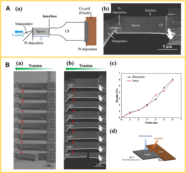
FIGURE 10. (A) (a) Sketch of a tensile specimen measuring the interfacial strength between the CF and epoxy matrix; (b) SEM image of final tensile specimen prepared by FIB-SEM. Adapted with permission of (Liu et al., 2018). Copyright 2018 Elsevier Ltd. (B) The stretching process of a raw CF/epoxy composite sample observed by SEM with two series: (a) Electron and (b) ion images; (c) strain-step curves during the stretching process, data extracted from two series of images; (d) sketch of the global sample position, about the stretching direction and the two beam sources. Adapted with permission of (Liu et al., 2018). Copyright 2018 Elsevier Ltd.
Ghaffari et al. (2021) developed an in situ SEM-based fiber push-out test to assess interface strength in CFRP. The fiber push-out response was measured by pushing individual fibers out of cave samples prepared by femtosecond laser machining, and compared with the response of benchmark specimens for high-modulus CFRP material systems (Figure 11). The fiber-matrix interface strength behavior was captured by SEM with a micromechanical load frame. Furthermore, finite element analysis was used to simulate the fiber push-out response before peak load and helped to understand the load-displacement curve shape determined by in situ micromechanical testing in SEM.
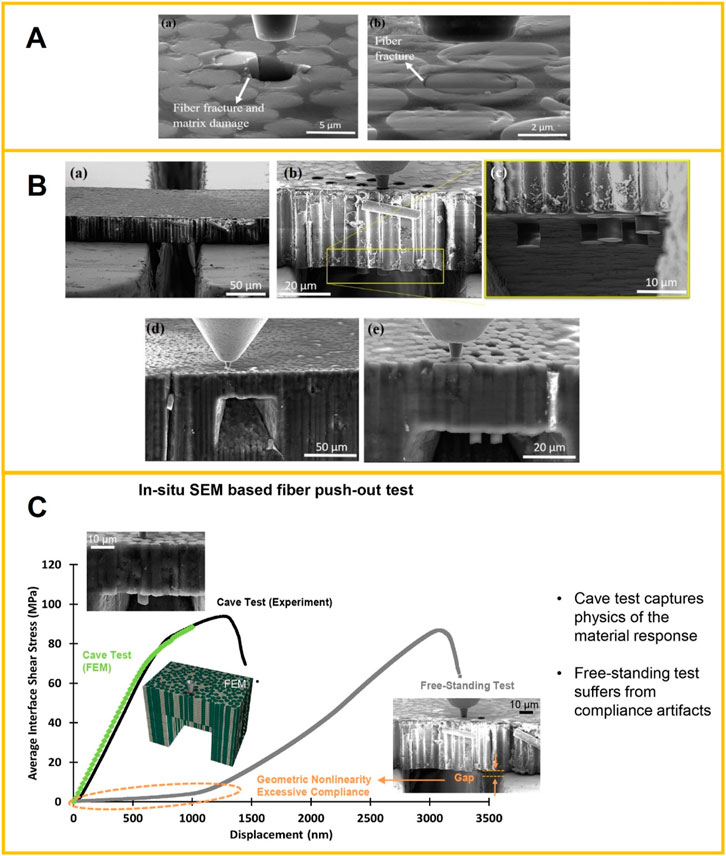
FIGURE 11. (A) Examples of SEM images from rejected push-out tests showing fiber fracture and matrix damage due to load eccentricity. Reprinted with permission from (Ghaffari et al., 2021). Copyright 2020 Elsevier Ltd. (B) Examples of typical SEM images of (a) a free-standing sample before fiber push-out testing and (b, c) after testing; (d) a cave sample before testing and (e) after testing. Reprinted with permission from (Ghaffari et al., 2021). Copyright 2020 Elsevier Ltd. (C) The schematic diagram of in-situ SEM-based fiber push-out test. Reprinted with permission from (Ghaffari et al., 2021). Copyright 2020 Elsevier Ltd.
2.4.2.4 In situ TEM mechanical characterization
In situ observation of local microstructural dynamics in fracture formation and propagation in CFRP is an advanced technique that can effectively evaluate cracks in CFRP. Combined with in situ mechanics in TEM, not only can the fracture kinetics of individual carbon fibers be observed (Beese et al., 2013), but also due to the atomic-level resolution of TEM, the atomic fracture process in CFRP can be clearly observed (Kizuka, 1998), which in turn provides experimental data support for related theories.
Egoshi et al. (2020) observed the microstructural dynamics in the separation of CFs from an adhesive resin matrix and the subsequent fiber extraction process using an in-situ deformation system in high-resolution TEM. The tensile force was applied using a micron-level precision mechanism and a picometer-level piezoelectric element (Figure 12A). TEM’s conventional and lattice imaging modes observed the in situ deformation process. During the fiber orientation tensile deformation, the maximum mechanical properties of CFRP, the maximum strength, were observed in situ at the CF/resin interface at atomic spatial resolution (Figure 12C). Ishikawa et al. (2020) directly observed the microscopic fracture process in CFRP during off-axis tensile deformation tests by in-situ TEM. This observation of the crack propagation and related structural variation quantitatively revealed the sizing treatment variation in the fracture features near the fiber/resin interfaces.
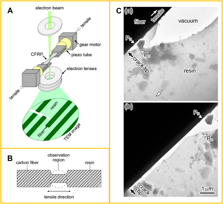
FIGURE 12. (A) Schematic of the in-situ TEM experimental system for the tensile deformation tests. Reprinted with permission from (Egoshi et al., 2020). Copyright 2020 Elsevier B.V. (B) Schematic of CFRP samples for in situ TEM of tensile deformation tests. Reprinted with permission from (Ishikawa et al., 2020). Copyright 2020 Elsevier B.V. (C) Snapshot TEM images of a CF’s side surface’s separation process in a sizing treatment (ST)-CFRP at on-axis tension. The upper left and the lower right sides are a CF and the resin matrix, respectively. The white arrows indicate the tension axis. The black arrow indicates the position of the crack tip. Pf1 and Pr1 in (a) and (b) represent the same CF and resin matrix positions, respectively. The deformation speed was 1.5 nm/s. Reprinted with permission from (Egoshi et al., 2020). Copyright 2020 Elsevier B.V.
2.4.2.5 In situ Raman spectroscopy mechanical characterization
The parameters that describe the properties of Raman spectroscopy mainly include the frequency shift, intensity (peak height or peak integration area), peak width, and polarization characteristics of Raman peaks. They reflect the material’s structure, properties, and environments from different angles. For example, all these parameters are related to the molecular structure and its aggregate state, so they can be utilized to analyze the microstructure of the composite interface. In contrast, the frequency shift is often related to the stress state of the specimen, and the relationship between them can be used to study the micromechanics of the composite interface.
The Raman spectral behavior of CFs under force deformation is the basis for Raman spectroscopy to study the micromechanics of CFRP interfaces. The three prominent Raman peaks of CF-D, G, and D* (or G′) are sensitive to fiber strain. Changes in peak position and width characterize Raman spectral behavior under tensile or compressive strain. The frequency of all three peaks shifts with strain, and there is a roughly linear relationship between the magnitude of the offset and the strain. This functional relationship can determine the strain distribution of CFs in composites.
Figure 13 shows the G′ Raman peak of a pitch-based high-modulus carbon fiber P100 under no strain and tension (0.6%) and compression (−0.2%) (Montes-Morán and Young, 2002). Under tensile strain, the peak position shifted in the direction of low-frequency shift, while under compressive strain, it responded in the opposite direction, and the peak position shifted in the direction of high-frequency shift. Peak D and peak G showed a similar phenomenon. Strain not only shifted the peak position but also changed the shape of the peak, such as the peak width.
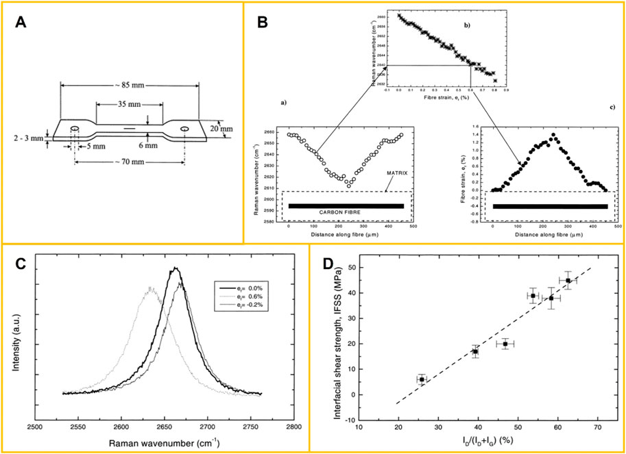
FIGURE 13. (A) Scheme and dimensions of the dumbbell single-fibre-epoxy specimens used to characterize the interface by use of Raman spectroscopy. Reprinted with permission from (Montes-Morán and Young, 2002). Copyright 2002 Elsevier Science B.V. (B) Basic steps describing the experimental procedure followed during Raman spectroscopy studies of interfaces in composites: (a) Raman spectra is taken along the fiber and the maximum of a Raman band is plotted vs. distance from fiber ends; (b) the maximum of the Raman band is transformed to strain using the appropriate calibration curve; (c) the strain distribution along the fiber is finally obtained. Reprinted with permission from (Montes-Morán and Young, 2002). Copyright 2002 Elsevier Science B.V. (C) The shift of the G’ (∼2,660 cm−1) Raman band peak on the application of tensile strain for the P100 fiber. Reprinted with permission from (Montes-Morán and Young, 2002). Copyright 2002 Elsevier Science B.V. (D) Variation of the interfacial shear strength, IFSS, of the different fiber-matrix systems with the parameter of structural order ID/(ID + IG) of the HM carbon fibers. Reprinted with permission from (Montes-Morán and Young, 2002). Copyright 2002 Elsevier Science B.V.
To determine the relationship between Raman peak shift and fiber strain in Raman spectroscopy, a force application device is required to cause stepwise strain on single fibers. For simple tensile strains, a simple micro-tensile device can be used. For the mechanical behavior of CFs and their composites in the compressed state, they can use cantilever bending devices, four-point bending devices, or three-point bending devices to apply tensile and compressive strain to single CFs.
Figure 14 showed the shift of G peak and G′ peak frequency shifts of CF as a function of fiber strain (measured from two fibers during stretching and compression) (Filiou and Galiotis, 1999). It can be seen that under both tensile strain and compressive strain, the change in the frequency of the two peaks before the fiber destroyed was approximately linear with the fiber strain. CF usually had different ways of breaking under tension and compression, broken by shear in the compressed state and brittle fracture in the tensile state. However, either way, once the fibers were destroyed, the frequency shift at the Raman peak position quickly returned to the frequency shift at zero strain.
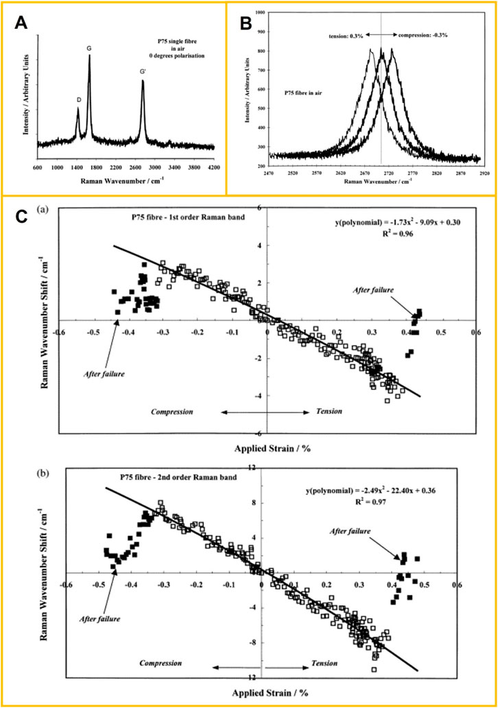
FIGURE 14. (A) Raman spectrum of the P75 fiber in air within the 600–4,200 cm−1 geometry of single ply and eight-ply unidirectional P75/PEEK coupons. Reprinted with permission from (Filiou and Galiotis, 1999). Copyright 1999 Elsevier Science Ltd. (B) Raman band shift for 0.3% applied strain in tension and compression. Reprinted with permission from (Filiou and Galiotis, 1999). Copyright 1999 Elsevier Science Ltd. (C) Raman wavenumber shift as a function of applied strain in tension and compression for (a) first-order Raman band at 1,580 cm−1 and (b) second-order Raman band at 2,705 cm−1. Reprinted with permission from (Filiou and Galiotis, 1999). Copyright 1999 Elsevier Science Ltd.
Ya and Pyrz, (2015) researched the reinforcement role of single-walled carbon nanotubes (SWCNT) in CFRP using Raman spectroscopy. SWCNT-epoxy specimen with a single CF on the top surface was loaded incrementally until sufficient strain levels caused the interfacial failure. By Raman spectroscopy, fiber strain profiles at each level of the applied strain were obtained, IFSS distribution at each applied matrix strain was derived, and the residual strains in the matrix near single CF were also mapped.
3 Future research directions and challenges
The interface is a highly complex structure formed under various environmental conditions, such as thermal, mechanical, and chemical conditions. Its properties are quite different from those of CF and polymer matrix. The interface has an important influence on the properties of CFRPs. Table 1 summarizes various interface microscopic characterization methods of CFRPs. How to microscopic characterize the micromorphology, microstructure, chemical composition and mechanical properties of the interface and how to improve and develop new interface characterization methods are still worthy of further research. The microscopic characterization methods of CFRPs are expected to make breakthroughs in the following aspects.
(1) The thickness of the interface layer of CFRPs ranges from nanometers to microns. Hence, it is necessary to improve further the microzone detection method of the interfacial microstructure, chemical composition and properties and improve the resolution of the method at nanometer and molecular scales.
(2) The microstructure and chemical composition of the same components located inside or at the interface are very different, which makes it challenging to quantitatively research the microstructure, composition and properties of the interface, and it is necessary to improve detection methods further.
(3) The characterization analysis should reflect the interface information as honestly as possible, which requires minimizing the damage during sample preparation and not destroying the original structure and properties of the interface. In addition, various factors should be integrated into the analysis of experimental results to remove the illusion.
(4) The current interfacial mechanic’s analysis lacks support for the experimental data at the nanoscale and molecular scales, and an accurate quantitative basis is still needed.
(5) How to link the interface micro properties such as interface chemical reaction, interface stress and interface microstructure with the macroscopic properties of CFRP? Although people have progressed through the mesoscopic mechanical theory of interfaces in recent years, many problems remain to be solved.
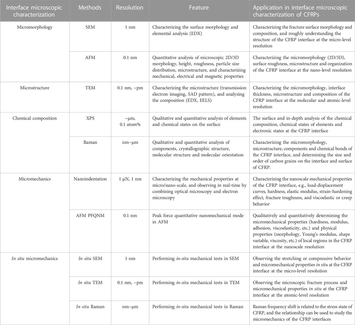
TABLE 1. Interface microscopic characterization methods of CFRPs.
4 Summary
In summary, interface theory has been widely accepted by the scientific community and widely used to guide practical work; with the help of advanced instrument technology, people have established appropriate interface microscopic characterization and analysis methods, and through the combination of a variety of technologies, from multiple angles to make us a more precise understanding of the interface of CFRPs. We should continue to conduct detailed and accurate research on the micromorphology, microstructure, chemical composition and mechanical properties of the microscopic interface to better explain the impact mechanism of the interface on the performance, guide and optimize interface design of carbon fiber and polymer, and make CFRPs play its more significant advantages.
Author contributions
All authors listed have made a substantial, direct, and intellectual contribution to the work and approved it for publication.
Conflict of interest
The authors declare that the research was conducted in the absence of any commercial or financial relationships that could be construed as a potential conflict of interest.
Publisher’s note
All claims expressed in this article are solely those of the authors and do not necessarily represent those of their affiliated organizations, or those of the publisher, the editors and the reviewers. Any product that may be evaluated in this article, or claim that may be made by its manufacturer, is not guaranteed or endorsed by the publisher.
References
Adak, N., Chhetri, S., Sabarad, S., Roy, H., Murmu, N., Samanta, P., et al. (2019). Direct observation of micro delamination in graphene oxide incorporated carbon fiber/epoxy composite via in-situ tensile test. Compos. Sci. Technol. 177, 57–65. doi:10.1016/j.compscitech.2019.04.006
Aldousiri, B., Dhakal, H., Onuh, S., Zhang, Z., and Bennett, N. (2011). Nanoindentation behaviour of layered silicate filled spent polyamide-12 nanocomposites. Polym. Test. 30 (6), 688–692. doi:10.1016/j.polymertesting.2011.05.008
Beese, A. M., Papkov, D., Li, S., Dzenis, Y., and Espinosa, D. (2013). In situ transmission electron microscope tensile testing reveals structure-property relationships in carbon nanofibers. Carbon 60, 246–253. doi:10.1016/j.carbon.2013.04.018
Butt, H. J., Cappella, B., and Kappl, M. (2005). Force measurements with the atomic force microscope: Technique, interpretation and applications. Surf. Sci. Rep. 59 (1-6), 1–152. doi:10.1016/j.surfrep.2005.08.003
Charan, V., Vardhan, A., Raj, S., Rao, G., Rao, G. V., and Hussaini, S. M. (2019). Experimental characterization of CFRP by NOL ring test. Mater. Today Proc. 18 (7), 2868–2874. doi:10.1016/j.matpr.2019.07.154
Chen, L., Li, Z., Wu, G., Wang, Y., Wang, T., Ma, Y., et al. (2018). Ultra-strong polyethyleneimine-graphene oxide nanocomposite film via synergistic interactions and its use for humidity sensing. Compos. Part A Appl. Sci. Manuf. 115, 341–347. doi:10.1016/j.compositesa.2018.10.011
Dang, Z. M., Yuan, J. K., Zha, J. W., Zhou, T., Li, S. T., and Hu, G. H. (2012). Fundamentals, processes and applications of high-permittivity polymer-matrix composites. Prog. Mater. Sci. 57 (4), 660–723. doi:10.1016/j.pmatsci.2011.08.001
Dawood, M., El-Tahan, M. W., and Zheng, B. (2015). Bond behavior of superelastic shape memory alloys to carbon fiber reinforced polymer composites. Compos. Part B Eng. 77, 238–247. doi:10.1016/j.compositesb.2015.03.043
Dhieb, H., Buijnsters, J. G., Elleuch, K., and Celis, J. P. (2016). Effect of relative humidity and full immersion in water on friction, wear and debonding of unidirectional carbon fiber reinforced epoxy under reciprocating sliding. Compos. Part B Eng. 88, 240–252. doi:10.1016/j.compositesb.2015.11.011
Dokukin, M. E., and Sokolov, I. (2012). Quantitative mapping of the elastic modulus of soft materials with HarmoniX and PeakForce QNM AFM modes. Langmuir 28 (46), 16060–16071. doi:10.1021/la302706b
Downing, T. D., Kumar, R., Cross, W. M., Kjerengtroen, L., and Kellar, J. J. (2000). Determining the interphase thickness and properties in polymer matrix composites using phase imaging atomic force microscopy and nanoindentation. J. Adhesion Sci. Technol. 14, 1801–1812. doi:10.1163/156856100743248
Egoshi, T., Ishikawa, T., Tezura, M., and Kizuka, T. (2020). Transmission electron microscopy of unidirectional carbon fiber reinforced plastics at on-Axis tension. Materialia 14, 100907. doi:10.1016/j.mtla.2020.100907
Fei, J., Luo, D., Huang, J., Zhang, C., Duan, X., and Zhang, L. (2018). Growth of aligned ZnO nanorods on carbon fabric and its composite for superior mechanical and tribological performance. Surf. Coatings Technol. 344, 433–440. doi:10.1016/j.surfcoat.2018.03.056
Ferencz, R., Sanchez, J., Blümich, B., and Herrmann, W. (2012). AFM nanoindentation to determine Young's modulus for different EPDM elastomers. Polym. Test. 31 (3), 425–432. doi:10.1016/j.polymertesting.2012.01.003
Filiou, C., and Galiotis, C. (1999). In situ monitoring of the fibre strain distribution in carbon-fibre thermoplastic composites1. Application of a tensile stress field. Compos. Sci. Technol. 59 (14), 2149–2161. doi:10.1016/s0266-3538(99)00072-x
Fischer-Cripps, A. C. (2009). Handbook of nanoindentation. Forestville, NSW, Australia: Fischer-Cripps Laboratories Pty Ltd. Part 1.
Florek, P., Król, M., Jeleń, P., and Mozgawa, W. (2021). Carbon fiber reinforced polymer composites doped with graphene oxide in light of spectroscopic studies. Materials 14 (8), 1835. doi:10.3390/ma14081835
Fu, X., Yi, D., Tan, C., and Wang, B. (2020). Micromechanics analysis of carbon fiber/epoxy microdroplet composite under UV light irradiation by micro-Raman spectroscopy. Polym. Compos. 41 (6), 2154–2168. doi:10.1002/pc.25528
Gain, A. K., Oromiehie, B., and Prusty, B. G. (2022). Nanomechanical characterisation of CF-PEEK composites manufactured using automated fibre placement (AFP). Compos. Commun. 31, 101109. doi:10.1016/j.coco.2022.101109
Gan, X. (2009). Effect of interface structure on mechanical properties of advanced composite materials. Int. J. Mol. Sci. 10 (12), 5115–5134. doi:10.3390/ijms10125115
George, J., Sreekala, M. S., and Thomas, S. (2001). A review on interface modification and characterization of natural fiber reinforced plastic composites. Polym. Eng. Sci. 41 (9), 1471–1485. doi:10.1002/pen.10846
Ghaffari, S., Seon, S., and Makeev, A. (2021). In-situ SEM based method for assessing fiber-matrix interface shear strength in CFRPs. Mater. Des. 197, 109242. doi:10.1016/j.matdes.2020.109242
Gong, X. J., Arthur, J. A., and Penn, L. S. (2001). Strain rate effect in the single-fiber-fragmentation test. Polym. Compos. 22 (3), 349–360. doi:10.1002/pc.10543
Guigon, M., and Klinklin, E. (1994). The interface and interphase in carbon fibre-reinforced composites. Composites 25 (7), 534–539. doi:10.1016/0010-4361(94)90181-3
He, D., Fan, B., Zhao, H., Lu, X., Yang, M., Liu, Y., et al. (2017). Design of electrically conductive structural composites by modulating aligned CVD-grown carbon nanotube length on glass fibers. ACS Appl. Mat. Interfaces 9 (3), 2948–2958. doi:10.1021/acsami.6b13397
He, H., Xu, P., Zhang, Y., Liu, K., and Yang, X. (2020). Phthalocyanine nanowires@GO/carbon fiber composites with enhanced interfacial properties and electromagnetic interference shielding performance. Chem. Eng. J. 388, 124255. doi:10.1016/j.cej.2020.124255
Ishikawa, T., Tezura, M., and Kizuka, T. (2020). Direct observation of microstructural fracture dynamics in carbon fiber reinforced plastics via in situ transmission electron microscopy. Compos. Sci. Technol. 198, 108264. doi:10.1016/j.compscitech.2020.108264
Ismail, I. K., and Vangsness, M. D. (1988). On the improvement of carbon fiber/matrix adhesion. Carbon 26 (5), 749–751. doi:10.1016/0008-6223(88)90081-4
Jain, V., Bisht, A., Jaiswal, S., Dasgupta, K., and Lahiri, D. (2021). Assessment of interfacial interaction in graphene nanoplatelets and carbon fiber-reinforced epoxy matrix multiscale composites and its effect on mechanical behavior. J. Materi Eng Perform 30, 8913–8925. doi:10.1007/s11665-021-06115-2
Jee, A. Y., and Lee, M. (2010). Comparative analysis on the nanoindentation of polymers using atomic force microscopy. Polym. Test. 29 (1), 95–99. doi:10.1016/j.polymertesting.2009.09.009
Jin, F. L., Lee, S. Y., and Park, S. J. (2013). Polymer matrices for carbon fiber-reinforced polymer composites. Carbon Lett. 14 (2), 76–88. doi:10.5714/cl.2013.14.2.076
Jin, F. L., and Park, S. J. (2015). Preparation and characterization of carbon fiber-reinforced thermosetting composites: A review. Carbon Lett. 16 (2), 67–77. doi:10.5714/cl.2015.16.2.067
Jones, A. R., Cintora, A., White, R., and Sottos, N. R. (2014). Autonomic healing of carbon fiber/epoxy interfaces. ACS Appl. Mat. Interfaces 6 (9), 6033–6039. doi:10.1021/am500536t
Kim, B. W., and Nairn, J. A. (2002). Observations of fiber fracture and interfacial debonding phenomena using the fragmentation test in single fiber composites. J. Compos. Mater. 36 (15), 1825–1858. doi:10.1177/0021998302036015243
Kim, M., Sung, D., Kong, K., Kim, N., Kim, B. J., Park, H. W., et al. (2016). Characterization of resistive heating and thermoelectric behavior of discontinuous carbon fiber-epoxy composites. Compos. Part B Eng. 90, 37–44. doi:10.1016/j.compositesb.2015.11.037
Kizuka, T. (1998). Atomistic visualization of deformation in gold. Phys. Rev. B 57, 11158–11163. doi:10.1103/physrevb.57.11158
Krishnan, P. (2017). A novel microbond bundle pullout technique to evaluate the interfacial properties of fibre-reinforced plastic composites. Bull. Mater Sci. 40 (4), 737–744. doi:10.1007/s12034-017-1415-z
Li, N., Zong, L., Wu, Z., Liu, C., Wang, X., Bao, F., et al. (2017). Amino-terminated nitrogen-rich layer to improve the interlaminar shear strength between carbon fiber and a thermoplastic matrix. Compos. Part A Appl. Sci. Manuf. 101, 490–499. doi:10.1016/j.compositesa.2017.06.023
Li, Y., Li, M., Gu, Y., Zhang, Z., and Guan, P. (2012). Investigation of the nanoscale mechanical properties of carbon fiber/epoxy resin interphase. I. Analysis of fiber-stiffening effect during the nanoindentation process based on numerical simulation. Polym. Compos 33 (8), 1387–1394. doi:10.1002/pc.22265
Liang, C., and Hutchinson, J. W. (1993). Mechanics of the fiber pushout test. Mech. Mater. 14 (3), 207–221. doi:10.1016/0167-6636(93)90067-2
Liang, Y., Tuo, Z., Zhao, Q., Lin, L., Lin, Z., Han, Z., et al. (2021). Study on preparation and mechanical properties of bionic carbon fiber reinforced epoxy resin composite with eagle feather structure. Mat. Res. Express 8 (6), 065301. doi:10.1088/2053-1591/ac0368
Liao, Q., Huang, J., Zhu, T., Xiong, C., and Fang, J. (2010). A hybrid model to determine mechanical properties of soft polymers by nanoindentation. Mech. Mater. 42 (12), 1043–1047. doi:10.1016/j.mechmat.2010.09.005
Lin, G. (2022). CINTE21. 2021 global carbon fiber composites market report. Text. Sci. Res. 2022 (Z1), 46–66.
Lin, G., Geubelle, P. H., and Sottos, N. R. (2001). Simulation of fiber debonding with friction in a model composite pushout test. Int. J. Solids Struct. 38 (46-47), 8547–8562. doi:10.1016/s0020-7683(01)00085-3
Liu, L., Jia, C., He, J., Zhao, F., Fan, D., Xing, L., et al. (2015). Interfacial characterization, control and modification of carbon fiber reinforced polymer composites. Compos. Sci. Technol. 121, 56–72. doi:10.1016/j.compscitech.2015.08.002
Liu, Q., Gu, Y., Li, M., Liu, N., and Zhang, Z. (2010). Characterization on the interfacial structure of carbon fiber composites using dynamic modulus imaging methods. Compos. Mater. Innovation Sustain. 2010, 788–793.
Liu, Y., He, D., Hamon, A. L., Fan, B., Haghi-Ashtiani, P., Reiss, T., et al. (2018). Comparison of different surface treatments of carbon fibers used as reinforcements in epoxy composites: Interfacial strength measurements by in-situ scanning electron microscope tensile tests. Compos. Sci. Technol. 167, 331–338. doi:10.1016/j.compscitech.2018.08.018
Lu, J. H., and Youngblood, J. P. (2015). Adhesive bonding of carbon fiber reinforced composite using UV-curing epoxy resin. Compos. Part B Eng. 82, 221–225. doi:10.1016/j.compositesb.2015.08.022
Luo, W., Liu, L., Li, Y., Zhou, S., Zou, H., and Liang, M. (2016). Enhanced mechanical and tribological properties in polyphenylene sulfide/polytetrafluoroethylene composites reinforced by short carbon fiber. Compos. Part B Eng. 91, 579–588. doi:10.1016/j.compositesb.2016.01.036
Mei, J., Liu, J., and Huang, W. (2022). Three-point bending behaviors of the foam-filled CFRP X-core sandwich panel: Experimental investigation and analytical modelling. Compos. Struct. 284, 115206. doi:10.1016/j.compstruct.2022.115206
Molazemhosseini, A., Tourani, H., Naimi-Jamal, M. R., and Khavandi, A. (2013). Nanoindentation and nanoscratching responses of PEEK based hybrid composites reinforced with short carbon fibers and nano-silica. Polym. Test. 32 (3), 525–534. doi:10.1016/j.polymertesting.2013.02.001
Montes-Morán, M. A., and Young, R. J. (2002). Raman spectroscopy study of high-modulus carbon fibres: Effect of plasma-treatment on the interfacial properties of single-fibre-epoxy composites. Carbon 40, 857–875. doi:10.1016/s0008-6223(01)00207-x
Nabil, M. (2016). Chowdhury, wing kong chiu, john Wang, Paul chang. Experimental and finite element studies of bolted, bonded and hybrid step lap joints of thick carbon fibre/epoxy panels used in aircraft structures. Compos. Part B Eng. 100, 68–77.
Nakayama, Y., Soeda, F., and Ishitani, A. (1990). XPS study of the carbon fiber matrix interface. Carbon 28 (1), 21–26. doi:10.1016/0008-6223(90)90088-g
Nishikawa, M., Okabe, T., Hemmi, K., and Takeda, N. (2008). Micromechanical modeling of the microbond test to quantify the interfacial properties of fiber-reinforced composites. Int. J. Solids Struct. 45 (14-15), 4098–4113. doi:10.1016/j.ijsolstr.2008.02.021
Niu, Y. F., Yang, Y., Gao, S., and Yao, J. W. (2016). Mechanical mapping of the interphase in carbon fiber reinforced poly(ether-ether-ketone) composites using peak force atomic force microscopy: Interphase shrinkage under coupled ultraviolet and hydro-thermal exposure. Polym. Test. 55, 257–260. doi:10.1016/j.polymertesting.2016.09.008
Park, S. J., and Jang, Y. S. (2003). X-ray diffraction and X-ray photoelectron spectroscopy studies of Ni-P deposited onto carbon fiber surfaces: Impact properties of A carbon-fiber-reinforced matrix. J. Colloid Interface Sci. 263, 170–176. doi:10.1016/s0021-9797(03)00290-x
Park, S. J., Kim, M. H., Lee, J. R., and Choi, S. (2000). Effect of fiber-polymer interactions on fracture toughness behavior of carbon fiber-reinforced epoxy matrix composites. J. Colloid Interface Sci. 228 (2), 287–291. doi:10.1006/jcis.2000.6953
Park, S. J., Lee, S. Y., and Jin, F. L. (2015). “Surface modification of carbon nanotubes for high-performance polymer composites,” in Handbook of polymer nanocomposites. Processing, performance and application (Berlin, Heidelberg: Springer-Verlag), 13–59. doi:10.1007/978-3-642-45229-1_34
Park, S. J., and Seo, M. K. (2012). Carbon fiber-reinforced polymer composites: Preparation, properties, and applications. Polym. Compos. 1, 135–183. doi:10.1002/9783527645213.ch5
Qi, Y., Jiang, D., Ju, J., Zhang, J., and Cui, X. (2019). Determining the interphase thickness and properties in carbon fiber reinforced fast and conventional curing epoxy matrix composites using peak force atomic force microscopy. Compos. Sci. Technol. 184, 107877. doi:10.1016/j.compscitech.2019.107877
Ryu, S. K., Park, B. J., and Park, S. J. (1999). XPS analysis of carbon fiber surfaces-anodized and interfacial effects in fiber-epoxy composites. J. Colloid Interface Sci. 215, 167–169. doi:10.1006/jcis.1999.6240
Schultz, J., and Lavielle, L. (1989). Interfacial properties of carbon fiber-epoxy matrix composites. Inverse Gas. Chromatogr. 1989, 185–202. doi:10.1021/bk-1989-0391.ch014
Schultz, J., Lavielle, L., and Martin, C. (1987). The role of the interface in carbon fibre-epoxy composites. J. Adhesion 23 (1), 45–60. doi:10.1080/00218468708080469
Serri, M., Mannini, M., Poggini, L., Vélez-Fort, E., Cortigiani, B., Sainctavit, P., et al. (2017). Low-temperature magnetic force microscopy on single molecule magnet-based microarrays. Nano Lett. 17 (3), 1899–1905. doi:10.1021/acs.nanolett.6b05208
Sha, J. J., Dai, J. X., Li, J., Wei, Z. Q., Hausherr, J-M., and Krenkel, W. (2013). Measurement and analysis of fiber-matrix interface strength of carbon fiber-reinforced phenolic resin matrix composites. J. Compos. Mater. 48 (11), 1303–1311. doi:10.1177/0021998313485264
Shen, L., Tjiu, W. C., and Liu, T. (2005). Nanoindentation and morphological studies on injection-molded nylon-6 nanocomposites. Polymer 46 (25), 11969–11977. doi:10.1016/j.polymer.2005.10.006
Shen, L., Wang, L., Liu, T., and He, C. (2006). Nanoindentation and morphological studies of epoxy nanocomposites. Macromol. Mat. Eng. 291 (11), 1358–1366. doi:10.1002/mame.200600184
Sokolov, I., Ong, Q. K., Shodiev, H., Chechik, N., James, D., and Oliver, M. (2006). AFM study of forces between silica, silicon nitride and polyurethane pads. J. Colloid Interface Sci. 300 (2), 475–481. doi:10.1016/j.jcis.2006.04.023
Stojcevski, S., Hilditch, T., and Henderson, C. (2018). A modern account of Iosipescu testing. Compos. Part A Appl. Sci. Manuf. 107, 545–554. doi:10.1016/j.compositesa.2018.02.011
Thomson, D., Quino, G., Cui, H., Pellegrino, A., Erice, B., and Petrinic, N. (2020). Strain-rate and off-Axis loading effects on the fibre compression strength of CFRP laminates: Experiments and constitutive modelling. Compos. Sci. Technol. 195, 108210. doi:10.1016/j.compscitech.2020.108210
Tomita, A., and Chiao, Y. (1986). Observation of berry's topological phase by use of an optical fiber. Phys. Rev. Lett. 57 (8), 937–940. doi:10.1103/physrevlett.57.937
Totry, E., Molina-Aldareguía, M., González, C., Carlos, G., and Llorca, J. (2010). Effect of fiber, matrix and interface properties on the in-plane shear deformation of carbon-fiber reinforced composites. Compos. Sci. Technol. 70 (6), 970–980. doi:10.1016/j.compscitech.2010.02.014
Totten, K. R., Kutub, B., and Carlsson, L. A., (2016). In situ determination of the fiber-matrix interface tensile strength. J. Compos. Mater. 50 (5), 589–599. doi:10.1177/0021998315579926
Variola, F. (2015). Atomic force microscopy in biomaterials surface science. Phys. Chem. Chem. Phys. 17 (5), 2950–2959. doi:10.1039/c4cp04427d
Vijaya Kumar, K., Safiulla, M., and Khaleel Ahmed, A. N. (2017). Experimental characterization of ILSS of CFRP laminates. Int. J. Eng. Res. Technol. 6 (1), 274–277.
Viswanathan, H., Wang, Y. Q., Audi, A. A., Allen, P. J., Sherwood, M., and Sherwood, A. (2001). X-Ray photoelectron spectroscopic studies of carbon fiber surfaces. 24. Interfacial interactions between polyimide resin and electrochemically oxidized PAN-based carbon fibers. Chem. Mat. 13 (5), 1647–1655. doi:10.1021/cm000930h
Wang, F. S., Ji, Y. Y., Yu, X. S., Chen, H., and Yue, Z. F. (2016). Ablation damage assessment of aircraft carbon fiber/epoxy composite and its protection structures suffered from lightning strike. Compos. Struct. 145, 226–241. doi:10.1016/j.compstruct.2016.03.005
Wang, Y., and Hahn, H. (2007). AFM characterization of the interfacial properties of carbon fiber reinforced polymer composites subjected to hygrothermal treatments. Compos. Sci. Technol. 67 (1), 92–101. doi:10.1016/j.compscitech.2006.03.030
Wichita State University NIAR (2012). Composite materials handbook-17g: Polymer matrix composites. Wichita, KS, USA: SAE International Press.
Wu, Q., Li, M., Gu, Y., Li, Y., and Zhang, Z. (2014). Nano-analysis on the structure and chemical composition of the interphase region in carbon fiber composite. Compos. Part A Appl. Sci. Manuf. 56, 143–149. doi:10.1016/j.compositesa.2013.10.003
Wu, Q., Li, M., Gu, Y., Wang, S., and Zhang, Z. (2015). Imaging the interphase of carbon fiber composites using transmission electron microscopy: Preparations by focused ion beam, ion beam etching, and ultramicrotomy. Chin. J. Aeronautics 28 (5), 1529–1538. doi:10.1016/j.cja.2015.05.005
Wu, Y., Wang, L. X., Xu, H., Wang, S., Peng, L., Zheng, Z., et al. (2021). Preparation of silver-plated carbon nanotubes/carbon fiber hybrid fibers by combining freeze-drying deposition with A sizing process to enhance the mechanical properties of carbon fiber composites. Compos. Part A Appl. Sci. Manuf. 146, 106421. doi:10.1016/j.compositesa.2021.106421
Xia, D., Zhang, S., Hjortdal, J. Ø., Li, Q., Thomsen, K., Chevallier, J., et al. (2014). Hydrated human corneal stroma revealed by quantitative dynamic atomic force microscopy at nanoscale. ACS Nano 8 (7), 6873–6882. doi:10.1021/nn5015837
Xu, B., Wei, M. Y., Wu, X. Y., Fu, L. Y., Luo, F., and Lei, J. G. (2021). Fabrication of micro-groove on the surface of CFRP to enhance the connection strength of composite part. Polymers 13 (22), 4039. doi:10.3390/polym13224039
Xu, H., Zhang, X., Liu, D., Yan, C., Chen, X., Hui, D., et al. (2016). Cyclomatrix-type polyphosphazene coating: Improving interfacial property of carbon fiber/epoxy composites and preserving fiber tensile strength. Compos. Part B Eng. 93, 244–251. doi:10.1016/j.compositesb.2016.03.033
Ya, Y., and Pyrz, R. (2015). Reinforcement role of carbon nanotubes: Interfacial properties of carbon fibre - epoxy nanocomposite. Polym. Polym. Compos. 23 (4), 213–222. doi:10.1177/096739111502300402
Yamamoto, T., Uematsu, K., Irisawa, T., and Tanabe, Y. (2016). Controlling of the interfacial shear strength between thermoplastic resin and carbon fiber by adsorbing polymer particles on carbon fiber using electrophoresis. Compos. Part A Appl. Sci. Manuf. 88, 75–78. doi:10.1016/j.compositesa.2016.05.021
Yang, C., Zhu, D., Yang, F., Liu, Q., Sun, C., Lei, K., et al. (2020). Quantitative analysis based on atomic force microscopy characterization of interfacial properties between carbon fibers and epoxy resin subjected to hygrothermal and thermal treatments. Compos. Sci. Technol. 198, 108278. doi:10.1016/j.compscitech.2020.108278
Yavas, D., Zhang, Z., Liu, Q., and Wu, D. (2021). Interlaminar shear behavior of continuous and short carbon fiber reinforced polymer composites fabricated by additive manufacturing. Compos. Part B Eng. 204, 108460. doi:10.1016/j.compositesb.2020.108460
Yilmaz, Y. I. (2002). Analyzing single fiber fragmentation test data by using stress transfer model. J. Compos. Mater. 36 (5), 537–551. doi:10.1177/0021998302036005465
Zhandarov, S., and Mäder, E. (2005). Peak force as function of the embedded length in pull-out and microbond tests: Effect of specimen geometry. J. Adhesion Sci. Technol. 19 (10), 817–855. doi:10.1163/1568561054929937
Zhang, X., Sun, T., Lei, Y., Liang, M., and Zou, H. (2021). Synergistically optimizing interlaminar behavior of CFRP composites by simultaneously applying amino-rich graphene oxide to carbon fiber and epoxy matrix. Compos. Part A Appl. Sci. Manuf. 145, 106372. doi:10.1016/j.compositesa.2021.106372
Zhang, Y., Wang, H., Lu, H., Li, S., and Zhang, Y. (2021). Electronic fibers and textiles: Recent progress and perspective. iScience 24 (7), 102716. doi:10.1016/j.isci.2021.102716
Zhao, Z., Teng, K., Li, N., Li, X., Xu, Z., Chen, L., et al. (2017). Mechanical, thermal and interfacial performances of carbon fiber reinforced composites flavored by carbon nanotube in matrix/interface. Compos. Struct. 159, 761–772. doi:10.1016/j.compstruct.2016.10.022
Zheng, N., He, J., Gao, J., Huang, Y., Besenbacher, F., and Dong, M. (2018). Adhesion force measured by atomic force microscopy for direct carbon fiber-epoxy interfacial characterization. Mater. Des. 145, 218–225. doi:10.1016/j.matdes.2018.02.060
Zheng, N., He, J., Zhao, D., Huang, Y., Gao, J., and Mai, Y. W. (2016). Improvement of atomic oxygen erosion resistance of carbon fiber and carbon fiber/epoxy composite interface with a silane coupling agent. Mater. Des. 109, 171–178. doi:10.1016/j.matdes.2016.07.004
Zheng, Q. (2009). PAN-Based carbon fiber reinforced composite materials production process and application. Chem. Fiber Text. Technol. 3, 26–31.
Keywords: carbon fiber reinforced polymer composites (CFRPs), composites, interface, microscopic characterization, micromorphology, microstructure, chemical composition, mechanical property
Citation: Liu L, Du M and Liu F (2023) Recent advances in interface microscopic characterization of carbon fiber-reinforced polymer composites. Front. Mater. 10:1124338. doi: 10.3389/fmats.2023.1124338
Received: 15 December 2022; Accepted: 30 January 2023;
Published: 09 February 2023.
Edited by:
Xiangdong Liu, Changchun Institute of Applied Chemistry (CAS), ChinaReviewed by:
Qilu Zhang, Xi’an Jiaotong University, ChinaChuanli Qin, Heilongjiang University, China
Copyright © 2023 Liu, Du and Liu. This is an open-access article distributed under the terms of the Creative Commons Attribution License (CC BY). The use, distribution or reproduction in other forums is permitted, provided the original author(s) and the copyright owner(s) are credited and that the original publication in this journal is cited, in accordance with accepted academic practice. No use, distribution or reproduction is permitted which does not comply with these terms.
*Correspondence: Feng Liu, bGl1ZmVuZ0Bud3B1LmVkdS5jbg==
†These authors have contributed equally to this work and share first authorship