 Xuemeng Wang
 Lan Xiong1
 Zhanlong Zhang
 Yihua Dan
- 1State Key Laboratory of Power Transmission Equipment & System Security and New Technology, Chongqing University, Chongqing, China
- 2Department of Electronic Engineering, Tsinghua University, Beijing, China
The grounding electrodes are buried in a harsh soil environment, which will cause corrosion. Corroded grounding electrodes directly affect the safe and stable operation of the power system. Therefore, it is particularly important to detect the corrosion degree of the grounding electrodes accurately. The existing methods have the following problems: 1) Power-frequency grounding resistance is used as a single criterion, and lack of considering the impulse characteristics, which is difficult to accurately judge the corrosion degree and could cause a potential safety hazard. 2) Lacking considering the environmental PH value, water content, salt content, and other factors of the buried soil, which is easy to lead to misjudgment of corrosion degree. To solve the problems, this paper studies a comprehensive evaluation of corroded grounding electrodes considering impulse characteristics. Based on thermal stability, impulse characteristics, and power frequency characteristics, the minimum safety diameter of grounding electrodes and the factors that affect the corrosion of the soil environment are studied. According to the relationship between each evaluation factors and corrosivity, the membership is calculated and combined with the comprehensive weight determined by the sum of the squares of deviation. The fuzzy evaluation method is adopted to obtain the corrosive evaluation matrix Y, and the corrosive index C is proposed to quantify the corrosive strength. Combined with the minimum safety diameter, the residual life range of the grounding electrodes is predicted and the corrosion degree is divided. Finally, a comprehensive corrosion evaluation algorithm considering impulse characteristics is proposed. The results show that this method not only considers the soil environmental factors but also considers the grounding characteristics of the grounding electrodes, especially the impulse characteristics. This method is more comprehensive than other evaluation methods which only consider the soil environment and can realize trenchless corrosion detection of grounding electrodes. Therefore, the contribution of this work is of great significance to the operation and maintenance of tower grounding electrodes.
1 Introduction
The tower grounding electrodes are composed of grounding electrodes and grounding lead conductors, which is the basis for establishing effective lightning protection design. The tower grounding electrodes are mainly used to provide a discharging channel for lightning current and fault current (Yamamoto et al., 2015). The grounding electrodes are prone to corrosion due to the influence of acid, alkali, and salt content in the soil (Lu et al., 2022), which will cause the grounding electrodes to become thinner and the grounding resistance to increase. In the corrosion situation, the grounding electrodes’ thermal stability, power-frequency characteristics, and impulse characteristics of the grounding electrodes are difficult to meet the standards. Therefore, it is significant to evaluate the corrosion status of grounding electrodes for the operation and maintenance of transmission line towers.
The traditional grounding electrode corrosion detection method used industry-standard guidelines (IEEE, 2012; Jiang and Li., 2021) to measure the power-frequency grounding resistance. When the power-frequency grounding resistance is larger than the standard value, the excavation inspection of the grounding electrodes is carried out. However, the impulse characteristics of the corrosion grounding electrodes are not considered, resulting in incomplete and inaccurate evaluation, which hinders the normal operation of the power system. Wasim and Djukic conducted various corrosion tests on carbon steel in different critical and representative environments, and obtained corrosion rates under different backgrounds (Wasim and Djukic, 2020); Pankaj K. Seen et al. studied corrosion data from 44 soils tested by the United States National Bureau of Standards for 12 years and obtained fitting formula of corrosion rate of steel in soil (Wang and He, 2010). But the corrosion evaluation is highly dependent on the data. With the popularity of machine operation and multiple intelligent algorithms for the evaluation of corrosion rate prediction is also widely applied. Du and Li (2013) proposed a method combining structural clustering analysis and support vector regression; Liu (2019) proposed a method for predicting the corrosion rate of a grounding network based on an artificial bee colony algorithm to optimize a support vector machine, and Literature (Xu et al., 2013) proposed five types of corrosion prediction models. Although all of them achieved good prediction results, However, a single model cannot build a simple corrosion rate replacement model, and a mixed model may become complicated to realize. Moreover, it ignored that grounding electrode corrosion is a non-linear stochastic process affected by many factors, such as corrosion soil environment (Charalambous et al., 2008).
The existing methods usually take power-frequency grounding resistance as a single criterion, and lack of considering the impulse characteristics. In some corrosion conditions, the impulse performance of grounding electrodes cannot meet the requirements but the power-frequency grounding resistance still can, which would cause misjudgment of the corrosion degree and potential electrical accidents. Moreover, the existing methods often ignore that grounding electrode corrosion is a non-linear stochastic process affected by many factors, which have the problems of insufficient accuracy and low reliability. To solve the above problems, this paper proposes a comprehensive evaluation of corroded grounding electrodes considering impulse characteristics. Firstly, a comprehensive assessment theory of grounding electrode corrosivity is put forward. Then the influencing factors of corrosion grounding electrodes are analyzed. Lastly, a fuzzy comprehensive evaluation corrosion model is set up and the evaluation of grounding electrodes’ corrosion grades is realized. Therefore, this work can provide a solid foundation for the operation and maintenance of tower grounding electrodes, which is verified by the cases study.
2 Comprehensive assessment theory of grounding electrode corrosivity
2.1 Corrosion mechanism of the grounding electrode
The corrosion of grounding electrodes in the soil is mainly electrochemical. The oxidation of iron occurs at the anode, and the reduction of oxygen and hydrogen ions under acidic conditions occurs at the cathode (Yin et al., 2022).
The grounding electrodes are buried in soil, and the surface of the grounding electrodes will be deformed during the corrosion process. In this section, the electrochemical module in COMSOL Multiphysics is used to simulate the natural corrosion behavior of the horizontal grounding electrodes. In Supplementary Figure S1, the grounding electrode diameter is 0.012 dm, the length is 3 dm, the buried depth is 0.5 dm, and the corrosion reaction time is 30 days. Figure 1 shows the variation of grounding electrode dissolution and deposition after 30 days of corrosion.
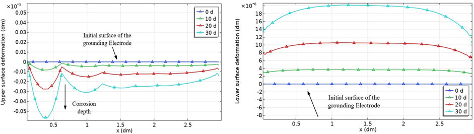
FIGURE 1. Model of corroded ground electrode: (A) Grounding electrodes solution; (B) Deposition of corrosion products.
It can be seen from Figure 1, the solution and deposition of corrosion products jointly lead to the deformation of the grounding electrodes. The volume of corrosion products is larger than that of the grounding electrode material, therefore, the volume expansion characteristics should be considered when building the grounding electrode model. Literature (Dan et al., 2020) proposed that the volume expansion coefficient is the ratio between the volume of corrosion products and the dissolved volume of the grounding electrode, and the basic distribution was found to be 2.79–2.93 through experimental measurement. In the subsequent analysis, the measured average value of 2.87 is used as the volume expansion coefficient of corrosion products. Supplementary Figure S2 shows the model construction of the corroded grounding electrode.
The volume of the dissolved part of the grounding electrode is
The volume of the corrosion product is
According to the definition of the volume expansion coefficient, Eq. 3 can be derived:
Eq. 4 can be obtained from Eq. 3:
Therefore, the real thickness of the corrosion layer considering the expansion of the corrosion products can be calculated.
2.2 Calculation method of power-frequency grounding resistance of corroded grounding electrode
The increment of power-frequency grounding resistance of the corroded grounding electrodes comes from two aspects: 1) The adhesion of corrosion products affects the discharge of the grounding electrodes. 2) The decrease in effective diameter leads to a decrease in the discharge area. R1 is the corrosion product resistance and R2 is the grounding electrode metal discharge resistance.
R1 is the resistance of a hollow ring column along the radial direction, so its calculation formula can be obtained through integration as shown in Eq. 5.
Corrosion products occupy part of the soil discharge space, so R2 needs to subtract a hollow ring column resistance with soil as the medium. As shown in Eq. 6.
Therefore, the calculation method of the power-frequency grounding resistance of the corroded grounding electrode is shown in Eq. 7:
2.3 Calculation method of impulse grounding impedance of corroded grounding electrode
2.3.1 Determination of discrete frequency range
The lightning current function in this paper is used the Heidler-type formula given in the IEC standard (IEC62305-1, 2010):
The wave-front time is 2.6 µs, the half-peak time is 50 µs, and the amplitude is 10 kA.
Where,
Lightning current has a large amplitude and high frequency. To study the discrete spectral characteristics of lightning current, the periodic extension time-domain diagrams of lightning current can be obtained by periodic extension as shown in Supplementary Figure S3.
Supplementary Figure S3 indicates that when the time is greater than 400 µs, the amplitudes of the lightning current tend to be zero. Therefore, the lightning current period T is selected at 400 μs during the periodic extension. The fundamental frequency f of the lightning current after the periodic extension is 2.5 kHz (1/T).
2.3.2 Calculation method of impulse grounding impedance
The impulse grounding impedance is an important technical index that reflects the surge protection performance of grounding electrodes. The impulse grounding impedance refers to the ratio between the impulse voltage amplitude and the lightning current amplitude injected into the grounding electrode. To obtain the impulse grounding impedance, the time domain response of the impulse voltage should be solved. The impulse voltage response of the corroded grounding electrodes satisfies Eq. 10 at different frequency points:
Where, Z is composed of grounding electrode self-resistance, mutual resistance, self-inductance, and mutual inductance between conductor segments (Hu et al., 2022).
The calculation process is shown in Supplementary Figure S4.
3 Sudy on influencing factors of grounding electrodes corrosion state evaluation
This paper choose a 220 kV 2T-FK3 typical tower grounding electrodes structure with square ray, which
The grounding electrode material is round carbon steel, with a relative dielectric constant of 17 and a relative permeability of 636. A coating (Zhang et al., 2020a; Zhang et al., 2020b; Zhang et al., 2020c) is added to the outer layer of the grounding electrodes to simulate the corrosion products. Setting the diameter to 12 mm, 11 mm, 10 mm, 9 mm, 8 mm, 6 mm, 4 mm, and 2 mm, and setting the corrosion layer thickness d to 0 mm, 1 mm, 3 mm, 4 mm, 5 mm, 7 mm, 9 mm, and 10 mm. The microsegment of the square, the radial electrode, and the lead down line are all 0.2 m. The side length of the square is divided into 50 segments and the radial electrode is into 10 segments. The segment of the grounding electrodes is shown in Supplementary Figure S6.
3.1 Analysis of the influence of power-frequency characteristics on a comprehensive assessment of grounding electrode corrosivity
After corrosion, the solution and deposition of corrosion products jointly affect the power frequency grounding characteristics of the ground electrode. To study the discharge capacity law of the corroded grounding electrode surface, the MALZ module of CDEGS is used to simulate. The discharge capacity law of the corroded grounding electrode surface is shown in Figure 2.
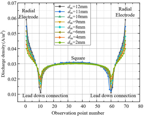
FIGURE 2. The power-frequency discharge characteristics of corroded grounding electrodes.
It can be seen from Figure 2, the discharge capacity at the end of the radial electrode is the largest, and the discharge capacity at the square is small and approximately uniform. As a whole, the grounding electrodes mainly rely on the radial electrode to discharge. At the lead-down connection, the discharge surface distorts and the discharge density reaches its minimum. The corrosion of the grounding electrodes will not affect the overall discharge capacity, but the corrosion layer will weaken the end effect of the current distribution. The thicker the corrosion layer, the smaller the discharge density of the end part of the radial electrodes, and the larger the discharge density of the square. Corrosion leads to the weakening of the discharge capacity of the radial electrode.
The power-frequency grounding resistance is calculated according to Eq 7. The calculation results of low-frequency grounding resistance are shown in Figure 3.
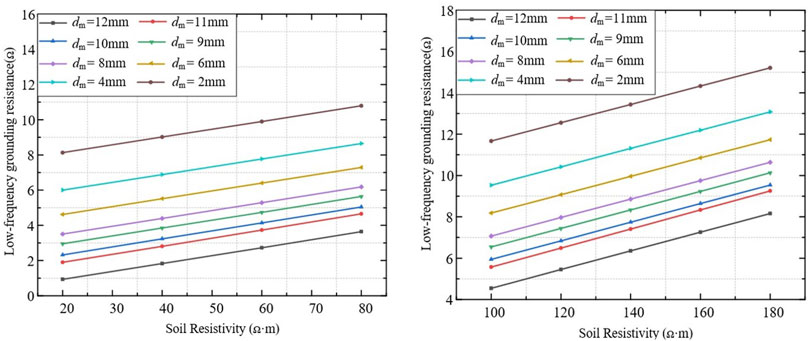
FIGURE 3. Power-frequency grounding resistance of different corrosion degree: (A) 20 Ω·m ≤ ρ ≤ 80 Ω·m; (B) 100 Ω·m ≤ ρ ≤ 180 Ω·m.
Figure 3 shows the calculation results of the power-frequency grounding resistance of the corroded grounding electrode. The power-frequency grounding resistance and soil resistivity are proportional functions. The curves in Figure 3 are approximately parallel, and the power-frequency grounding resistance increases with the increase of the corrosion grades.
3.2 Analysis of the influence of impulse characteristics on a comprehensive assessment of grounding electrode corrosivity
There is usually a great difference between the impulse characteristics and the power-frequency characteristics, and its impulse characteristics contain many high-frequency components. The 12 frequency points (0, 2.5 kHz, 5 kHz, 7.5 kHz, 10 kHz, 12.5 kHz, 15 kHz, 27.5 kHz, 40 kHz, 50 kHz, 90 kHz, 100 kHz) recommended by CDEGS are selected to calculate the amplitude-frequency characteristics of impedance, as shown in Figure 4.
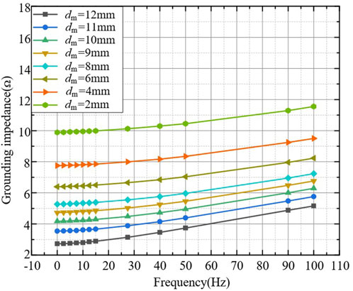
FIGURE 4. The amplitude-frequency characteristics of impedance.
After corrosion, the radius of the grounding electrodes decreases, and since the corrosion product is a non-magnetic and weakly conductive substance, it mainly affects the amplitude of the grounding impedance. The frequency domain impedance of the grounding electrodes changes little in the low-frequency range but increases rapidly in the high-frequency range. Therefore, the corrosion grades cannot be accurately judged only through the power-frequency characteristics.
When lightning current flows through the grounding electrodes, its impulse discharge characteristics are different from power-frequency discharge characteristics. The impulse discharge characteristics of grounding electrodes are shown in Figure 5.
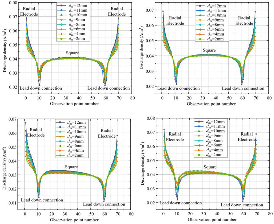
FIGURE 5. Impulse discharge characteristics of corroded grounding electrodes at different frequency points: (A) 2500 Hz; (B) 10 kHz; (C) 50 kHz; (D) 100 kHz.
It can be seen from Figure 5, the corrosion of the grounding electrodes will not affect the overall discharge capacity, but the corrosion layer will weaken the end effect of the current distribution. When the frequency is 0 kHz–10 kHz, the impulse discharge characteristics are consistent with the power-frequency discharge characteristics. However, when the frequency is 50 kHz and 100 kHz, the grounding electrodes have an obvious hindrance effect on the high-frequency impulse current, and the discharge density at the grounding lead-down connection is almost zero. Impulse current only discharge in the effective dispersal area near the grounding electrodes injection point. It can be seen that the discharge density of the grounding electrodes presents an uneven form when the frequency is higher.
The impulse grounding impedance is calculated according to Supplementary Figure S4. The calculation results of impulse grounding impedance are shown in Figure 6.
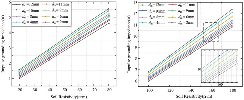
FIGURE 6. Impulse grounding impedance of different corrosion degree: (A) 20 Ω·m ≤ ρ ≤ 80 Ω·m; (B) 100 Ω·m ≤ ρ ≤ 180 Ω·m.
The impulse grounding impedance and soil resistivity are proportional functions. The curves in Figure 6 are approximately parallel, and the impulse grounding impedance increases with the increase of the corrosion grades.
3.3 Determination of minimum safe diameter
After corrosion, the thermal stability of the grounding electrodes will decrease, and the impulse grounding impedance and power-frequency grounding resistance will increase. This situation leads to the deterioration of the discharge capacity. When the thermal stability or discharge capacity decreases beyond the limit, safety accidents are likely to occur. Therefore, it is very important to determine the minimum safety diameter of the grounding electrode.
This paper adopts IEC standard (IEC 60364-5-54, 2011; IEC 61557-5, 2019) as shown in Supplementary Table S1.
According to Figures 3, 6, the impulse grounding impedance and power-frequency grounding resistance increase both increases with the aggravation of the corrosion grades. Figures 3A, 6A show that the power-frequency grounding resistance and the impulse grounding impedance both meet the standards. When the soil resistivity is according to Figures 3B, 6B, power-frequency grounding resistance meets the standards, but the impulse grounding impedance already does not. Therefore, the impulse characteristics should be considered in determining the minimum safe diameter.
On the premise of safe discharge, the literature (Low-voltage electrical installations-Part 5–54.) shows that the grounding electrodes are mainly composed of carbon round steel, which should meet the standards of thermal stability and mechanical strength. Furthermore, the cross-sectional area should be no less than 50 mm2. As shown in Eq. 11.
Eq. 12 can be derived:
Therefore, the minimum safe diameter standards under different soil resistivity conditions are formulated as shown in Table 1.
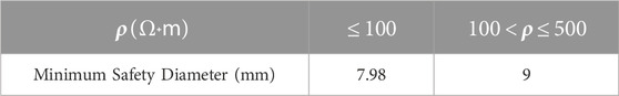
TABLE 1. Minimum safety diameter standard.
When the diameter of the grounding electrode meets the requirement of thermal stability, it should meet Eq. 11. After corrosion, its safety diameter shall be no less than 7.98 mm. Therefore, the minimum safety diameter should consider impulse grounding characteristics, power frequency grounding characteristics, and thermal stability. The determination of the minimum safety diameter proposes in this paper is only applicable to most low-resistance and traditional square beam tower areas. If the current diameter
3.4 Simulation of soil corrosive evaluation factors
The corrosion of grounding electrodes is mainly affected by soil texture, soil resistivity, PH value, salt content, water content, metal corrosion potential, soil
In this section, Supplementary Figure S1 is used to obtain the corrosion rate rule and the change of ion concentration under different PH values, water content, salt content, and soil resistivity after 30 days of natural corrosion, as shown in Figure 7.
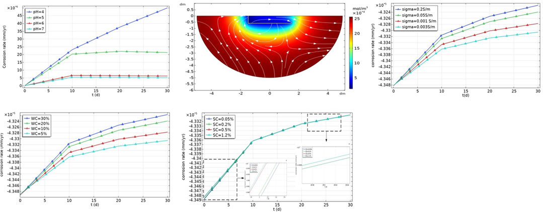
FIGURE 7. The relationship between influencing factors and corrosion rate: (A) Effect of PH value on corrosion rate; (B) Hydrogen concentration after 30 days; (C) Effect of water content on corrosion rate; (D) Effect of salt content on corrosion rate; (E) Effect of soil resistivity on corrosion rate.
It can be seen from Figure 7, the corrosion rate is higher when the soil resistivity and PH value are smaller, and the corrosion rate is higher when the soil moisture content and salt content are higher. The distribution of hydrogen ion concentration indicates that the soil PH near the grounding electrode is higher, which is due to the oxygen reduction reaction generating more hydroxide ions.
The corresponding relationship between each evaluation factor and soil corrosion grades is shown in Supplementary Table S2.
4 Comprehensive evaluation of corroded grounding electrodes considering the impulse characteristics
The existing corrosion assessment methods of the soil environment do not consider the grounding characteristics, and the assessment methods of the grounding electrode corrosion grades also do not consider the soil environmental factors. When the grounding electrodes do not meet the requirements, it has to be replaced. Therefore, in this section, the grounding characteristics and soil environmental factors are considered comprehensively to evaluate the corrosion grades. Based on the fuzzy theory mentioned by literature (Zhang et al., 2020a; Zhang et al., 2020b; Zhang et al., 2020c) and the idea of corrosion evaluation, the minimum safe diameter is combined with corrosion rate as an important parameter for residual life prediction. The comprehensive evaluation of the corroded grounding electrodes model is shown in Figure 8.
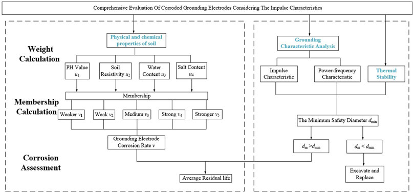
FIGURE 8. The comprehensive evaluation of corroded grounding electrodes model.
4.1 Comprehensive evaluation model of corrosivity considering impulse characteristics
4.1.1 The method of subjective and objective weight integrated weighting
The objective weighting method uses the grey correlation analysis method (Guo et al., 2022) to calculate the objective weight. The subjective weighting method adopts the analytic hierarchy process (Ilham et al., 2022). This paper chooses the comprehensive ensemble weighting method based on the sum of squared deviations to integrate subjective weights and objective weights (Peng et al., 2019).
Let
According to the simple linear weighting method, the comprehensive evaluation value
If matrix B is shown in Eq. 14:
Therefore, the maximum sum of squares of the total deviation of the comprehensive evaluation value is shown in Eq. 15:
Without considering the non-negativity of H, it can be reduced to an unconstrained optimization problem, and Eq. 16 can be simplified as:
According to the relevant knowledge of the Rayleigh quotient in matrix theory, the unit eigenvector corresponding to the maximum characteristic root
4.1.2 Calculation of membership
The weight distribution indicates the influence grades of evaluation factors on the corrosion. To realize a comprehensive evaluation of the corrosion of grounding electrodes, it is necessary to find out the relationship between the corrosion and each evaluation factor. This paper establishes corrosion evaluation factors U = [u1, u2, u3, u4] = [PH, soil resistivity, water content, salt content] and corrosive comments V = [v1, v2, v3, v4, v5] = [weaker, weak, medium, strong, stronger]. The fuzzy matrix of the causticity of grounding electrodes in the soil is established as R, as shown in Supplementary Table S3.
According to the corresponding relationship between soil corrosion grades and each evaluation factor in Supplementary Table S2, parameters in matrix R are calculated by the trapezoidal distribution membership function (Wan et al., 2021).
4.2 A fuzzy comprehensive evaluation of the corrosion grades of grounding electrodes
4.2.1 Corrosion rate assessment of grounding electrodes
The evaluation matrix Y of soil corrosive is obtained
According to the evaluation matrix Y, the corrosion index C is defined to express corrosion. The calculation formula of C is shown in Eq. 18.
C reflects the corrosion strength of the soil environment on grounding electrodes, which is positively correlated with the corrosion rate of the grounding electrodes. According to the literature (Jinl. He, 1998), the relationship between the average corrosion rate of grounding electrodes and soil corrosion is shown in Table 2.
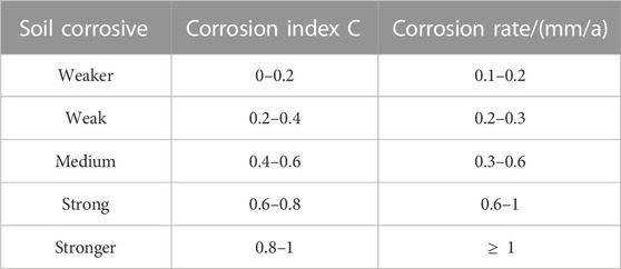
TABLE 2. Soil corrosion and average corrosion rate.
4.2.2 Average residual life prediction of grounding electrodes
After corrosion, the cross-sectional area of the grounding electrodes becomes smaller. As a result, the grounding electrodes cannot meet the standards, and their service life is shortened. If the grounding electrodes are broken due to the current thermal effect, a safety accident may occur. Therefore, it is necessary to predict the average residual life of the grounding electrodes and replace the grounding electrodes in time. The average residual life prediction model of the grounding electrodes is shown in Figure 8.
Corrosion rate and the minimum diameter considering impulse characteristics are important parameters to evaluate the corrosion rate and predict the average residual life of the grounding electrodes. The corrosion rate is related to the corrosion in the soil environment, many influencing factors in the soil environment directly lead to the different corrosion rates of the grounding electrodes, and then determine the service life of the grounding electrodes. This paper uses corrosion rate KH (mm/A) to quantitatively describe the grades of overall metal corrosion. In engineering, the corrosion rate is usually regarded as an important parameter to predict the residual life of the grounding electrode. According to the analysis in Section 2, only the range of residual life of the grounding electrode with diameter
The average residual life (ARL) of the grounding electrodes is calculated by Eq. 19, where dx is the diameter of the grounding electrode meeting the standards, and v is the average corrosion rate. Literature (Jinl. He, 1998) shows that the average corrosion rate of the grounding electrode of carbon steel in the soil is 0.2 mm–0.4 mm/a.
This paper defines the corrosion coefficient
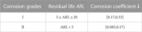
TABLE 3. Classification reference of corrosion grades.
Therefore, according to the comprehensive corrosion evaluation results and the prediction range of the residual life of the grounding electrode, the power department can arrange the operation and transformation plan for the grounding electrodes of the transmission line tower in different areas.
5 Case study
5.1 Verification of the minimum safe diameter
To verify the minimum safe diameter, the transmission line tower is selected for the field measurement experiment. The site measurement diagram is shown in Supplementary Figure S7. The basic parameters of the tower are shown in Supplementary Table S4.
Soil resistivity is measured by the Wenner method. The power-frequency grounding resistance is measured by the sweep-frequency grounding impedance measuring instrument developed by our research group. The impulse grounding impedance is measured by the impulse coefficient method. The results of soil resistivity measurements near the tower and the grounding resistance measurement are shown in Figure 9.
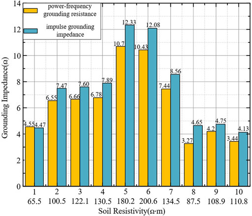
FIGURE 9. Grounding impedance value.
According to Figure 9, the power-frequency grounding resistance meets the standard, but the impulse grounding impedance does not. Therefore, the power-frequency grounding resistance should not be used as the single criterion for corrosion detection. Based on Eq. 7, the corresponding diameter that meets the grounding resistance standards is derived. Figure 10 is the comparison of the diameter of the grounding electrodes.
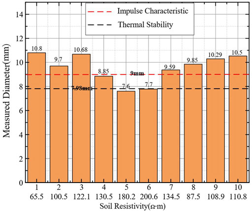
FIGURE 10. Comparison of the diameter of the grounding electrodes.
When the soil resistivity is small and the grounding resistance meets the standards, the minimum safe diameter should be calculated by considering the thermal stability. When the soil resistivity is high, the impulse characteristics and thermal stability should be considered at the same time. This paper verifies the correctness of determining the minimum safety diameter according to the impulse characteristics, thermal stability, and power-frequency characteristics.
5.2 Verification of grounding electrode corrosion assessment method
Supplementary Figure S8A shows that this paper selects eight soil samples near the grounding electrode collected from the transmission line tower. Supplementary Figure S8B shows that the TZS-5 soil multi-parameter comprehensive test system is used to measure soil parameters and electrode corrosion rate. The measurement results of various soil parameters and electrode corrosion rates are shown in Supplementary Table S5, where the corrosion rate is the average value obtained from three measurements.
According to the data in Supplementary Table S5, the corresponding corrosion fuzzy evaluation matrix Y and corrosion index C of carbon steel metal in these eight field soil samples are calculated as shown in Table 4.
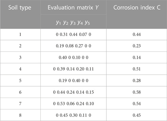
TABLE 4. Sample corrosion evaluation results.
According to Table 4, the corrosion index C is:
Considering the power-frequency characteristics, impulse characteristics, and thermal stability, the minimum safe diameter of the first and fifth grounding electrodes is 7.98 mm, and the minimum safe diameter of the other grounding electrodes is 9 mm. Substitute Eq. 19 successively to calculate its average residual life, as shown in Table 5.
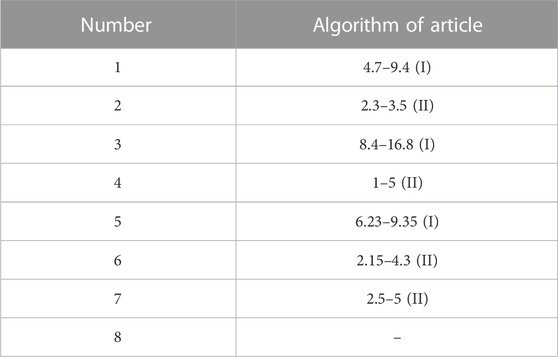
TABLE 5. Range of average residual life ARL of grounding electrodes for three soil types.
According to the experimental soil properties and evaluation results, it can be seen that the No. 6 soil and No. 7 soil has strongly corrosive due to their high water content and salt content. According to Table 5, when power-frequency characteristics, impulse characteristics, and thermal stability are considered, the prediction results will be more accurate.
Therefore, based on the experimental results and on-site analysis, the proposed comprehensive evaluation and prediction method to diagnose the corrosion of the grounding electrodes has high accuracy and high applicability at the site.
6 Conclusion
The existing corrosion assessment methods of the soil environment do not consider the grounding characteristics, and the assessment methods of the grounding electrode corrosion grades also do not consider the soil environmental factors. Therefore, this paper proposes a comprehensive evaluation method for the corrosion of grounding electrodes considering the grounding characteristics and soil environmental factors.
The main results are:
1. There are significant differences between power-frequency characteristics and impulse characteristics. The power-frequency dispersion characteristic is uniform. However, the impulse characteristic has high frequency component, resulting in the dispersion law is not uniform.
2. The effects of soil environmental factors on the electrode corrosion rate are analyzed by simulation. The results show that the corrosion rate is higher when the soil resistivity and PH value are smaller, and the corrosion rate is higher when the soil moisture content and salt content are higher.
3. Based on considering the grounding characteristics, thermal stability, and soil environmental factors, the comprehensive evaluation of corroded grounding electrodes is proposed. The evaluation method is verified by the case study, and the corrosion of carbon steel in eight soil samples is ranked as C6> C7> C4> C8> C1> C5> C2> C3. This method is more comprehensive than other evaluation methods, which can realize trenchless corrosion detection of grounding electrodes.
Therefore, the contribution of this work is shown below. On the one hand, the current corrosion degree of the existing grounding electrodes can be realized under the condition of trenchless. On the other hand, it is of great significance to evaluate and predict the corrosion rate of grounding electrodes in each area for the operation and maintenance of tower.
Data availability statement
The original contributions presented in the study are included in the article/Supplementary Material, further inquiries can be directed to the corresponding author.
Author contributions
XW and YD: Writing the manuscript, conceptualization, investigation, and editing. ZZ and LX: Organizing the database. JD: Checking the manuscript. All authors contributed to the manuscript revision, and read, and approved the submitted version.
Funding
This research was funded by the National Natural Science Foundation of China (NSFC), under Grant no. 52007011. This research was funded by China Postdoctoral Science Foundation under Grant 2021TQ0165.
Conflict of interest
The authors declare that the research was conducted in the absence of any commercial or financial relationships that could be construed as a potential conflict of interest.
Publisher’s note
All claims expressed in this article are solely those of the authors and do not necessarily represent those of their affiliated organizations, or those of the publisher, the editors and the reviewers. Any product that may be evaluated in this article, or claim that may be made by its manufacturer, is not guaranteed or endorsed by the publisher.
Supplementary material
The Supplementary Material for this article can be found online at: https://www.frontiersin.org/articles/10.3389/fmats.2023.1146926/full#supplementary-material
References
IEEE (2012). 81-2012 - IEEE guide for measuring earth resistivity, ground impedance, and earth surface potentials of a grounding system.
Charalambous, C. A., Cotton, I., and Aylott, P. (2008). A simulation tool to predict the impact of soil topologies on coupling between a light rail system and buried third-party infrastructure. IEEE Trans. Veh. Technol. 57 (5), 1404–1416. doi:10.1109/TVT.2007.909312
Dan, Y., Zhang, Z., and Gan, P. (2020). Research on grounding performance of corroded grounding electrodes based on an accurate corrosion model. CSEE J. Power Energy Syst. doi:10.17775/CSEEJPES.2020.03280
Du, J., and Li, N. (2013). A grounding grid model of corrosion factors based on clustering and SVR. J. Inf. Comput. Sci. 10 (16), 5243–5251. doi:10.12733/jics20102745
Guo, A., Kong, D., Zhou, X., Qu, P., Wang, S., Li, J., et al. (2022). Evaluation of material reuse degree in additive manufacturing by the improved resolution coefficient grey correlation method. Process Saf. Environ. Prot. 166, 451–460. doi:10.1016/j.psep.2022.08.026
Hu, Y., Huang, T., An, Y., Feng, J., Cheng, M., Xie, H., et al. (2022). Simulation study on lightning impulse characteristics of flexible graphite composite grounding materials applied to grounding grid of power system. Front. energy Res. 10. doi:10.3389/fenrg.2022.865856
IEC 60364-5-54 (2011). Low-voltage electrical installations-Part 5-54: Selection and erection of electrical equipment– Earthing arrangements and protective conductors.
IEC 61557-5 (2019). Electrical safety in low voltage distribution systems up to 1000 V A.C. and 1500 VD.C. - equipment for testing, measuring or monitoring of protective measures - Part 5: Resistance to earth.
Ilham, Z., Subramaniam, I., Jamaludin, A. A., Wan-Mohtar, W. A. A. Q. I., Halim-Lim, S. A., Ohgaki, H., et al. (2022). Analysing dimensions and indicators to design energy education framework in Malaysia using the analytic hierarchy process (AHP). Energy Rep. 8, 1013–1024. doi:10.1016/j.egyr.2022.07.126
Jiang, Q., and Lu, J. (2021). Defect detection of Pole tower grounding body based on GPR offset imaging. High. Volt. 47 (1), 322–330. doi:10.13336/j.1003-6520.hve.20200507018
Liu, Y., Fang, M., Hu, F., Zeng, S., and Deng, X. (2019). A new design of substation grounding based on electrolytic cathodic protection and on transfer corrosion current. Electr. Power Autom. Equip. 39 (5), 107174–107186. doi:10.1016/j.epsr.2021.107174
Lu, C., Li, L., Liu, Z., Xu, C., Xin, M., Fu, G., et al. (2022). Location and corrosion detection of tower grounding conductors based on electromagnetic measurement. Measurement 199, 111469. doi:10.1016/j.measurement.2022.1.11469
Peng, S., Zhao, Y., Wang, Q., Sha, X., Lv, X., Peng, S., et al. (2019). Stacked ensemble extreme learning machine coupled with Partial Least Squares-based weighting strategy for nonlinear multivariate calibration. Spectrochimica Acta Part A Mol. Biomol. Spectrosc. 215, 97–111. doi:10.1016/j.saa.2019.02.089
Wan, S., Chen, Z., and Dong, J. (2021). Bi-objective trapezoidal fuzzy mixed integer linear program-based distribution center location decision for large-scale emergencies. Appl. Soft Comput. 110, 107757. doi:10.1016/j.asoc.2021.107757
Wang, H., and He, S. (2010). “Predict soil corrosion rate of pipeline steel using ANFIS,” in 2010 International Conference on Computational and Information Sciences, Chengdu, China, 17-19 December 2010, 1045–1048.
wasim, M., and Djukic, M. B. (2020). Long-term external microbiologically influenced corrosion of buried cast iron pipes in the presence of sulfate-reducing bacteria (SRB). Eng. Fail. Anal. 115, 104657. doi:10.1016/j.engfailanal.2020.104657
Xu, S., Li, W., and Wang, Y. (2013). Effects of vehicle running mode on rail potential and stray current in DC mass transit systems. IEEE T Veh. Technol. 62 (8), 3569–3580. doi:10.1109/TVT.2013.2265093
Yamamoto, K., Sumi, S., Sekioka, S., and He, J. (2015). Derivations of effective length formula of vertical grounding rods and horizontal grounding electrodes based on physical phenomena of lightning surge propagations. IEEE Trans. Industry Appl. 51 (6), 4934–4942. doi:10.1109/TIA.2015.2434950
Yin, L., Jin, Y., Leygraf, C., and Pan, J. (2022). A FEM model for investigation of micro-galvanic corrosion of Al alloys and effects of deposition of corrosion products. Electrochimica Acta 192, 310–318. doi:10.1016/j.electacta.2016.01.179
Zhang, Z., Mei, D., Dan, Y., Zou, J., Liu, G., and Gao, C. (2020b). Novel method for diagnosing corrosion of grounding electrodes in soil. Electr. Power Syst. Res. 178, 106049. doi:10.1016/j.epsr.2019.106049
Zhang, Z., Ye, H., Dan, Y., Duanmu, Z., Deng, J., Gao, C., et al. (2020a). Study on corrosion fracture diagnosis method of grounding wire of tower grounding device. Measurement 15, 108213. doi:10.1016/j.measurement.2020.108213
Keywords: grounding electrodes, corrosion, impulse grounding characteristics, minimum safe diameter, comprehensive evaluation
Citation: Wang X, Xiong L, Zhang Z, Dan Y and Deng J (2023) Comprehensive evaluation of corroded grounding electrodes considering the impulse characteristics. Front. Mater. 10:1146926. doi: 10.3389/fmats.2023.1146926
Received: 18 January 2023; Accepted: 24 February 2023;
Published: 08 March 2023.
Edited by:
Peng Wang, North China Electric Power University, ChinaReviewed by:
Jihui Wang, Tianjin University, ChinaShifang Yang, North China Electric Power University, China
Copyright © 2023 Wang, Xiong, Zhang, Dan and Deng. This is an open-access article distributed under the terms of the Creative Commons Attribution License (CC BY). The use, distribution or reproduction in other forums is permitted, provided the original author(s) and the copyright owner(s) are credited and that the original publication in this journal is cited, in accordance with accepted academic practice. No use, distribution or reproduction is permitted which does not comply with these terms.
*Correspondence: Zhanlong Zhang, Wmhhbmd6bEBjcXUuZWR1LmNu