 Ze Chen1
 Wei Li
 Zhiyong Peng
 Duo Xu
- 1State Key Laboratory of New Textile Materials and Advanced Processing Technologies, Wuhan Textile University, Wuhan, China
- 2College of Materials Sciences and Engineering, Wuhan Textile University, Wuhan, China
- 3Hubei Key Laboratory of Digital Textile Equipment, Wuhan Textile University, Wuhan, China
A novel composite yarn with a novel structure is prepared by the three-strand conversion method of double polymer filaments to staple fiber, that is, double polymer filaments to staple fiber repeated migration movement. The geometric principle of different relative positions of filament to helix structure change is analyzed theoretically, and the effect of filament position on the spinning-triangle of composite yarn is demonstrated. Furthermore, the structure of six different composite yarns is modeled and compared with each other, which shows the influence of different filament helical structures on the performance of spinning composite yarns. The repeated migration of filaments is observed using the online observation technique in the dynamic rotating triangle region. In addition, changes in yarn structure are caused by different geometric configurations. The results show that the stem, strength, and hair of six new composite yarns with different helical structures are slightly weakened. In summary, the three-strand conversion method is an effective new method to control the structure of filament and staple fibers.
1 Introduction
As the basis and one of the key processes of the textile industry, spinning affects or even determines the quality of yarn after forming, thus affecting the quality and performance of the final product. Such uncertainty affects the production of textile products that meet people’s needs (Xu et al., 2022a). Unfortunately, natural staple fibers have some hard-to-cover defects, such as weak cohesion, irregular length, etc., which make them unable to fit perfectly with the yarn body, resulting in a rough surface and deteriorating performance of the yarn body (Xia et al., 2020). To solve the above problems, the filament can be used to control the staple fibers in the yarn-forming area, so that the staple fibers exposed to the yarn body can be tightly fitted to the yarn after being wound by a filament.
Filament has the characteristics of continuity and smoothness, although the natural fiber has some defects, relatively it also has the advantages of good hand feel, moisture absorption, and so on. Composite spinning technology can combine the characteristics of filament and natural fibers, so that spinning has both advantages and even has its unique structure (Xia et al., 2019a; Xu et al., 2022b).
At present, the ring-spindle composite spinning technology mainly controls the spinning triangle region and controls the convergence of filament and short chain by configuration in the middle, including corefil spinning (Xia et al., 2018; Xia et al., 2019b; Erbil et al., 2022), sirofil spinning (Jou et al., 1996; Matsumoto et al., 2014; Naeem et al., 2019), fancy spinning (Grabowska, 2010), cluster spinning (Sen et al., 1982), and embeddable and positioning spinning (Sawhney et al., 1989; Subramaniam and Natarajan, 1990; Wang et al., 2012a).
In corefil spinning, a filament is centered, and the filament is wrapped around the filament in the form of a filament bundle, and finally wrapped around the filament to form a sheath structure yarn with the filament as the core. As a result, corefil spinning has a high strength characteristic and a hairy appearance (Liu et al., 2007; Musha, 2008). Filament and staple fibers are not inherently cohesive, so they may slip, leaving part of the filament un-wrapped and the filament exposed. This will not only make the appearance of the yarn ugly but also reduce the mechanical properties of the yarn (Wang et al., 2012b). Sirofil spinning leaves a space in the spinning triangle of the front roller clamp, allowing a strand of staple and filament to be wrapped around the yarn rod in an even spiral structure (Gharahaghaji et al., 2010; Erbil et al., 2022). But the filament does not fully grip the staple fibers of the sirofil yarn, and the fabric is easily damaged when stretched (Wang and Chang, 2003).
In order to solve the above problems, the design of three shares reform law can effectively improve the above problems. Three strands transformation method uses three groups of staple fibers and fine fibers for composite spinning, which can effectively improve the coating rate of staple fibers and reduce the relative slip. Cluster spinning can produce yarns tightly packed with sub-filaments, but the friction between staple fibers and filaments is greater (Tian and Wang, 2005). The filament will be divided into parallel sub-fibers by the separation roller before entering the pre-pinching, and the staple fibers in the yarn-forming area are easier to be clamped. At the same time, it has been shown that two effective methods of capturing staple fibers are implantable and locatable spinning, in which two sets of pre-twisted strands are clamped by two long fibers (Pourahmad and Johari, 2011; Chen et al., 2012; Hua et al., 2018).
In this paper, the relationship between the structure and property of composite yarn is discussed. The spinning model of single composite material is studied. We find that yarn structure plays a crucial role in yarn property. Therefore, the combination and distribution of staple fiber and filament affect the performance of composite yarn and even determine the performance of composite yarn. At the same time, the new composite yarns of different shapes are modeled one by one and compared with other composite yarns. In the spinning process of the co-eccentric device, the influence of the spiral structure formed by the filaments on the performance of the yarn is analyzed theoretically. On the basis of these, the preparation experiment of composite yarn is carried out by using the designed configuration. Finally, the properties of the yarn, such as apparent structure, hairiness, and unevenness, are measured.
2 Theoretical considerations
2.1 Geometrical principle of yarn structure variations caused by reciprocating migrations of filaments wrapping onto staple strands
In the conventional spinning theory, the shape control of the spinning triangle is thought to be determined by the relative position change between the filament and staple fiber (Tang et al., 2004). When the staple fiber is stretched from the front roller tooth, the two strands of staple fiber and fine fiber will intertwine with each other on the yarn surface, so a very obvious and complex spiral structure will be formed in the spinning triangle. In addition, due to the constant relative position change between staple fiber and fine fiber, the spacing and Angle of the spiral structure will also change. Constantly changing the position of the fine fiber may lead to local knotting or excessive wrapping, and even affect the tensile balance of the spinning triangle, affecting the related performance of the yarn. It is worth mentioning that because of the problems mentioned above, the protruding filaments can be easily caught. But the coiled helical structure can only fasten the surface fibers, and cannot exert certain control over the inner fibers (Jaouachi et al., 2011). However, a certain amount of filament can be embedded in the core yarn body to improve internal strength utilization. Therefore, if the two methods of embedding and wrapping are used at the same time, it is beneficial to clamp the staple fibers inside and outside the yarn (Beltran et al., 2007). The trapping capacity of two wound fibers is obviously higher than that of a single fiber, so a single wound fiber will give the surface of the fiber an uneven hair like structure, and easily disintegrate in the process of repeated use.
While two filaments can constantly change the configuration of the yarn through the short chain, the two filaments can also change the Angle and spacing of the helix. Further, the structure of the yarn can be controlled by adjusting the dynamic position of the filament, and thus the properties of the yarn (including hairiness, unevenness, and stretching) can be adjusted.
As shown in Figure 1, shows the reciprocating motion of the composite rotating triangle as it makes contact with the staple fiber and two filaments.
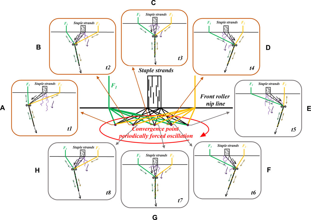
FIGURE 1. Geometric illustration of fibers trajectory: (A-H) shows two filaments wrapped around a short chain to form a spiral structure.
To strengthen the wrapping of staple fibers and make use of the characteristics of staple fibers, a new structural composite yarn is constructed by using a single staple fiber and two equally adjustable filament fibers. The filament realizes dynamic position changes around the staple fibers, as shown in Figure 1. Green filaments (denoted F1) represent the first filament wrapped into a single staple strand (S) and yellow filaments (F2) represents the other filament further wrapped into a twisted composite yarn (Figure 1A). When t2 is reached, both wires (F1 and F2) shift to the right at the same time, and F1 begins to converge and wrap with S further, wrapping F2 into the twisted composite yarn (Figure 1B). Subsequently, F1 and F2 continue to move until the hinges formed by F1 and F2 are symmetrical with the single short chain, so that F1 and F2 cycle back and forth and wind around S to form a uniform helical structure (Figure 1C). Then, F1 and F2 migrate to the right successively; Throughout the move to the right, F2 is always wrapped around S first, followed by F1 around the pre-twisted composite yarn. In Figure 1D, F1 is not on the right side of S and F2 is on the left side of S (Figure 1E). At this time, F1 and F2 change their moving directions from right to left. When the time reaches t6, the spinning triangle of the composite yarn (Figure 1F) is similar to that of (Figure 1D). During the migration of F1 and F2 from t6 to t7, F1 and F2 are again symmetrically hinged with S (Figure 1G). After F1 first merges with S, F2 will continue to wrap around the pre-twisted composite yarn (Figure 1H). After one cycle, a new filament winding structure is created, that is different from the past.
2.2 Analysis of the influence of different wrapping methods on the shape of the triangle of a composite yarn
To better explain the new structure composite yarn and its preparation method, and then compare the structure difference with other composite yarns, the influence of structure difference on yarn performance is discussed. According to the different positions of filament and staple fibers in the yarn-forming triangle shown in Table 1, six kinds of composite yarn models in the shape of filament positioning are established, and the experimental design is carried out on this basis.
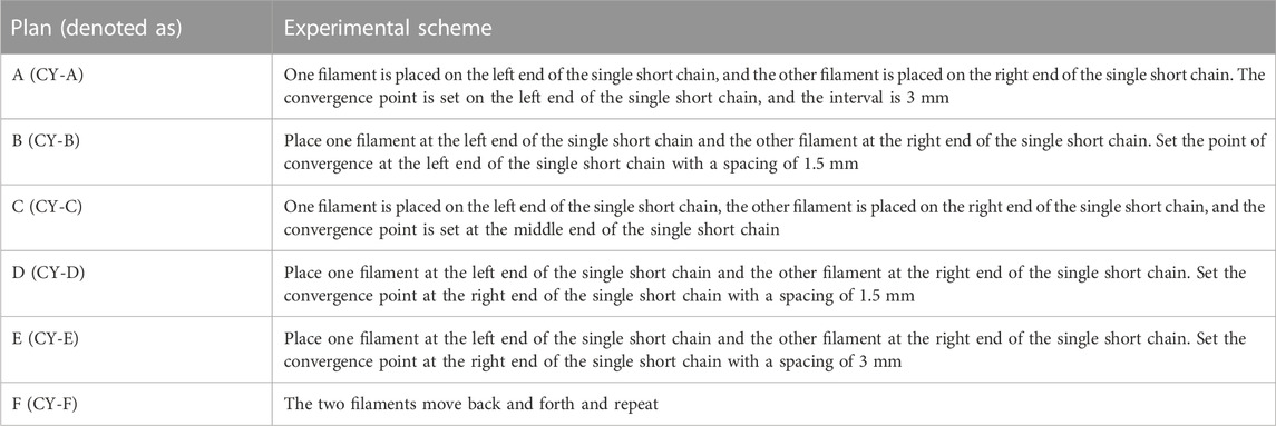
TABLE 1. Experiment design of composite yarns.
Six kinds of composite yarn models in the shape of filament positioning are established, and the experimental design is carried out on this basis.
Figure 2 shows the composite yarn model designed and spun by different relative positions of filament and staple fiber strands. As can be seen in Figure 2A, the single text stretching results in the formation of asymmetrical rotating triangles and different blending angles at the twist points due to the different distances of the convergence points. The right filament firstly wrapping onto the staple strand, because the right filament has more tensile. As shown in Figure 2B, The left filament is wrapped around the staple before the right filament, forming a small spinning triangle with the staple in the spinning area. Subsequently, the right filament will be wound around the short yarn in the spinning area, forming the main spinning triangle with the staple fiber. Different from the above, the convergence point of the spinning triangle formed by the two filaments and staple fibers are located in the middle of the staple fibers. Since the left and right filaments can give the same winding force, the balance is achieved and a symmetrical state is presented (Figure 2C). Meanwhile, at the convergence point which is on the right of the staple strand, the right filament is wound around the staple before the left filament, forming a small spinning triangle with the staple in the spinning area and the pre-twisted yarn and left filament to constitute the major spinning triangle (Figure 2D). As shown in Figure 2E, the left filament first wraps onto the staple strand, because the left filament has more tensile. Additionally, due to the constant reciprocating motion of the two filaments, the rotating triangle of the yarn formation zone changes constantly, as shown in Figure 2F.
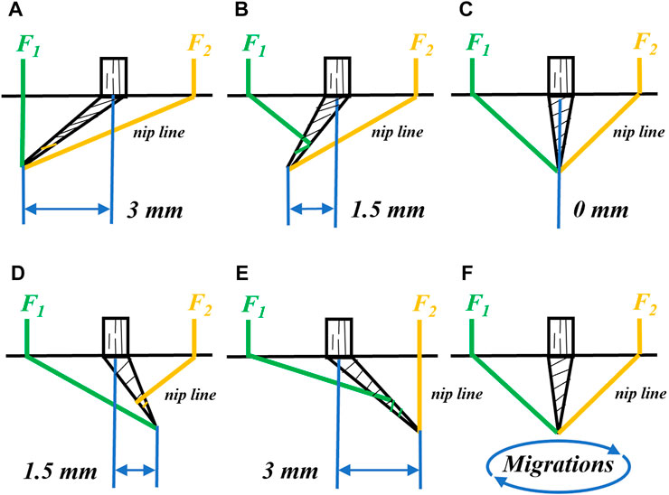
FIGURE 2. Specific diagrams of the different options of composite yarns in the forming zone: (A) CY-A; (B) CY-B; (C) CY-C; (D) CY-D; (E) CY-E and (F) CY-F.
2.3 Comparative analysis of different spiral structure models for the formation of composite yarns with two filament-controlled short chains
Combined with the triangle shape in the spinning process and the fiber transfer theory in the spinning area, the geometric model of filament and staple fibers in the composite yarns after yarn forming can be further predicted, that is, the yarn structure. As shown in Figure 2, after the front pinch, the two filaments and staple strands will be twisted in the triangle area to form initial convergence. Fibers and filaments pass through a series of reciprocating movements to form a variety of composite yarn structures.
It can be clearly observed that the filament helices presented by scheme A and scheme yarn are not the same (Figures 2A, B), mainly reflected in the space occupied by the filament helices and the Angle of inclination. Therefore, the two pairs of compact filaments interweave together, which can effectively capture the protruding staple fibers.
When F1 or F2 is wrapped around S at the same time, the two symmetrical filaments can be tightly wrapped around the yarn surface, so they have strong fiber interception ability (CY-C; Figure 2C).
The spiral spacing and angle of CY-D (Figure 2D) and CY-E (Figure 2E) changed periodically from low-density spiral to dense spiral, which is due to the change of the junction position of the two filament and yarn rod, the prominent staple fibers are fully captured, and the surface roughness is reduced, smoothness is increased.
As the triangular shape of the yarn-forming area is constantly changing, the spacing and Angle of the spiral structure formed by the filament during the wrapping process are different, which makes the different structures generated by each scheme become the characteristics of the yarn (CY-F; Figure 2F).
Figure 3 shows the structural model of composite yarns made of filament and staple fibers at different relative positions, and shows the possible appearance structure of different composite yarns (Scheme A–F).
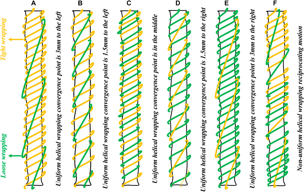
FIGURE 3. Illustration of the variation in the structure of the spiral formed by the compound yarns of the different schemes: (A) CY-A; (B) CY-B; (C) CY-C; (D) CY-D; (E) CY-E and (F) CY-F.
3 Materials and methods
3.1 Material preparation
The filaments are made from commercially available polyester fibers (as shown in Figure 4A). The advantages of polyester fibers are their high strength, moderate elongation, good abrasion resistance, and chemical stability, etc. While changing the structure of the composite yarn, they can also give the composite yarn certain good properties, which are conducive to the application of the composite yarn on many occasions.
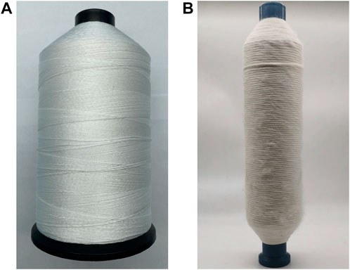
FIGURE 4. Two experimental spinning materials: (A) polyester yarn and (B) cotton fiber.
Staple fibers are also used in the more widely used cotton fibers (as shown in Figure 4B). Although cotton fibers are prone to wrinkling and deformation after washing and repeated wear, the addition of cotton fibers also gives the fabric the advantages of good breathability, moisture absorption, and comfort, so the addition of cotton fibers to the composite yarn is beneficial to the wider application of the composite yarn.
3.2 Experiment details
Based on the above model structure, a threaded rod with a pitch of 1 mm would be used to exactly satisfy the requirements for filament feeding position control in the experimental design of composite spinning. To install a simple homemade device behind the front nip line (mounted on the Dssp-01 digital spinning frame made by Jiacheng Machinery & Electronics), which dynamically varies the position of the two filaments (as shown in Figure 5) when the two filaments undergo reciprocal movement from the front nip line, causing a cyclical change in the wrapping and winding structure of the filaments and staple fibers in the yarn formation zone.

FIGURE 5. A simple homemade device for migrations of convergence point.
Thereafter, 710tex cotton roving (produced by Dongguan Desvenka Textile Co., Ltd.) and two different colors (black and yellow) of polyester filament yarns of type (black and yellow) 80D/24F (supplied by Suzhou Shunqi Textile Technology Co., Ltd.) are used to produce different composite yarns. The specific process factors are as follows: total draft 30.1; bar spacing 3.0 mm; front roller speed, 11.99 m/min; twist factor 298; spindle speed, 5800 rpm; collar type PG 1/23854 and wire loop type 69034/0.
Each sample of all composite yarns must be stored under specific conditions (temperature t = 20°C, relative humidity RH = 65%, standard atmospheric pressure) for not less than 24 h. Then, the characterization properties of the yarns are tested. The twisted triangle shape changes of the new structured composite yarn are recorded by Huawei Mate 50 camera photos, and the microstructure is observed by RH-2000 automatic electron optical microscope measurements. The hairiness test is performed by H400 hairiness meter, which randomly measured 10 m at a speed of 30 m per minute, followed by five repetitions and the average value is obtained. The tenacity of the composite yarn is tested using YG068C single yarn tensile strength tester and the average value is taken for 20 times. Unevenness and defects of all samples are evaluated using the E500 capacitive uniformity tester at a speed of 400 m per minute for 1 min, according to the test requirements of CN GB/T 3292-1997.
4 Results and discussion
4.1 New structural composite yarn formed by forced migration of two filaments in the forming zone
As illustrated in Figure 6, the cyclic variation of the twisting triangle due to the translating gear and the repeated migration of the convergence point directly causes their twisting triangle to change as a result of the different stresses to which they are subjected.
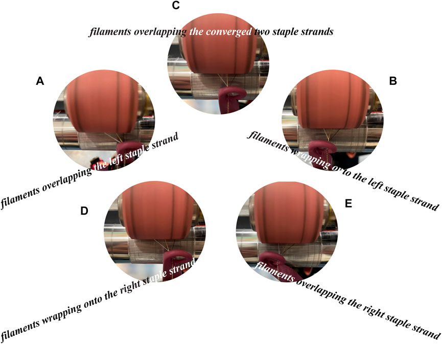
FIGURE 6. Forced migrations of combined filaments during composite siro-spinning: (A) filaments overlapping the left staple strand; (B) filaments wrapping onto the left staple strand; (C) filaments overlapping the converged two staple strands; (D) filaments wrap-ping onto the right staple strand and (E) filaments overlapping the right staple strand.
Figures 6A, B illustrate that the convergence point moves to the far left, and the geometry of the spinning-triangle zone appears as an asymmetrical triangle, that is offset to the left. This is due to the left filament has more tension, which corresponded to the predictive model Figures 1A, B. Another situation exhibited the spinning-triangle zone is rendered as an equilateral triangle zone (Figure 6C). The reason for it is the staple stand suffered the most downward tension, and the two filaments have equal tension. Further, the geometry of the spinning-triangle zoon has been changed as an asymmetrical triangle which is offset to the right (Figures 6D, E). This might result from the right filament is closer to the convergence point, it is subjected to greater downward tension, which ultimately leads to a change in the geometry of the spinning-triangle zone.
4.2 Appearance comparisons of yarns spun by the different positions of convergence point
In the spinning-triangle zone, the geometrical configuration between the two filament and staple fibers is different, which will cause the yarn structure to change.
Based on Figure 7, it is apparent that the surface hair of CY-A and CY-E yarns is less than others (25.8, 29), filaments are more tightly wound, and yarns exhibit a uniform helical structure (Figures 7A, E). This may be caused by different filament tensions in the yarn formation zone, where the left filament (CY-A) or the right filament (CY-E), which is subjected to the same direction of force as the yarn drafting, is under the greatest tension, resulting in a uniform helical structure on the yarn surface. At the same time, because the unilateral filament has a higher tension, it makes the higher tension filament first and the staple yarn closely wrapped, which effectively controls the hairiness on the surface of the yarn.
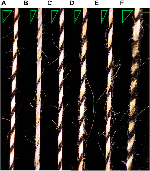
FIGURE 7. Comparison of the structural appearance of the different scheme compound yarns: (A) CY-A spun yarn; (B) CY-B spun yarn; (C) CY-C spun yarn; (D) CY-D spun yarn; (E) CY-E spun yarn and (F) CY-F spun yarn.
Unlike CY-A and CY-E, in CY-B and CY-D systems, the convergence point is shifted, resulting in a change in the tension on the filament and staple strand from the filament near the convergence point being under the greatest tension to the staple strand being under a similar tension to that of the filament. Since the filament near the convergence point and the staple strand are under similar stress, this filament first wraps with the staple strand and then converges with another filament, forming a helix structure with wide spacing on the surface of the yarn (Figures 7B, D), but the latter filament is under less tension and cannot effectively lock the hairiness on the surface of the staple yarn (46.2, 41.6).
Expectedly, the CY-C exhibited apparent uniform helical wrapped, showing equal helix space (Figure 7C), and less hairiness on the yarn surface (38.6), which is due to the fact that when the convergence point is located directly below the staple strand, the filaments on both sides are under equal tension, while the staple strand is under the same direction of force as the draft, so the staple strand is under the greatest tension.
It is worth noting that in the newly structured composite yarn (CY-F), the filament helix changes periodically with the reciprocal migration of the convergence point, Notably, in the composite yarn of the new structure (CY-F), the filament helix changes periodically with the reciprocal migration of the convergence point as shown in Figure 7F, owing to the continuous dynamic changes of the tension within the spinning-triangle. The composite yarn with the novel structure has moderate yarn hairiness (35.8) due to the different tightness of the filament-wrapped winding. Such results also verify the accuracy of the theoretical analysis.
4.3 Comparison of hairiness of yarns spun by the different positions of convergence point
Table 2 shows the surface hairiness of the composite yarns spun by each option; the surface hairiness is reduced by the spiral structure formed by the two filaments wrapping around the short chain. In contrast, the different relative positions of the convergence points also have an effect on the hairiness, with less hairiness being produced on yarns with more distant convergence points; this is probably due to the fact that the more distant convergence points generate more torque, which is conducive to a tighter spiral structure. If the two filaments only move back and forth, the resulting spiral structure is not so tight as to wrap around the protruding staple fibers and therefore the CY-F surface is the roughest. This result corroborates the analysis well against the previous theoretical analysis.
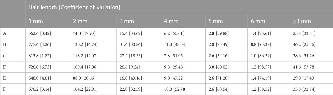
TABLE 2. Hair number comparison of different composite yarns.
4.4 Comparison of evenness of yarns spun by the different positions of convergence point
According to Table 3, CY-A has a higher degree of irregularity (8.93) compared to other composite yarns. This may be caused by excessive filament tension. Excessive filament tension can contribute to severe irregularities and occasional complete loss of staple fibers, increasing yarn imperfections and producing thick and thin areas. Moreover, the Z-twist is easily transmitted to the left part of the spinning triangle; based on this mechanism, the low-twisted fibers of CY-A will be wrapped around the tightly twisted staple fibers (in contrast to the case of CY-E) with a relatively larger and tighter wrapping area, leading to an increase in yarn unevenness. Therefore, the spun yarn unevenness CVm value decreased with the same CY-E setting (8.85).

TABLE 3. The unevenness of different composite yarns.
Under a similar fiber trapping situation, CY-B and CY-D have lower unevenness (8.52, 8.46) than CY-A and CY-E, which may be due to the change in filament tension caused by the change in convergence point. As the convergence point moves inward, the filament tension decreases away from the staple strand, while the filament tension increases closer to the staple strand, and the wrapping tightness decreases compared to CY-A and CY-E.
CY-C has the lowest unevenness CVm value (8.39) due to the convergence point moving directly below the staple strand and the filament tension being uniform on both sides. The uniform tension of the filaments on both sides leads to the same tightness of the staple strands wrapped by both filaments resulting in the lowest unevenness in CY-C.
Table 3 also shows that medium CVm values (8.30) can be obtained with the new composite yarn (CY-F). This is due to the dynamic change in filament tension on both sides due to the dynamic change in the convergence point which causes the tightness of the filament wrapped around the staple strands on both sides to change continuously. As expected, the results are consistent with the previous theoretical analysis.
Moreover, the evenness of the six composite yarns could be visualized in Figure 8; different composite yarns exhibit various wavy network structures and inconsistent spiral trajectories.
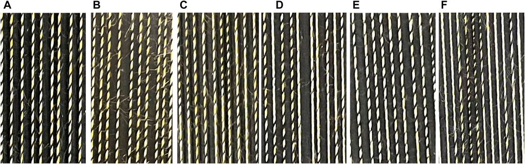
FIGURE 8. Comparison of evenness properties of the different scheme compound yarns: (A–F) show the respective uniformity of different compound yarns on a black background.
4.5 Comparison of tensile properties of yarns spun by the different positions of convergence point
In this novel composite yarn, a variety of structures, which combined the various structures of composite yarn spun with Plan A-F, changed with the convergence point position.
Table 4 shows that yarn-breaking elongation and work showed similar patterns to yarn tenacity results.
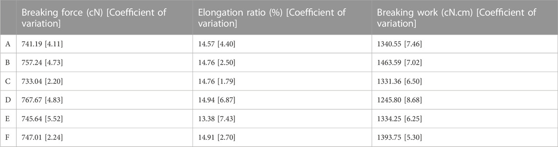
TABLE 4. Tensile property of different composite yarns.
5 Conclusion
In order to improve the synergy between filament and staple fibers, herein two filaments are employed to make repeated migration movements to spin a composite yarn with a completely novel structure.
The theoretical analysis demonstrates that different helical structures could improve the apparent structure and the mechanical properties of the yarn; moreover, the different filament helical structures on the newly structured composite yarn are formed by the reciprocal motion of a pair of filaments, which slightly weakens the ability to lock the staple fibers in the middle of the twisting triangle. In this study, a total of six composite yarn structure models are used to specifically compare the effects of different filament spiral structures on composite yarn properties for spinning with a homemade device to control the reciprocal migration of two filaments.
The dynamic changes of the twisting triangle of the new composite yarn indicated that the two filaments kept moving laterally repeatedly during the yarn formation. As seen from the yarn characterization, the new structure composite yarn revealed different sizes of helix angles on the yarn, which is mainly due to the helix structure formed during the filament movement. Experimentally, six groups of composite yarns are characterized and compared, and the new composite yarns showed slightly weakened stem, strength, and hairiness, and the experimental results are in good agreement with the theoretical analysis. In addition, the method helps to control the structure of filaments and staple fibers, which is a guideline for the improvement of composite yarn structure. In the future, the effect of different types and counts of filaments on the yarn structure can be explored.
Data availability statement
The original contributions presented in the study are included in the article/Supplementary Material, further inquiries can be directed to the corresponding authors.
Author contributions
ZC, WL, and ZP contributed equally to this article. ZC, RZ, WX, and DX conceived and planned this research. ZC, WL, ZP, and DX performed the experiments. RZ and WX performed the stress analysis. ZC, WL, ZP, YL, and DX organized the data and wrote the manuscript. All authors contributed to manuscript revision, read, and approved the submitted version.
Funding
The study was financially supported from the National Natural Science Foundation of China (Nos. U21A2095 and 52203373), the Postgraduate Research & Practice Innovation Program of Jiangsu Province (No. KYCX22_3203), and the Key Research and Development Program of Hubei Province (No. 2021BAA068).
Acknowledgments
We acknowledge the State Key Laboratory of New Textile Materials and Advanced Processing Technologies.
Conflict of interest
The authors declare that the research was conducted in the absence of any commercial or financial relationships that could be construed as a potential conflict of interest.
Publisher’s note
All claims expressed in this article are solely those of the authors and do not necessarily represent those of their affiliated organizations, or those of the publisher, the editors and the reviewers. Any product that may be evaluated in this article, or claim that may be made by its manufacturer, is not guaranteed or endorsed by the publisher.
Supplementary material
The Supplementary Material for this article can be found online at: https://www.frontiersin.org/articles/10.3389/fmats.2023.1171786/full#supplementary-material
References
Beltran, R., Wang, L., and Wang, X. (2007). A controlled experiment on yarn hairiness and fabric pilling. Text. Res. J. 77, 179–183. doi:10.1177/0040517507079409
Chen, J., Xu, Q. L., Xia, Z. G., and Xu, W. (2012). An experimental study of influence of filament and roving location on yarn properties during embeddable and locatable spinning. Fiber Polym. 13, 1196–1200. doi:10.1007/s12221-012-1196-3
Erbil, Y., Islam, R., Babaarslan, O., and Sırlıbaş, S. (2022). Effect of structural changes on the cotton composite yarn properties. J. Nat. Fibers 19, 1899–1907. doi:10.1080/15440478.2020.1788687
Gharahaghaji, A. A., Zargar, E. N., Ghane, M., and Hossaini, A. (2010). Cluster-spun yarn—A new concept in composite yarn spinning. Text. Res. J. 80, 19–24. doi:10.1177/0040517508099916
Grabowska, E. K. (2010). Mathematical basis for classification of twisted multiplied fancy yarns. Text. Res. J. 80, 1768–1776. doi:10.1177/0040517510369407
Hua, T., Wong, N. S., and Tang, W. M. (2018). Study on properties of elastic core-spun yarns containing a mix of spandex and PET/PTT bi-component filament as core. Text. Res. J. 88, 1065–1076. doi:10.1177/0040517517693982
Jaouachi, B., Moussa, A., Hassen, M., and Sakli, F. (2011). Image analysis of the elastane position effect on the appearance of wet pneumatic spliced elastic core-spun yarn. Text. Res. J. 81, 1460–1469. doi:10.1177/0040517511398948
Jou, G. T., East, G. C., Lawrence, C. A., and Oxenham, W. (1996). The physical properties of composite yarns produced by an electrostatic filament-charging method. J. Text. I. 87, 78–96. doi:10.1080/00405009608659058
Liu, W. Y., Yu, Y. P., He, J. H., and Wang, S. Y. (2007). Effect of strand-spacing between roving and filament on sirofil yarn properties. Text. Res. J. 77, 200–204. doi:10.1177/0040517507080614
Matsumoto, M., Matsumoto, Y., Kanai, H., Wakako, L., and Fukushima, K. (2014). Construction of twin staple-core spun yarn with two points of yarn formation in one twisting process. Text. Res. J. 84, 1858–1866. doi:10.1177/0040517513499435
Musha, T. (2008). Spinning tension on ring spinning frame. J. Text. Eng. 4, 21–26. doi:10.4188/jte1955.4.2_21
Naeem, M. A., Akankwasa, N. T., Leroy, A., Leroy, A., Siddiqui, Q., and Ahmad, A. (2019). A study of novel multifilament spreading and feeding method, to produce filament wrapped-staple core composite yarn using modified ring frame. J. Text. I. 110, 378–385. doi:10.1080/00405000.2018.1480342
Pourahmad, A., and Johari, M. S. (2011). Comparison of the properties of ring, solo, and siro core-spun yarns. J. Text. Inst. 102, 540–547. doi:10.1080/00405000.2010.498170
Sawhney, A. P. S., Robert, K. Q., and Ruppenicker, G. F. (1989). Device for producing staple-core/cotton-wrap ring spun yarns. Text. Res. J. 59, 519–524. doi:10.1177/004051758905900905
Sen, A., Gupta, V. B., and Sengupta, A. K. (1982). False-twist textured poly (ethylene terephthalate) slit film yarn. Text. Res. J. 52, 710–713. doi:10.1177/004051758205201105
Subramaniam, V., and Natarajan, K. S. (1990). Frictional properties of siro spun yarns. Text. Res. J. 60, 234–239. doi:10.1177/004051759006000407
Tang, Z., Wang, X., Fraser, W. B., and Wang, L. (2004). An experimental investigation of yarn tension in simulated ring spinning. Fiber Polym. 5, 275–279. doi:10.1007/bf02875525
Tian, W., and Wang, X. (2005). Study on sirofil spinning technology and yarn structure. Shanghai Wool. Linen Sci. Technol. 2, 16–18.
Wang, H., Xia, Z., and Xu, W. (2012). A study of an embeddable and locatable spinning system via quasi-static mechanical analysis. Text. Res. J. 82, 2071–2077. doi:10.1177/0040517512452946
Wang, H., Xia, Z., and Xu, W. (2012). A study of an embeddable and locatable spinning system via quasi-static mechanical analysis. Text. Res. J. 82, 2071–2077. doi:10.1177/0040517512452946
Wang, X., and Chang, L. (2003). Reducing yarn hairiness with a modified yam path in worsted ring spinning. Text. Res. J. 73, 327–332. doi:10.1177/004051750307300409
Xia, Z. G., Guo, Q. S., Ye, W. X., Chen, J., Feng, S. L., and Ding, C. (2018). Comparative study of fiber trapping by filaments in conventional and diagonal Sirofil systems. Text. Res. J. 88, 1581–1592. doi:10.1177/0040517517703606
Xia, Z. G., Tang, J. D., and Ye, W. X. (2019). A novel concept to produce periodic varied structural composite yarn via cyclical changing of the spacing between filaments and the strand. Text. Res. J. 89, 2998–3006. doi:10.1177/0040517518805384
Xia, Z. G., Wang, S. H., Wei, J., and Xu, W. L. (2019). Novel composite siro-spinning with forced migrations of filaments. Text. Res. J. 89, 3927–3936. doi:10.1177/0040517518824850
Xia, Z. G., Wang, S. H., and Ye, W. X. (2020). A method to produce ring single yarn with fancy and anti-frictional structure by feeding filaments in front of the front roller nip. Text. Res. J. 90, 631–640. doi:10.1177/0040517519877466
Xu, D., Fan, H., Yang, W., Liu, K. S., and Xu, W. L. (2022). Novel structural composite yarns spun with harmonic migrations of filaments. Fibers Polym. 23, 1725–1733. doi:10.1007/s12221-022-3196-2
Keywords: three strands transformation method, double filament, helical structure, spinning-triangle, composite yarn
Citation: Chen Z, Li W, Peng Z, Zhang R, Wang X, Xu W, Xu D and Liu K (2023) A method to produce periodic varied structural composite yarn by forced migrations of convergence point between polymer filaments and the staple strand. Front. Mater. 10:1171786. doi: 10.3389/fmats.2023.1171786
Received: 22 February 2023; Accepted: 18 April 2023;
Published: 27 April 2023.
Edited by:
Wanjie Xie, Ghent University, BelgiumCopyright © 2023 Chen, Li, Peng, Zhang, Wang, Xu, Xu and Liu. This is an open-access article distributed under the terms of the Creative Commons Attribution License (CC BY). The use, distribution or reproduction in other forums is permitted, provided the original author(s) and the copyright owner(s) are credited and that the original publication in this journal is cited, in accordance with accepted academic practice. No use, distribution or reproduction is permitted which does not comply with these terms.
*Correspondence: Duo Xu, eHVkdW9fOTZAMTYzLmNvbQ==; Keshuai Liu, MjAxODAxOUB3dHUuZWR1LmNu