 Meihua Bian
 Jianing Peng
- Guangxi Key Laboratory of Intelligent Control and Maintenance of Power Equipment, Electric Power Research Institute of Guangxi Power Grid Co., Ltd., Nanning, China
Piles are widely used to transfer the horizontal load of high-rise buildings, transmission towers, and bridges, especially for superstructures constructed near slopes. This study investigated bearing capacities of single piles under the combined horizontal force (H) and bending moment (M) for the pile in sloping ground. A 3D finite element model was proposed to simulate the non-linear pile–soil interaction and was verified by a model test. A series of numerical tests were conducted to obtain the failure envelope of bearing capacities of single piles under various combinations of H and M. The existence of slopes significantly reduced the bearing capacity of piles, especially when the horizontal and rotational displacements moved to the dip direction of the slope. An oblique ellipse was able to describe the failure envelope of bearing capacities of single piles near slopes in the HM plane. As the pile was installed away from the crest of the slope, both the width and height of the ellipse increased and the center of the ellipse was approaching the origin. The results of this article can provide useful references for designing horizontally loaded piles near slopes.
1 Introduction
Single piles are designed to resist horizontal loads in geotechnical and marine engineering, offering the advantages of easy installation, low cost, good stability, and sufficient strength and stiffness (Xu et al., 2013; Xu et al., 2017a; Xu et al., 2017b; Qu et al., 2019). In particular, the piles are necessary for power transmission towers built near slopes. Due to the excitation of winds and earthquakes (Qu et al., 2018a; Qu et al., 2018b; Xu et al., 2021; Xu et al., 2023), the piles are frequently subjected to the combined horizontal force (H) and bending moment (M) (Wakai et al., 1999; Ng and Zhang, 2001; Raj et al., 2019; Yi et al., 2022). Moreover, the existence of a slope could lower the bearing capacity and thus cause instability of the piles (Jiang et al., 2022). Figure 1 shows the potential geo-hazard of the pile foundation of a transmission tower built near a slope in Baise city, Guangxi province of China. Thus, it is of great importance to study bearing capacities of single piles under combined H and M near slopes.
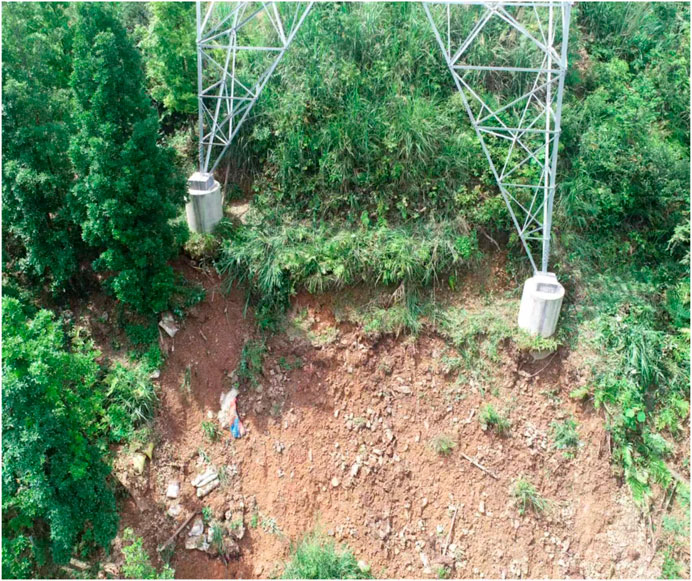
FIGURE 1. Potential geo-hazard of the pile foundation of a transmission tower built near a slope in Baise city, Guangxi province of China (photograph from the investigation of authors).
A pioneering study mainly focuses on single piles subjected to horizontal loading on level ground (Broms, 1964a; Broms, 1964b). Specifically, Broms (1964a, 1964b) developed an analytical formula of the ultimate soil resistance for laterally loaded flexible and rigid piles. Meyerhof (1995) developed a theoretical formula for predicting the ultimate soil resistance and bending moment of single piles under various load eccentricities and pile inclinations. In recent years, plenty of methods have been developed to predict the lateral response of single piles near slopes. The p–y method was originally developed by Matlock (1970) and Reese et al. (1974) for analyses of laterally loaded single piles, where p represents the soil reaction and y the lateral displacement of piles. Recently, some p–y curves consider the effect of a slope on the lateral response of single piles (Georgiadis and Georgiadis, 2012; Said et al., 2020). However, the p–y method neglects the soil continuity and the soil shearing resistance (Xu et al., 2013; Xu et al., 2017a; Xu et al., 2017b). To overcome this limitation, a strain wedge model was initially developed by Norris (1986). The strain wedge (SW) model predicts the soil resistance in the passive wedge developed in front of the laterally loaded pile by introducing a stress–strain relationship for the soils in the wedge. Recently, the SW model has been extensively modified to calculate the lateral soil resistance for single piles on level ground (Xu et al., 2013; Xu et al., 2017a; Xu et al., 2017b) and in the sloping ground (Peng et al., 2019; Yang et al., 2019; Chen et al., 2021; Chen et al., 2022; Lin et al., 2022a; Hemel et al., 2022). However, the application of the SW model to obtain the failure envelope of the bearing capacities of single piles is not reported. Thus, the 3D finite element method has an advantage of considering the 3D non-linear soil–pile interaction and thus is frequently applied to estimate the lateral response of pile foundations. Accordingly, Hung and Kim (2014) and Li et al. (2014) investigated the three-dimensional failure envelope through radial displacement and sliding tests as a means to assess the safety of the pile–soil system.
The influence of a slope on the bearing capacity of piles subjected to horizontal loading has been investigated via either a model test or numerical test. Begum and Muthukkumaran (2009) and Perumalsamy and Ranganathan (2022) experimentally investigated the influence of the slope angle and the relative density of soils on laterally single piles. The results indicated that these two factors have a significant influence on the lateral response of single piles. In addition, recent studies experimentally investigate other influential factors, such as the embedment depth of piles, the adhesion at the pile–soil interface, the pile length, and the distance (dpc) from the pile to the crest of the slope (Georgiadis et al., 2013; Deendayal et al., 2016; Vali et al., 2019). To supplement model tests, numerical analyses are conducted on laterally loaded piles in sloping ground. For example, Lin et al. (2022b) investigated the effect of various slope factors, e.g., the slope height, the slope angle, and dpc on the deflection and maximum bending moment of piles. Moreover, Jiang et al. (2018) studied the influence of the loading direction on the lateral response of single piles in sloping ground via the 3D finite element model. Jiang et al. (2020) further numerically investigated the effect of the slope proximity and pile shape on the deflection and the bending moment of laterally loaded piles. Previous studies show that the diameter and the embedment of piles also significantly affect not only the bearing capacity but also the lateral deflection and bending moment of laterally loaded piles (Muthukkumaran and Almas, 2011; Sawant and Shukla, 2014; Rathod et al., 2019; Chandaluri and Sawant, 2020; Deendayal et al., 2020). However, little work has been carried out on the influence of the slope on the failure envelope of bearing capacities of single piles near slopes, especially under combined HM loading.
This study conducted 3D finite element analyses of single piles in homogeneous sandy soils near slopes under combined HM loading. The 3D finite element model was calibrated against a model test reported by Chae et al. (2004). A parametric study was performed to obtain the failure envelope of bearing capacities of single piles under various combinations of H and M. The effects of the slope and dpc on the failure envelope were discussed. Moreover, a formulation was proposed to describe the failure envelope of bearing capacities of single piles.
2 Numerical modeling
2.1 Description of model tests
Figure 2 shows the model test conducted on a single pile near a slope. The model test was reported by Chae et al. (2004) where the single pile was located near a sandy slope with a slope angle of 30°. The pile was a hollow steel pipe pile with an outer diameter (D) of 100 mm and a wall thickness of 3 mm. The pile was loaded horizontally with a lateral load H in the dip direction of the slope. The distance between the lateral load and the mudline was 100 mm. The embedment depth of the pile was 500 mm.
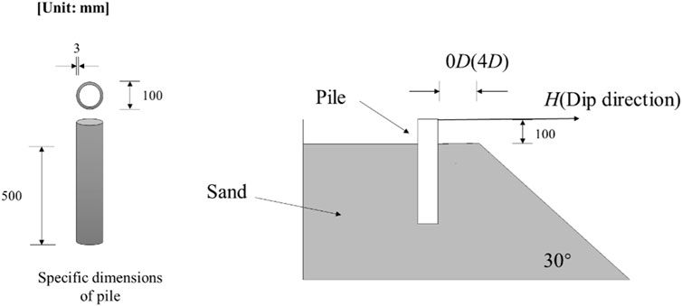
FIGURE 2. Setup of the model test on laterally loaded piles [adapted from Chae et al. (2004)].
Figure 3 shows a typical symmetric 3D finite element mesh using Abaqus was used for analyzing laterally loaded single piles near the sandy slope. dpc was 0D in this case. The single pile and the soil were modeled by C3D8R elements. The pile was assumed to behave elastically. The pile–soil interface was modeled by thin frictional elements (see Figure 3B), as suggested by Xu et al. (2023). C3D8R elements were also used for the pile–soil interface. The elastic–plastic behavior of sandy soil was described by the Mohr–Coulomb model. Table 1 lists the input parameters for the pile, the soil, and the interface. Based on triaxial compression tests of the sandy soil, the peak friction angle
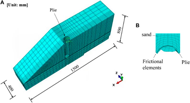
FIGURE 3. Symmetric 3D finite element model of the single pile near a sandy slope: (A) overall model; (B) the pile–soil interface modeled by frictional elements.
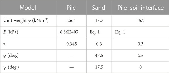
TABLE 1. Input parameters for the pile–soil system.
where E0 = 1,143 kPa,
The base and two lateral sides were fixed in the numerical analyses. Moreover, geostatic analysis was necessary for the slope before the lateral load was applied.
2.2 Model verification
Figure 4 shows the comparisons between simulated and the measured load–displacement curves. It should be noted that the lateral displacement was measured at the location where the lateral load was applied. The results showed that the simulated load–displacement curve agreed well with that measured from the test, demonstrating a sufficient accuracy of the proposed 3D numerical model. Accordingly, the proposed numerical model was considered a benchmark model for the following section.
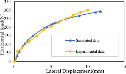
FIGURE 4. Comparisons between simulated and the measured load–displacement curves (experimental data from Chae et al., 2004).
3 Results and discussion
The sign convention for each direction at the top of the pile is defined in Figure 5. The positive x-axis is the dip direction of the slope. The horizontal force (H) applied in the dip direction was considered to be positive, and the bending moment (M) that forced the top of the pile to move in the dip direction was assumed to be negative.
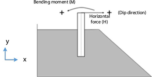
FIGURE 5. Sign definition for the bending moment and horizontal force.
To numerically obtain the failure envelope of bearing capacities of the single pile, both horizontal (h) and rotational (θ) displacements were applied simultaneously to the mudline, i.e., the ground surface. Moreover, the ratio of the horizontal displacement increase to the rotational displacement increase was kept constant, i.e., dh/Ddθ = constant. If the pile reached the ultimate state, divergence of the finite element analyses occurred, and then, bearing capacities (H0, M0) were defined as the last point of the load path in the HM plane (Gottardi et al., 1999). By varying the constant dh/Ddθ, the failure envelope of bearing capacities of single piles was obtained.
3.1 Failure envelope of bearing capacities of piles under combined HM loading near slopes
Taking the model in Figure 3 as a benchmark model (dpc = 0D), Figure 6A shows the calculated loading paths of single piles under different constants of dh/Dd
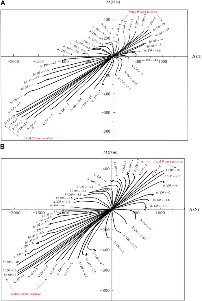
FIGURE 6. Effect of dpc on the bearing capacities of loading paths of laterally loaded single piles: (A) dpc = 0D and (B) dpc = 4D under different constants of dh/Dd
Moreover, the maximum distance (dmax) between the bearing capacity (H0, M0) and the origin (0, 0) was achieved at positive dh/Dd
From the results shown in Figure 6A, not only the slope but also the different HM combinations significantly affected the bearing capacity of single piles. Therefore, the most unfavorable condition should be considered in the engineering design.
3.2 Effect of the distance (dpc) from the pile to the crest of the slope
To investigate the influence of dpc on the bearing capacity of piles, another parallel 3D finite element model was analyzed and is shown in Figure 6. dpc in this model was 4D, i.e., 400 mm. To eliminate the boundary effect, one side of the model was extended 400 mm outwards (see Figure 7). In the parallel model, input parameters were kept unchanged from the model shown in Figure 3A.
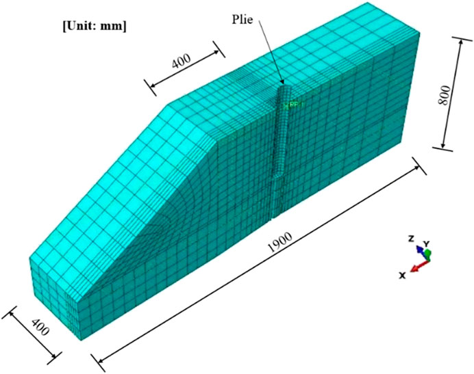
FIGURE 7. Symmetric 3D numerical model for a single pile with dpc = 4D.
Figure 6B shows loading paths of single piles with dpc = 4D under different constants of dh/Dd
3.3 Theoretical analysis of the failure envelope of bearing capacities of single piles in the HM plane
From the results shown in Figure 6, the failure envelope of bearing capacities of single piles showed an oblique ellipse in the HM plane. To verify this observation, a general elliptical equation was used to fit the data shown in Figure 6:
where x represents M0 in the HM plane; y denotes the H0 in the HM plane; and C1, C2, C3, C4, and C5 are the constants controlling the elliptical shape. A program was developed to derive the constants from the data based on the least square method. These six constants were used to determine the coordinates of the center of the ellipse (x0, y0), the width and height of the ellipses R1 and R2, and the rotation angle of the semi-major axis
Figures 8A, B show the failure envelope of bearing capacities of single piles near slopes for the cases with dpc = 0D and dpc = 4D, respectively. It should be noted that Figure 8 was determined by collecting the last point of loading paths in Figure 6. The relationship between the horizontal load and the bending moment data can be well-described by an oblique ellipse. Table 2 gives the fitting parameters of Eq. 2. Unlike the ellipse for single piles in the level ground reported by Li et al. (2014), the center of the ellipse was not at the origin but was located in the third quadrant due to the slope effect.
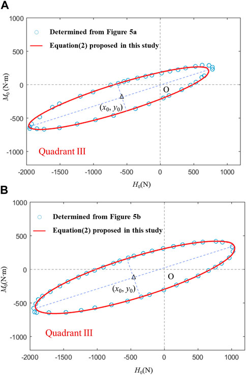
FIGURE 8. Failure envelope of bearing capacities of single piles near slopes: (A) dpc = 0D and (B) dpc = 4D.
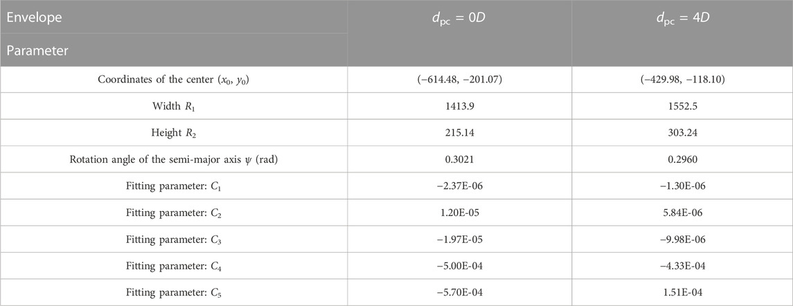
TABLE 2. Fitting results for the failure envelope of bearing capacities of single piles near slopes.
Table 2 also shows that the height R1 and the width R2 of the failure envelope increased by 9.8% and 40.9%, respectively, as dpc increased from 0D to 4D. In addition, the center of the failure envelope was much closer to the origin in the case of dpc = 4D. Thus, the center of the ellipse was approaching the origin and the oblique ellipse became bigger as dpc increased.
4 Conclusion
A 3D numerical model was proposed to accurately capture the non-linear pile–soil interaction in sloping ground and was calibrated against a model test. The conclusions are summarized as follows:
(1) The load–displacement curve simulated by the numerical model agreed well with the measured result, indicating a sufficient accuracy of the proposed 3D finite element model.
(2) An oblique ellipse can still be used to describe the failure envelope of bearing capacities of single piles near slopes in the HM plane. However, unlike the piles in the horizontal ground, the center of the envelope is not at the origin for piles in the sloping ground.
(3) The existence of slopes significantly reduced the bearing capacity of piles. On the other hand, the different combinations of H and M had also severely influence the bearing capacity of piles. Therefore, the most unfavorable condition should be considered in the engineering design.
(4) Increasing dpc had an insignificant effect on the maximum bearing capacity of piles but could significantly increase the bearing capacity under certain loading conditions, e.g., the minimum bearing capacity.
(5) The center of the ellipse was approaching the origin, and the oblique ellipse became bigger as dpc increased from 0D to 4D.
Data availability statement
The raw data supporting the conclusion of this article will be made available by the authors, without undue reservation.
Author contributions
MB: conceptualization, software, validation, and writing—original draft; JP and XZ: methodology; JL: investigation; SQ: data curation.
Funding
The authors declare that this study received funding from Electric Power Research Institute of Guangxi Power Grid Co. Ltd. of China (Grant number: GXKJXM20210299). The funder was not involved in the study design, collection, analysis, interpretation of data, the writing of this article, or the decision to submit it for publication.
Conflict of interest
Authors MB, JP, XZ, JL, and SQ were employed by the Electric Power Research Institute of Guangxi Power Grid Co., Ltd.
Publisher’s note
All claims expressed in this article are solely those of the authors and do not necessarily represent those of their affiliated organizations, or those of the publisher, the editors, and the reviewers. Any product that may be evaluated in this article, or claim that may be made by its manufacturer, is not guaranteed or endorsed by the publisher.
References
Begum, N., and Muthukkumaran, K. (2009). Experimental investigation on single model pile in sloping ground under lateral load. Int. Int. J. Geotech. Eng. 3, 133–146. doi:10.3328/IJGE.2009.03.01.133-146
Broms, B. (1964b). Lateral resistance of piles in cohesionless soils. J Soil Mech. Found. Div 90, 123–156. doi:10.1061/jsfeaq.0002132
Broms, B. (1964a). Lateral resistance of piles in cohesive soils. J Soil Mech. Found. Div 90, 27–63. doi:10.1061/JSFEAQ.0000611
Chae, K. S., Ugai, K., and Wakai, A. (2004). Lateral resistance of short single piles and pile groups located near slopes. Int. J. Geomech. 4, 93–103. doi:10.1061/(asce)1532-3641(2004)4:2(93)
Chandaluri, V. K., and Sawant, V. A. (2020). Influence of sloping ground on lateral load capacity of single piles in clayey soil. Int. J. Geotech. Eng. 14, 353–360. doi:10.1080/19386362.2017.1419538
Chen, L., Jiang, C., Pang, L., and Liu, P. (2021). Lateral soil resistance of rigid pile in cohesionless soil on slope. Comput. Geotech. 135, 104163. doi:10.1016/j.compgeo.2021.104163
Chen, L., Pang, L., Jiang, C., and Zhang, C. (2022). Analysis method for bearing capacity of laterally loaded rigid piles on slopes using improved failure wedge model. Comput. Geotech. 145, 104700. doi:10.1016/j.compgeo.2022.104700
Deendayal, R., Muthukkumaran, K., and Sitharam, T. G. (2020). Analysis of laterally loaded group of piles located on sloping ground. Int. J. Geomech. Eng. 14, 580–588. doi:10.1080/19386362.2018.1448521
Deendayal, R., Muthukkumaran, K., and Sitharam, T. G. (2016). Response of laterally loaded pile in soft clay on sloping ground. Int. J. Geotech. Eng. 10, 10–22. doi:10.1179/1939787915Y.0000000013
Georgiadis, K., Georgiadis, M., and Anagnostopoulos, C. (2013). Lateral bearing capacity of rigid piles near clay slopes. Soils Found. 53, 144–154. doi:10.1016/j.sandf.2012.12.010
Georgiadis, K., and Georgiadis, M. (2012). Development of p–y curves for undrained response of piles near slopes. Comput. Geotech. 40, 53–61. doi:10.1016/j.compgeo.2011.09.005
Gottardi, G., Houlsby, G. T., and Butterfield, R. (1999). Plastic response of circular footings on sand under general planar loading. Géotechnique. 49, 453–469. doi:10.1680/geot.1999.49.4.453
Hemel, M. J., Korff, M., and Peters, D. J. (2022). Analytical model for laterally loaded pile groups in layered sloping soil. Mar. Struc 84, 103229. doi:10.1016/j.marstruc.2022.103229
Hung, L. C., and Kim, S. R. (2014). Evaluation of undrained bearing capacities of bucket foundations under combined loads. Mar. Georesour. Geotec. 32, 76–92. doi:10.1080/1064119X.2012.735346
Jiang, C., He, J. L., Liu, L., and Sun, B. W. (2018). Effect of loading direction and slope on laterally loaded pile in sloping ground. Adv. Civ. Eng. 1-12, 1–12. doi:10.1155/2018/7569578
Jiang, C., Liu, L., He, J. L., and Xie, H. S. (2020). Effect of the proximity of slope and pile shape on lateral capacity of piles in clay slopes. Eur. J. Environ. Civ. Eng. 1-15, 16–30. doi:10.1080/19648189.2020.1858452
Jiang, J. H., Huang, X. L., Shu, X. R., Ning, X., Qu, Y., and Xiong, W. L. (2022). Application of a damage constitutive model to pile–slope stability analysis. Front. Mater 9, 1082292. doi:10.3389/fmats.2022.1082292
Li, Z., Kotronis, P., and Escoffier, S. (2014). Numerical study of the 3D failure envelope of a single pile in sand. Comput. Geotech. 62, 11–26. doi:10.1016/j.compgeo.2014.06.004
Lin, M., Jiang, C., Chen, Z., Liu, P., and Pang, L. (2022a). A method for calculating lateral response of offshore rigid monopile in sand under slope effect. Ocean. Eng. 259, 111812. doi:10.1016/j.oceaneng.2022.111812
Lin, M., Jiang, C., Liu, P., and Pang, L. (2022b). Analysis of laterally loaded offshore pile near slope in sand considering slope height. Ocean. Eng. 263, 112436. doi:10.1016/j.oceaneng.2022.112436
Matlock, H. (1970). “Correlations for design of laterally loaded piles in soft clay,” in Offshore Technology Conference, 577–594. doi:10.4043/1204-MS
Meyerhof, G. G. (1995). Behaviour of pile foundations under special loading conditions: 1994 R.M. Hardy keynote address. Can. Geotech. 32, 204–222. doi:10.1139/t95-024
Muthukkumaran, K., and Almas, B. N. (2011). Finite element analysis of laterally loaded piles on sloping ground. Indian Geotech. J. 41, 155–161.
Ng, C. W. W., and Zhang, L. M. (2001). Three-dimensional analysis of performance of laterally loaded sleeved piles in sloping ground. J. Geotech. Geoenviron. 127, 499–509. doi:10.1061/(asce)1090-0241(2001)127:6(499)
Norris, G. (1986). “Theoretically based BEF laterally loaded pile analysis,” in International Conference on Numerical Methods in Offshore Piling, 361–386.
Peng, W., Zhao, M., Xiao, Y., Yang, C., and Zhao, H. (2019). Analysis of laterally loaded piles in sloping ground using a modified strain wedge model. Comput. Geotech. 107, 163–175. doi:10.1016/j.compgeo.2018.12.007
Perumalsamy, K., and Ranganathan, S. (2022). Single pile in cohesionless soil in sloping ground under lateral loading. Int. J. Geotech. Eng. 13, 8. doi:10.1186/s40703-022-00173-8
Qu, C. X., Yi, T. H., Li, H. N., and Chen, B. (2018a). Closely spaced modes identification through modified frequency domain decomposition. Measurement 128, 388–392. doi:10.1016/j.measurement.2018.07.006
Qu, C. X., Yi, T. H., and Li, H. N. (2019). Mode identification by eigensystem realization algorithm through virtual frequency response function. Struct. Control Hlth. 26, e2429. doi:10.1002/stc.2429
Qu, C. X., Yi, T. H., Zhou, Y. Z., Li, H. N., and Zhang, Y. F. (2018b). Frequency identification of practical bridges through higher order spectrum. J. Aerosp. Eng. 31, 04018018. doi:10.1061/(ASCE)AS.1943-5525.0000840
Raj, D., Singh, Y., and Kaynia, A. M. (2019). V–H–M seismic capacity envelopes of strip foundations on slopes for capacity design of structure-foundation system. B. Earthq. Eng. 17, 2963–2987. doi:10.1007/s10518-019-00577-5
Rathod, D., Muthukkumaran, K., and Thallak, S. G. (2019). Experimental investigation on behavior of a laterally loaded single pile located on sloping ground. Int. J. Geomech. 19, 04019021. doi:10.1061/(asce)gm.1943-5622.0001381
Reese, L. C., Cox, W. R., and Koop, F. D. (1974). “Analysis of laterally loaded piles in sand,” in Offshore Technology Conference, 473–483. doi:10.4043/2080-MS
Said, S. E., Fayed, A. L., and El M, Y. (2020). P–y curves of laterally loaded piles near Earth slopes. Int. J. Eng. Adv. Technol. 9, 805–814. doi:10.35940/ijeat.D7763.049420
Sawant, V. A., and Shukla, S. K. (2014). Effect of edge distance from the slope crest on the response of a laterally loaded pile in sloping ground. Geotech. Geol. Eng. 32, 197–204. doi:10.1007/s10706-013-9694-7
Tatsuoka, F. (1993). “Relationships between stress and strain increments,” in Intr. to Strength of Soils and Failure of Ground, 57–81.
Vali, R., Shams, G., Porhoseini, R., Boroujeni, M. S., and Beygi, M. (2019). Lateral behavior of pile located on top of a slope. Aust. Geomech. J. 54, 103–114.
Wakai, A., Gose, S., and Ugai, K. (1999). 3-D elasto-plastic finite element analyses of pile foundations subjected to lateral loading. Soils Found. 39, 97–111. doi:10.3208/sandf.39.97
Xu, L. Y., Cai, F., Wang, G. X., Chen, G. X., and Li, Y. Y. (2017b). Nonlinear analysis of single reinforced concrete piles subjected to lateral loading. KSCE J. Civ. Eng. 21, 2622–2633. doi:10.1007/s12205-017-1010-2
Xu, L. Y., Cai, F., Wang, G. X., and Chen, G. X. (2017a). Nonlinear analysis of single laterally loaded piles in clays using modified strain wedge model. Int. J. Civ. Eng. 15, 895–906.
Xu, L. Y., Cai, F., Wang, G. X., and Ugai, K. (2013). Nonlinear analysis of laterally loaded single piles in sand using modified strain wedge model. Comput. Geotech. 51, 60–71. doi:10.1016/j.compgeo.2013.01.003
Xu, L. Y., Chen, W. Y., Cai, F., Song, Z., Pan, J. M., and Chen, G. X. (2023). Response of soil–pile–superstructure–quay wall system to lateral displacement under horizontal and vertical earthquake excitations. B. Earthq. Eng. 21, 1173–1202. doi:10.21203/rs.3.rs-1544907/v1
Xu, L. Y., Song, C. X., Chen, W. Y., Cai, F., Li, Y. Y., and Chen, G. X. (2021). Liquefaction-induced settlement of the pile group under vertical and horizontal ground motions. Soil Dyn. Earthq. Eng. 144, 106709. doi:10.1016/j.soildyn.2021.106709
Yang, M., Deng, B., and Wang, Y. (2019). A simplified calculation method for the near-slope laterally loaded pile based on a passive wedge model. Adv. Civ. Eng. 2019, 1–10. doi:10.1155/2019/8363252
Keywords: laterally loaded pile, slope, loading path, failure envelope, bearing capacity
Citation: Bian M, Peng J, Zhang X, Li J and Qin S (2023) Bearing capacities of single piles under combined HM loading near slopes. Front. Mater. 10:1180345. doi: 10.3389/fmats.2023.1180345
Received: 06 March 2023; Accepted: 17 March 2023;
Published: 19 April 2023.
Edited by:
Chun-Xu Qu, Dalian University of Technology, ChinaCopyright © 2023 Bian, Peng, Zhang, Li and Qin. This is an open-access article distributed under the terms of the Creative Commons Attribution License (CC BY). The use, distribution or reproduction in other forums is permitted, provided the original author(s) and the copyright owner(s) are credited and that the original publication in this journal is cited, in accordance with accepted academic practice. No use, distribution or reproduction is permitted which does not comply with these terms.
*Correspondence: Meihua Bian, Ymlhbl9taC5zeUBneC5jc2cuY24=, Z3hkd3htQDEyNi5jb20=