 C. Belei
 P. S. Effertz1
 B. Meier
 S. T. Amancio-Filho
- 1Institute of Material Science, Joining and Forming—BMK Endowed Professorship for Aviation, Graz University of Technology, Graz, Austria
- 2Joanneum Research—Materials, Graz, Austria
As-printed Laser-Powder Bed Fusion (LPBF) surfaces can provide anchoring spots for the infiltration of polymer printed by Fused Filament Fabrication (FFF), enhancing metal-polymer joint strength. This work evaluates the influence of the as-printed LPBF surface roughness and FFF parameters on the strength of Ti-6Al-4V/PA-CF joints produced by this process combination. A three-point bending testing method based on ISO 14679:1997 was deployed, whereby the energy dissipated by the joint interface was measured. Roughness was varied by 3D-printing the substrate with different inclination angles; Height and printing speed of the coating layer (the polymer layer in direct contact with the metal) were also varied. Data was interpreted using a combination between Decision Tree and Gradient Boosting Regression, ultimately suggesting that printing speed is the prominent parameter followed by inclination angle for joint strength. Additionally, the combined effect of low printing speed and inclination angle resulted in the highest energy absorption at the interface (>200 J).
1 Introduction
The Additive Manufacturing (AM) of polymers and metals—both extensively explored by researchers and industries nowadays—have mostly developed in separate ways. While both groups of AM processes share advantages (e.g., the production of complex near-net shape parts with low material waste (Ngo et al., 2018)), the processes themselves differ considerably, being this a natural consequence of the inherent discrepancies in terms of chemical composition, atomic arrangement and therefore processing requirements and material properties. On the one hand, metal AM normally requires a high energy density to melt the feedstock material due to their relatively high melting temperature ranges (Liu et al., 2018). On the other hand, polymer AM does not require the same levels of energy density. Thus, it can be performed by controlling the solidification (or consolidation when printing temperature is above glass transition temperature) of feedstock material that is liquefied beforehand (instead of melting/softening it locally, which is the case in metal AM).
Combining polymer and metal AM into a single process would allow for the production of fully additively-manufactured metal-polymer hybrid parts, enabling a greater designing freedom regarding not only part geometry, but also local and global properties. Such a combination is however an extremely challenging task, for the reasons mentioned earlier. Although processes such as SLS are capable of 3D-printing both metals and polymers (Papazoglou et al., 2022; Liu et al., 2007), merging those capabilities into a single print job to produce a metal-polymer hybrid joint is not trivial. A likely difficulty with this approach would be the handling of different powders, which would require a machine with separate powder dispensers and recoaters (Mehrpouya et al., 2022). One could also argue that SLS is not the most effective AM technique for neither metals nor polymers, since better alternatives are available, such as powder bed fusion and fused filament fabrication, respectively. Therefore, the production of metal and polymer parts could also be accomplished by separate AM processes, with the subsequent joining being done by a third, non-AM process, such as adhesive bonding, mechanical fastening or friction-based techniques (Amancio-Filho and Blaga, 2018; Lambiase et al., 2021; Carvalho and Amancio-Filho, 2022).
Such an alternative, however, can be further optimized by reducing manufacturing steps, specifically the third one (i.e., metal-polymer joining). The use of Fused Filament Fabrication principles to 3D-print polymer/composite parts directly onto metallic substrates (thus skipping a later joining step) has been recently gaining momentum in the scientific community. A description of this approach (which in the present manuscript will be referred to as “AddJoining” (Filho and Falck, 2018)) is presented in Figures 1A. It has been proven feasible for a number of metal-polymer combinations, including AA2024-T3/CF-PA6 (R. Falck et al., 2018), AA2024-T3/ABS (Rielson et al., 2019), AA6082-T6/PLA (Bechtel et al., 2020), AA5052/PLA (Alhmoudi et al., 2022), AA6082-T6/PETG (Bechtel et al., 2022), AA5754/PP (Hertle et al., 2020), Ti-4Al-4V/PA-CF (Belei et al., 2022a), SS 316L/PLA and PET (Chueh et al., 2020), AlSi10Mg/PLA (Englert et al., 2022) and PC (Oliveira et al., 2023), among others.
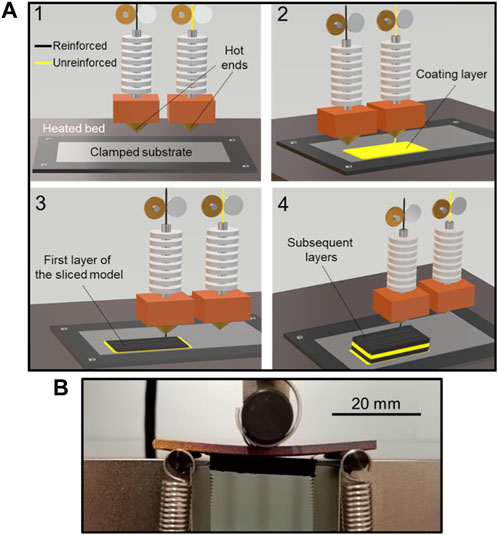
FIGURE 1. (A) Schematics of the AddJoining approach based on a three-axis 3D-printer and a generic material combination. (1) A flat substrate is clamped onto a heated bed, while a dual extrusion system is loaded with unreinforced and reinforced filaments; (2) a layer of unreinforced polymer is deposited in direct contact with the substrate (“coating layer”); (3) the first layer of the sliced model is deposited over the coating layer; (4) the subsequent layers of the model are 3D-printed following FFF principles. Adapted from (Belei et al., 2022a) with permission; (B) Three-pointing bending test of a Ti-6Al-4V/PA-CF hybrid joint.
The latter study of this list, by Chueh et al. (2020), explored for the first time the use of Laser-Powder Bed Fusion (LPBF) SS 316L parts as substrates for the AddJoining. In that study, the authors proposed the use of specially-designed surfaces with well-defined cavities in the millimeter scale, onto which the polymer model (PLA and PET) would be subsequently 3D-printed. Those cavities ensured that a satisfactory anchoring between metal and polymer would be achieved, enhancing the joint strength both under shear and tensile loading. This was realized using a custom-made, multi-material 3D setup, which integrated the LPBF and FFF stages into a single print job. In the near future, alternatives such as the one introduced by (Chueh et al., 2020) may be proven feasible in the large scale production of metal-polymer hybrid parts by AM. Later on, Englert et al. (2022) and Oliveira et al. (2023) reproduced a similar idea, with a different substrate material (AlSi10Mg) and increased variety of surface designs and sub-milimetric micro-anchoring features (e.g., gecko-like micro-pillars), achieving satisfactory results in terms of quasi-static mechanical strength.
Based on those particular studies, it would be worth considering that, before anything else, as-printed LPBF parts tend to already have a relatively high surface roughness (Yadollahi et al., 2017; Koutiri et al., 2018; Skalon et al., 2020; Lizzul et al., 2021; Pérez-Ruiz et al., 2022; Simson and Subbu, 2022), being this feature most likely a positive trait for the AddJoining approach. Studies in the past resorted to a number of different strategies to make metallic surfaces more susceptible to metal-polymer interlocking, such as sandblasting (Falck et al., 2019; Hertle et al., 2020; Belei et al., 2022a) and CNC machining (Alhmoudi et al., 2022). Theoretically, those strategies would not be necessary for as-printed LPBF substrates, since their inherently rough surfaces may already provide enough anchoring sites for metal-polymer interlocking. If this is indeed the case, one could save time and energy by forgoing both surface finishing steps and also the implementation of special surface features for improved mechanical interlocking (such as the ones in (Chueh et al., 2020; Englert et al., 2022)), since those in particular could be rendered redundant.
Normally, the bond strength in these cases is evaluated using single lap-shear tests. This is a well-known and widely used approach (Falck et al., 2018; Falck et al., 2019; Bechtel et al., 2022; Belei et al., 2022a; Oliveira et al., 2023) that can be used as a powerful benchmarking tool to evaluate the performance of joints produced under different circumstances. Additionally, this test also provides information regarding the behavior of the joint when exposed to a mix between fracture modes I and II. As such, however, it does not necessarily provide a complete picture of the interfacial strength, which can be assessed using other loading conditions as well (Genty et al., 2017). An alternative is the three-point bending test based on ISO 14679:1997 (Roche et al., 1982; Genty et al., 2017; Birro et al., 2021; Belei et al., 2022a), which consists of measuring the force necessary to bend a metallic substrate until the detachment of an adhesive block that was previously adhered to it. Based on the force x displacement curve, the energy absorbed by the adhesive/composite part during the test can also be calculated. An example of such a test being performed is shown in Figures 1B. In comparison to the single-lap shear, this test offers the advantage that the fracture mode can be mostly considered mode I, as opposed to a mix of I/II (Genty et al., 2017). Since it assesses the joint strength from a different perspective, one cannot expect that satisfactory results in lap shear tests would readily be translated into a high performance under bending and vice versa, as proven by (Belei et al., 2022a). In that situation, optimized conditions required about 4 kN to fail on shear tests, but only around 5% of this value for the interface detachment during three-point bending. Finally, another advantage of the three-point bending test is that it requires smaller specimens, which saves time and material resources, thus allowing for a more efficient strength assessment.
Utilizing the three-point bending test as an evaluation tool, the objective of the present study is to explore the relationship between as-printed LPBF surface roughness and joint strength on metal-polymer hybrid parts manufactured by the AddJoining approach. In the present case, a combination of LPBF Ti-6Al-4V, polyamide 6/66 and a short carbon reinforced polyamide-based polymer was used. In order to evaluate different joining scenarios, surface roughness was varied by 3D-printing the substrate with several different inclination angles, which resulted in different roughness levels on the downskin surface (DS). Additionally, process parameters for the AddJoining approach were also varied, namely, the printing speed of the “coating layer” (i.e., the first polymer layer in direct contact with the metal substrate) and also its height. The present study concluded that not only as-printed LPBF surfaces enabled satisfactory levels of metal-polymer interlocking, but also that the rougher those surfaces were, the higher the ensuing joint strength tended to be.
2 Materials and methods
2.1 Materials
2.1.1 Metallic powder
Commercially available Ti-6Al-4V (Grade 5) powder was used to 3D-print the metallic substrates by LPBF (see Section 2.2.1). Its chemical composition (virgin) consisted of the following: 6.13 wt.% Al, 3.90 wt.% V, 0.16 wt.% O, 0.0281 wt.% N, 0.01 wt.% C, 0.07 wt.% Fe, 1.1 ppm Ar, 21 ppm H and balance of Ti (Meier et al., 2022a; Meier et al., 2022b). Particle size distribution and sphericity were measured in accordance with ISO 13322-2 by Dynamic Image Analysis carried out with a Retsch CAMSIZER XT optical particle analyzer (Germany). Particle size distribution were measured as follows: D10 = 18.8 µm; D50 = 33.6 µm; D90 = 48.7 µm. Sphericity: W/H = 0.89; bh13 = 0.94.
2.1.2 Polymer/composite filaments
For the manufacturing of each specimen, two different thermoplastic materials were used: one for the coating layer only and another for the subsequent layers. The coating layer material consisted of Polyamide 6/66, supplied in a filament form (ø 2.85 mm) by Ultimaker (Netherlands). Glass transition temperature (Tg), melting onset (Tonset) and melting peak (Tm) were measured by (Belei et al., 2022a) at 50°C, 167°C and 190°C, respectively. Melt mass flow rate (MFR) of 6.2 g/10 min was measured by the supplier based on ISO 1133, at 250°C and with a load of 1.2 kg (Ultimaker Nylon TDS, 2023).
As for the subsequent layers, a commercial-grade polyamide reinforced with short carbon fibers was used, also in filament form (ø 2.85 mm), being supplied by BASF (Netherlands). Fiber volume fraction was 6.5% ± 0.2%, while fiber length and diameter 136.2 ± 83.0 μm and 5.6 ± 1.0 μm, respectively. Tg, Tonset, and Tm were measured by (Belei et al., 2022a) at 67°C, 203°C and 237°C, respectively. MFR at 275°C and 5 kg was measured by the supplier based on ISO 1133, registering a value of 51.9 g/10 min (Ultrafuse® PAHT CF15, 2023).
2.2 Manufacturing
2.2.1 Laser-Powder Bed Fusion
Ti-6Al-4V plates (see dimensions in Figures 2A) were 3D-printed by Laser Powder Bed Fusion using an EOS 280 printer (Germany) equipped with a 400 W laser (wavelength of 1,064 nm). Process parameters were kept constant, with a laser power of 280 W, a scan speed of 1,200 mm/s, a hatching distance of 140 µm and a layer thickness of 30 µm. The inclination angle θ in relation to the platform was varied between 40° and 90° in multiples of ten, for a total of six different θ values. No support structures were used. After the process, the 3D-printed substrates were stress relieved for 2 h at 650°C (heating and cooling rates of 30 K/min and 5 K/min, respectively). Parameters for both the process and the stress relieving were obtained based on (Meier et al., 2022a).
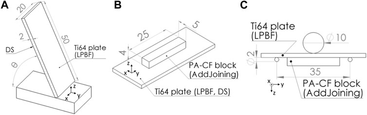
FIGURE 2. (A) Schematics of the Ti-6Al-4V substrates printed by L-PBF. Z denotes the build direction; (B) Schematics of the PA-CF block 3D-printed on L-PBF substrates using the AddJoining approach. Z denotes the build direction; (C) Schematics of the three-point bending test, based on ISO 14679:1997. Ti64 denotes Ti-6Al-4V. Dimensions in mm.
2.2.2 AddJoining
The 3D-printing of the polymer part on the metallic substrate (AddJoining) was carried out in an Ultimaker S5 FFF printer (Netherlands). Before proceeding with the AddJoining stage, the substrates were cleaned with an ultrasonic bath for 15 min using water, then rinsed with acetone.
The substrates were then fixed to the print bed using a sample holder originally designed to produce single-lap joints (Belei et al., 2022a), with the schematics presented in Figure 3. The DS of the substrate was positioned facing upwards, being therefore the surface on which the polymer was deposited. Masking tapes (3M Scotch Tape, United States) were applied on both substrate extremities to increase its stability during the polymer deposition.
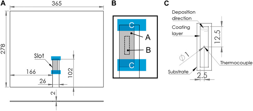
FIGURE 3. (A) Adapted printing platform implemented for the AddJoining experiments; (B) Close-up on the substrate placement. A represents the substrate, B the area where the PA-CF block was printed and C strips of masking tape for improved stability; (C) Schematics of the thermocouple placement (top view). Dimensions in mm.
The polymer part 3D-printed on the metallic substrate consisted of a 25 × 5 × 4 mm block, positioned on the center of the substrate as showed in Figure 2B. This block was printed in two stages. First, one layer of the unreinforced polyamide 6/66 was deposited directly onto the metallic substrate (coating layer). In this stage, process parameters (printing speed v and layer height h, see Table 1), as well as the substrate inclination angle θ (Figure 2A) were varied based on a 3k full-factorial design of experiments; however, since θ had six levels (instead of three levels, which as the case for the other two factors), the experimental matrix tallied 54 unique conditions. Three replicas per condition were produced.
Next, following the deposition of the coating layer, subsequent layers of the PA-CF block (“composite part”) were printed with the reinforced polyamide, using constant process parameters for every condition (Table 1). Those parameters were obtained based on a previous optimization study (Belei et al., 2022b).
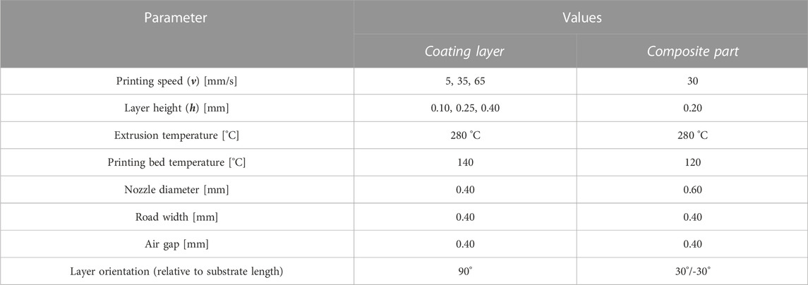
TABLE 1. Process parameters for the AddJoining approach.
Finally, for some pre-determined conditions (v = 5, 35 and 65 mm/s; h = 0.4 mm; θ = 90°), the temperature at the metal-polymer interface during the coating layer deposition was recorded using a type K thermocouple inserted from underneath the substrate through a hole drilled on it (Figure 3C). The acquisition rate was 300 Hz. Specimens used during temperature measurements were not mechanically tested afterwards.
The pre-determined conditions mentioned earlier were selected as such in order to enable a direct comparison with the temperature measurements reported by (Belei et al., 2022a). By that time, the authors kept h constant at 0.4 mm since this was the value that resulted in the highest joint strength (via single-lap shear tests). Additionally, the inclination angle θ (variable absent in (Belei et al., 2022a)) was kept at 90° for the present study, since this was the value resulting in the closest surface roughness (see Section 3.1) in comparison to (Belei et al., 2022a).
2.3 Three-point bending test
Joints were tested with an adapted three-point bending test based on the ISO 14679:1997, with a setup presented in Figures 2C. The test was performed on a Shimadzu AGS-X (Japan), equipped with a loading cell of 5 kN, carried out with a traverse speed of 0.5 mm/min. Force and displacement were registered at a frequency of 100 Hz. Other than the Force x Displacement curve, the force at which the block detached from the substrate (critical force, Fc) was also recorded. The critical force Fc was identified on the Force x Displacement curve as the earliest point at which the derivative of the Force with respect to the Displacement assumed negative values. This represented a loss in stiffness of the system as a result of the block detachment (Roche et al., 1982; Sauvage et al., 2017; Birro et al., 2021; Belei et al., 2022b). However, as latter explained in Section 2.3, this stiffness loss was not always sharp enough to result in negative force derivatives; in those cases, Fc was defined by the point at which the force derivative assumed the lowest value.
Additionally, the three-point bending test was also conducted in substrates without blocks, as a means to evaluate the force at yield, as well as the slope of the Force x Displacement curve at the elastic region excluding the influence of the PA-CF block. Those measurements used the same experimental setup as mentioned earlier. The slope of the elastic region was calculating using points between 400 N and 500 N. The force at yield was inferred adopting the 0.2% offset method, commonly applied to determine the yield stress of metals based on uniaxial tensile tests (Ang et al., 2016; Benito et al., 2016; Hasemann et al., 2019). In the present case, the use of force (as in “force at yield”) instead of strength was chosen, as it facilitates a direct comparison with subsequent Fc values from metal-polymer specimens.
2.3.1 Assessment of the absorbed energy during three-point bending test
In this work, the effectiveness of a parameter combination on the joint strength was evaluated using an energy approach based on the work from Birro et al. (2021). This approach consisted in the following steps: (i) the total resilience of the substrate-block system up to the detachment (Wtotal) is calculated based on the integral of the Force x Displacement curve, (ii) the resilience expected for the substrate without the block (Wmetal) is calculated and then (iii) subtracted from Wtotal. The result is the resilience of the composite block (including the coating layer), which is represented by Wcomposite. The sequence is summarized by Figure 4. With this approach, it is possible to mitigate the influence of possible differences in substrate stiffness across different parameter combinations, which would affect a direct comparison using only Fc.
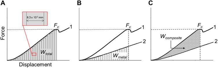
FIGURE 4. Summary of the sequence used for the calculation of Wtotal, based on (Birro et al., 2021). Step (A) integral of Force x Displacement curve for hybrid specimen (1) calculated up to Fc (Wtotal); Step (B) integral of average curve for standalone substrates (2) calculated up to Fc (Wmetal); Step (C) Wmetal is subtracted from Wtotal, resulting in Wcomposite, visualized as the area between curves 1 and 2.
For step (i), the area below the Force x Displacement curve for substrate-block hybrid joints was approximated by subdividing it into individual rectangles up to the displacement at Fc, see Figure 4A. The area from rectangles below 10 N were discarded. The total area (Wtotal) was equal to the sum of the areas of each rectangle. The width of the rectangles was equal to one displacement step, or 8.3 × 10⁻⁵ mm.
For step (ii), an approach similar to step (i) was implemented, this time using Force x Displacement curves from standalone, substrate-only specimens. Three different curves for each θ value where averaged, point by point, resulting in six individual curves. Then, for each hybrid joint condition, the area below the substrate-only curve (Wmetal) was calculated up to Fc (Figure 4B), with the corresponding substrate-only curve being selected depending on θ. Similar to step (i), the area from rectangles below 10 N were discarded. Finally, for step (iii) Wmetal was subtracted from Wtotal to obtain a Wcomposite (Figure 4C).
2.4 Surface roughness measurements
For each θ value, the DS of three distinct LPBF specimens (prior to AddJoining) had their average area surface roughness (Sa) measured using a Keyence VHX-6000 digital microscope (Germany). This resulted in a unique Sa average and standard deviation for each θ value. For the roughness measurements, an area of 5 mm × 5 mm was scanned, using a magnification of 100x. A Gaussian filter was applied on the initial results, using S = 25 µm and L = 2 µm.
2.5 Prediction modelling using Decision Tree Regression and ensemble methods
2.5.1 Decision Tree Regression
The Decision Tree Regression (DTR) algorithm generates, based on the input data set, a single decision tree which will predict a specific outcome dependent on various input parameters. In this case, generating a model means training a model with a certain training data set. Depending on the desired response, python builds a regression or classification decision tree following the, slightly changed, CART-algorithm (Classification And Regression Tree). With this algorithm, only binary trees can be built, meaning that at each node there are only two possible ways to go.
2.5.1.1 Decision Tree Regression—Mathematical formulation
Given training vectors
Subsequently, the impurity function or loss function
to which appropriate parameters should be selected to minimize the impurity, i.e.,:
In regression, since the label (target or response) is a continuous value, Mean Squared Error (MSE) was employed as the criteria to minimize the loss function
Where
This procedure is repeated until a certain number of splits is reached (i.e., maximum depth) or the number of samples in a node is 1 (
2.5.1.2 DTR statistical indicators
A coefficient of determination of 0.99 and 0.70 was obtained for the training and test set, respectively, with MSE at 244.49. The discrepancy in R2 between training and testing, with testing being significantly lower, implies the model clearly shows high variance, hence overfitting. Ultimately, DTR is not well suited to generalize for unseen data.
2.5.2 Ensemble methods
An ensemble is an approach that combines multiple algorithms into a single predictive model able to decrease bias and variance, and increase predictive ability. A single decision tree will rarely generalize well to data it was not trained on, as is the case described herein, due to the fact that “pure” decision trees display low bias and high variance. To overcome this, several decision trees can be combined to obtain accurate predictions, since averaging the result of many trees will reduce variance while maintain bias.
This work brings together not only application of ''pure'' DTR, but also a comparison with ensemble methods based on Decision Tree theory (Breiman et al., 1984), from which the best model was selected and scrutinized for the purposes of AddJoining performance optimization. Table 2 summarizes relevant statistical indicators obtained for the generated ensemble models. Even though each ensemble’s hyperparameters were optimized, a considerable amount of overfitting was observed for Random Forest, Extra Trees, Bagging and AdaBoost. Nonetheless, for all the aforementioned, MSE was reduced in comparison with DTR, which indicates the ensemble approach was effective in curtail bias. Contrastingly, Gradient Boosting Regression (GBR) exhibits very satisfactory
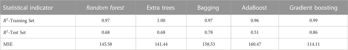
TABLE 2. Statistical evaluation of the studied regression ensemble models.
Since GBR proved to be the most reliable model, for the sake of completion, a more in-depth review over the mathematical details of this algorithm is provided in the upcoming sub-section.
2.5.2.1 Gradient Boosting Regression—Mathematical formulation
Gradient boosting Regression (GBR) is one of the variants of regression ensemble methods where multiple weak models are combined to achieve better overall performance. GBR is one of the most popular algorithms to handle tabular datasets, with the ability to find any nonlinear relationship between your model target and features and has great usability that can deal with missing values, outliers, and high cardinality categorical values on your features without any special treatment (Friedman, 2001).
The formulation of the GBR algorithm can be described according to the following pseudo-code (Friedman, 2001; Hastie et al., 2009).
1. Create an initial constant value prediction
where
Since the objective is to find the value
Performing the calculation yields that
2. Iteratively, from
i. Calculate the pseudo-residuals
The negative gradient is convenient to access the direction and magnitude in which the loss function can be minimized.
ii. Fit a base learner (or weak learner, e.g., tree) against the pseudo-residuals
iii. Compute
thus,
By computing Eq. (13), it can be concluded that the optimal
where
iv. Update the model:
2.5.3 Training, test and hyperparameter tuning
The Machine Learning (ML) endeavors realized herein, where performed using python programming language, with proper use of the relevant API’s (e.g., sklearn, numpy, pandas, etc.). To train a model that can adequately fit the data, but also generalizes well for “unseen” observations, a suitable train/test split must be specified. For this problem, due to the low amount of data available, a sensitivity analysis was conducted, from which a train/test split of 75% and 25% was considered, respectively, and partitioned in 6-fold-cross-validation. Additionally, the hyperparameters of each algorithm were tuned, using automated using “GridSearchCV” technique. This method creates a grid of hyperparameters of interest and their considered values, subsequently fitting models to every single combination of these parameters (Raschka and Mirjalili, 2019). An optimized set of parameters, regarding specific criterion (e.g., the lowest MSE or the highest
2.6 Microstructural characterization
Optical and Scanning Electron Microscopy (OM and SEM, respectively) were deployed during the present study. For OM, a Zeiss AX10 Observer Z1m optical microscope (Germany) in bright field mode was utilized; for SEM, a Tescan Mira-3 scanning microscope (Czech Republic), utilizing both secondary electron (SE) and backscattered electron (BSE) detectors. For fracture surfaces, specimens containing residual polymer where carbon sputtered prior to the SEM analysis, which was carried out with an acceleration voltage of 5 kV, a chamber pressure of 10-1 Pa and a work distance of 50 mm.
3 Results and discussion
3.1 Substrate characterization
The three-point bending test as proposed by Roche et al. (1982) is highly dependent on the substrate properties. For one, the detachment force is a result not only of the adhesive strength (which ultimately is the object of study of the test), but also of the substrate stiffness (Sauvage et al., 2017). Moreover, the test is conducted ideally within the elastic domain, meaning that the force at yield should be higher than the Fc range. Finally, besides the remarks related to mechanical properties of the substrates, their surface roughness also plays a role on the test outcome, since it is closely related to the effectiveness of micromechanical anchoring between metal and adhesive (in this case 3D-printed polymer) (Leeden and Frens, 2002; Zhang and Huang, 2021; Schmidt and Chen, 2022). Therefore, in order to obtain a better understanding of the substrate role on subsequent three-point bending tests, substrates from different θ values were evaluated both mechanically and in terms of roughness (see Section 2.3 and 2.4), with Figure 5 summarizing the results.
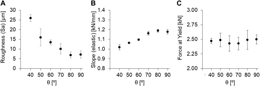
FIGURE 5. Results of the L-PBF Ti-6Al-4V substrate characterization with respect to the inclination angle θ. (A) Areal surface roughness, (B) slope of the Force x Displacement curve in the elastic region, (C) Force at yield.
These results reveal two different aspects that will later be relevant for the mechanical testing of hybrid joints. Firstly, it can be observed that the surface roughness is highly dependent on θ, with lower θ values resulting in rougher surfaces (Figure 5A). According to the literature (Covarrubias and Eshraghi, 2018; Ni et al., 2018; Melia et al., 2020; Skalon et al., 2020; Hofele et al., 2021), this can be attributed to the presence of partially molten particles, which during the LPBF process acted as a partial support for the melt pool at contour regions, remaining attached to the DS subsequently. As θ decreases, a greater melt pool area rests over loose particles, which leads to a higher quantity of such particles getting fused to the DS surface, effectively increasing its roughness. The melt pool can also flow downwards, causing protuberances to which surrounding powder can adhere as well (Charles et al., 2021; Feng et al., 2021). These effects can be visualized in Figure 6. Nonetheless, it is important to emphasize that, in this case, rough substrates result in more anchoring sites around which the polymer can flow during the AddJoining process, as previously discussed on Section 1. Consequently, θ may play a role on the hybrid joint strength; this remark will be discussed in further detail in the upcoming sections.
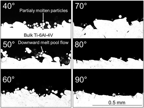
FIGURE 6. OM images of the DS from L-PBF Ti-6Al-4V specimens 3D-printed with different inclination angles.
Secondly, the analysis of the mechanical properties as a function of θ revealed a slight increase in stiffness (represented by the slope of the Force x Displacement curve in the elastic domain, Figure 5B) towards higher θ values. Although this trend could not be considered substantial (the difference between θ = 40° and θ = 90° was 16%), the result shows that a proper assessment of the joint strength across different processing conditions must compensate for the differences in stiffness as a function of θ, which is the case for the energy based approach (see Section 2.3.1), which factors out the portion of the resilience attributed to the metallic substrate, i.e., proportional to its stiffness (Sauvage et al., 2017). Lastly, the Force at Yield was relatively constant across different θ values, with an average hovering around 2.5 kN (Figure 5C). Later, this result will show that, during the three-point bending test, the PA-CF block detachment always occurred at a force Fc insufficient to cause plastic deformation on the substrate.
3.2 Hybrid joints characterization
3.2.1 General aspects of the three-point bending test
Two types of Force x Displacement curves could be identified. The criterion to differentiate both types was whether the derivative of the Force with respect to the Displacement ever assumed negative values; if so, that would represent a relatively sharp loss in stiffness as a result of the detachment of the polymer block. On the other hand, if that derivative never assumed negative values, that would mean that the loss in stiffness was smoother, being therefore harder to infer, from the curve, the moment at which the polymer block detached from the substrate. For the following discussion, the former case will be termed “sharp curve” and the latter “smooth curve”. A visual representation of those two types of curves can be seen in Figure 7.
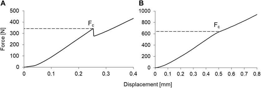
FIGURE 7. Representative Force x Displacement curves resulting from three-point bending tests. (A) Sharp transition; (B) Smooth transition. Process parameters: v = 5 mm/s, h = 0.25 mm, θ = 90° (A) and 60° (B).
The emergence of either type of curve, however, did not seem to be due to any special circumstance or combination of parameter. Table 3 summarizes the average values from parameters and responses for each curve type. Other than a slight tendency of having sharp curves on conditions with lower v, sharp curves also tended to appear in conditions with higher θ, that is, when the surface roughness was lower (see Figure 5A). In terms of responses (Fc and Wcomposite), no noticeable differences could be observed with respect to the average results. In either case, there was a high standard deviation on both responses, showing that a given curve could be sharp or smooth within a wide range of outcomes, i.e., both stronger and weaker joints could yield either type of curve. Furthermore, the frequency of occurrence from both curve types is virtually equal.
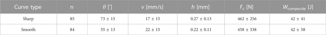
TABLE 3. Summary of the average process parameter values and responses for each curve type.
Those results suggest that the occurrence of a given curve type is mostly random. Other authors also suggested that a stepwise stiffness reduction might be a consequence of defects present at the interface, resulting in a more gradual crack propagation at the metal-polymer interface (Birro et al., 2021; Belei et al., 2022a). In the present case, the interface is highly irregular, containing not only defects such as entrapped air bubbles (as covered in Section 3.2.3), but also protuberances of irregular shapes and sizes (see Figure 6). Those may have affected the shape of the curve unpredictably.
However, it is also important to point out that the substrate thickness may have also played a role on this matter. A stepwise crack propagation on a thinner substrate would most likely reveal a curve with a distinct peak (Fc) followed by a gradual descent with several smaller peaks until the curve reached the substrate baseline. This was evidenced by (Belei et al., 2022a), which used rolled Ti-6Al-4V substrates with a thickness of 0.5 mm. On the other hand, since the substrates used on the present study were substantially thicker (2 mm), the substrate baseline was higher; thus, the visual features expected from a stepwise propagation curve were blended with the substrate baseline itself, resulting in a single smooth curve. Nevertheless, the use of thicker substrates in this case was justified, since they required a higher force to deform plastically. This ensured that the three-point testing of hybrid joints would be carried out entirely on the elastic domain, meaning that any deviation from the expected linear-elastic behavior could only stem from the presence of the PA-CF block, and not from any plastic strain on the substrate itself.
Lastly, it is important to emphasize that, despite the high scatter observed in the average responses across all conditions, the results of the statistical analysis revealed that process parameters did have a significant influence on both Fc and Wcomposite, see Table 4. By performing Analysis of Variance (ANOVA) using an α of 0.05, both θ and v were found to have a statistically significant effect, as indicated by their very low p-values and F above F-crit both with respect to Fc and Wcomposite. These findings suggest that despite the variability in the data, there are clear associations between the response variable and these parameters, which will be further discussed in the upcoming sections.
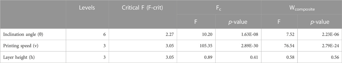
TABLE 4. ANOVA summary (α = 0.05) describing the statistical significance of each process parameter on both Fc and Wcomposite.
3.2.2 Prediction model
Valuable information can be drawn from the GBR model concerning the influence of parameters in the bending performance of AddJoined components. In terms of performance, the model achieved a coefficient of determination (R2) of 0.997 and 0.860 for the training and test sets, respectively, as already described in Table 2. Figure 8A provides visual intuition to those statistical indicators, highlighting the adequacy of GBR, as predicted Wcomposite values matched the actual experimental values. This hold true for both training and tests sets. Moreover, a validation set, consisting of five experiments each with distinct parameter sets, was used for the post hoc evaluation of the GBR model, revealing a satisfactory predicting ability.
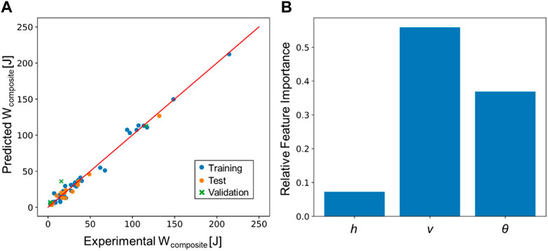
FIGURE 8. (A) Predicted vs. Experimental Wcomposite plot; (B) Relative feature importance based on the GBR model.
In terms of feature importance (Figure 8B), the printing speed v was considered the most influent parameter on the response Wcomposite, followed by the inclination angle θ and layer height h, respectively. This corroborates the results from the ANOVA presented earlier, but were the opposite of what has been observed in (Belei et al., 2022a). In that study, using Fc as a response, h was considered statistically significant while v was not. However, even in that case, a tendency indicating the average Fc being inversely proportional to v could be noticed. Moreover, according to the present findings, such a tendency appeared to be boosted by the substrate roughness, which in turn was dependent on θ. This can be concluded by comparing the resulting contour plots for different θ values, see Figure 9. As θ decreased, the response (Wcomposite) progressively increased towards the left-hand side of the plot, i.e., low v values. Moreover, it is also possible to see an increase towards low h values, although less prominently. Ultimately, this culminated in the global peak at θ = 40°, v = 5 mm/s and h = 0.10 mm (lower left-hand corner), where Wcomposite surpassed 200 J. Further discussion on this topic is addressed on Section 3.2.3.
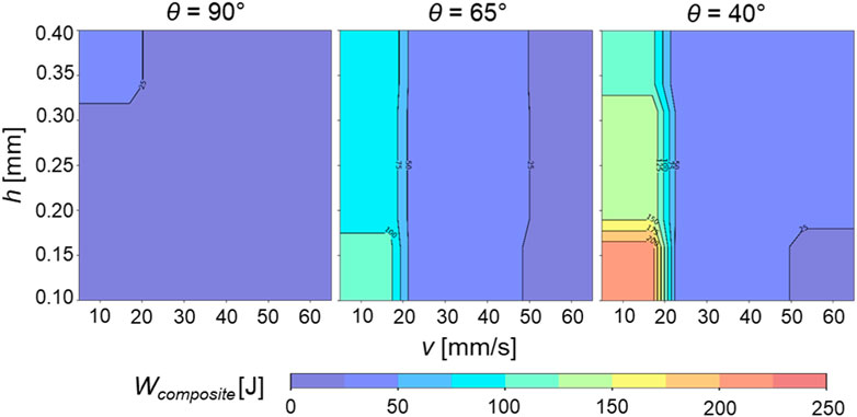
FIGURE 9. Contour plots for layer height h and printing speed v at different inclination angle θ levels, adopting Wcomposite as a response.
The high relative importance of v was most likely a product of the temperature evolution at the metal-polymer interface, which was a function of v itself (see Figure 10). As reported by (Belei et al., 2022a), the speed at which the coating layer is printed affects the temperature of the substrate both ahead and after the deposition. Slower prints cause a greater heat build-up effect (also reported by (Belei et al., 2022b), which in turn can (i) decrease the viscosity of the deposited polymer (Bechtel et al., 2020; Brostow et al., 2020; Calafel et al., 2020), allowing for a greater penetration into surface cavities and (ii) improve the wettability by providing enough energy to trigger a Cassie-Wenzel state transition (Ishino et al., 2004; Bormashenko, 2015; Su et al., 2016; Wang et al., 2016), which will be further discussed in Section 3.2.3. In either case, a stronger bond between metal and polymer would be achieved.
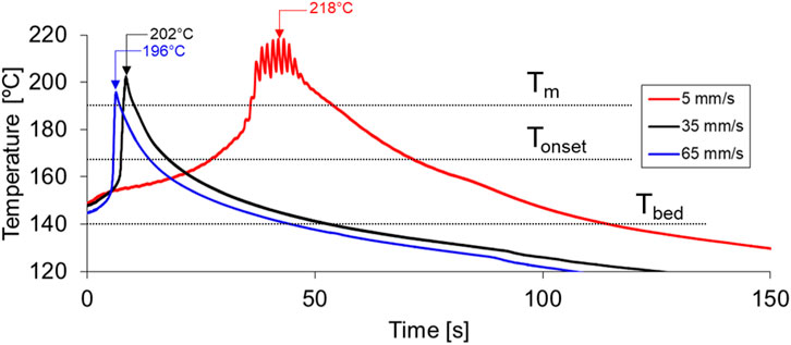
FIGURE 10. Temperature evolution during the coating layer deposition with different printing speeds. Layer height and inclination angles kept constant at 0.4 mm and 90°, respectively. Moment at which the nozzle passes over the thermocouple is indicated by an arrow. Tm, Tonset and Tbed denote Melting peak, melting onset and bed temperature, respectively.
Based on Figure 10, it can be observed that at v = 5 mm/s, the temperature of the measured region was already above Tonset for around 15 s before the deposition, staying above that level for an extra 30 s interval afterwards. This comes in stark contrast with faster prints, where the temperature is raised above Tonset almost instantaneously before the deposition and then falling off much sooner. Although this was also observed by (Belei et al., 2022a), the present findings showed temperature peaks up to 30°C higher in comparison, most likely as a result of the difference in the width of the coating layer (14 mm and 5 mm, respectively). This is in accordance with (Belei et al., 2022b), which discussed that the shorter are the successive nozzle paths, the more prominent the heat build-up effect will be. Ultimately, these conclusions suggest that, for the AddJoining approach on larger models, it is advisable to subdivide the coating layer in several narrow strips as a means to locally increase temperature and consequently adhesion. This strategy may substitute a further increase in Tbed, which is less energy efficient and also potentially harmful to the substrate (Moreira, 2020; Belei et al., 2022a).
3.2.3 Microstructural features and fractography analysis
During the AddJoining process, polymer from the coating layer was able to infiltrate irregularities present on the as-printed LPBF surfaces. This occurred regardless of roughness (i.e., θ), meaning that even cavities present on the roughest DS surfaces could potentially be infiltrated by the unreinforced polymer. However, Figure 11 shows that not every cavity could be fully infiltrated, since some of those contained air pockets that were subsequently entrapped by the coating layer. This phenomenon has been also observed with sandblasted surfaces with much lower surface roughness (Belei et al., 2022a). This was most likely a result of the polymer freezing while the metal-polymer interface was still at a transitional state between Cassie–Baxter (wetting prevented by entrapped air, metastable) and Wenzel (full wetting, stable) regimes, as mentioned earlier. Nevertheless, despite the occasional presence of air pockets at the interface, the joint strength could be considered satisfactory depending on the parameter combination, as discussed in Section 3.2.2.
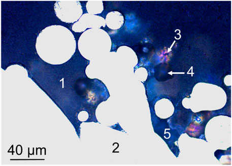
FIGURE 11. OM image showing the metal-polymer interface of a specimen produced with v = 5 mm/s, h = 0.25 mm and θ = 40°. (1) Coating layer; (2) substrate; (3) particle below the cross-sectional plane visible through the translucent polymer; (4) particle detached during metallography; (5) air pocket.
Under peeling, the intricate contact between substrate and coating layer led to a number of different fracture micromechanisms at the joint interface. Those affected both polymer and metal. For one, particles embedded in the coating layer deformed plastically and eventually failed, detaching themselves from the metallic substrate while remaining embedded in the polymer. An evidence for this can be seen in Figure 12, where a region previously occupied by a particle (or a group thereof) presented dimples; these features are a result of micro void coalescence, being normally observed on LPBF Ti-6Al-4V parts that experienced ductile fracture under tensile stress (Hooreweder and Sas, 2012; Cao et al., 2017; Gorsse et al., 2017). The extent of the individual dimpled regions depended on the prior contact area with the metallic substrate, with a diameter ranging from a few to tens of micrometers (Figures 12A, B, respectively). A similar observation was made by Englert et al. (2022), although in a milimetric scale; in their study, surface structures (i.e., pins) designed to enhance metal-polymer anchoring partially fractured as a result of shear stresses.
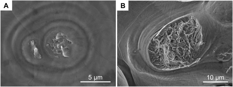
FIGURE 12. SE-SEM images from DS of L-PBF substrates after three-point bending test. Fracture surfaces resulting from the removal of (A) loosely-attached particle (θ = 90°) and (B) particle with a larger contact area (θ = 40°). Global crack propagation direction from top to bottom. Other process parameters: v = 5 mm/s, h = 0.40 mm.
Based on those observations, it can be reasonably assumed that the presence of partially-molten particles on as-printed L-PBF substrates contributed positively to the metal-polymer joint strength, as the breakage of those particles provided the joint with an additional energy dissipation mechanism (Kim et al., 2010; Libanori et al., 2016). Evidence of particles ripped off from the metallic substrate was found regardless of θ (see Figures 13A, B), being therefore a general tendency of the AddJoining process on as-printed LPBF substrates. The difference between θ values, however, was the amount of particles on the detached polymer after testing. Figures 13C, D show a comparison between detached coating layers from 90° to 40° substrates, respectively, whereby a much greater amount of detached particles could be observed on 40°. Such a difference can be attributed to the increasing presence of partially-molten particles on the DS as the inclination angle θ decreases, as discussed in Section 3.1. It also explains the increase in Wcomposite as θ decreases, as detected by the aforementioned prediction model (see Figure 9).

FIGURE 13. (A) and (B) SE-SEM images of metallic substrates after testing, with θ = 90° and 40°, respectively; white arrows indicate fractured areas previously occupied by particles. (C) and (D) BSE-SEM images of coating layers detached from substrates with θ = 90° and 40°, respectively; metallic particles are represented by brighter areas, while dark areas represent the surrounding polymer. For each picture, the global crack propagation occurred from top to bottom. Other process parameters: v = 5 mm/s and h = 0.40 mm.
A closer look at the embedded particles reveals not only the opposite fracture surfaces in relation to the ones presented in Figure 12, but also the situation of those particles with respect to the surrounding polymer as of the moment of their fracture. While fully enveloped particles expectedly broke off from the substrate (Figure 14A), particles that were only partially surrounded by polymer also presented signs of breakage (Figure 14B). This suggests that in spite of the occasional presence of air entrapment preventing a full embedding, those particles still contributed somehow to the overall joint strength. However, the fractured areas in those cases were found to be relatively small in comparison to the fully enveloped particles. This means that the presence of a neighboring air pocket most likely avoided particle breakage in situations where there was a larger contact area between partially-molten particle and substrate, hindering the effectiveness of the micromechanical interlocking.
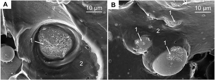
FIGURE 14. SE-SEM images of Ti-6Al-4V particles embedded in the coating layer after its detachment from the L-PBF substrate upon mechanical testing. (A) Particle totally surrounded by polymer; (B) partially surrounded particles. 1 indicates the respective facture surfaces for each individual particle; 2 represents the surrounding polymer. Process parameters: θ = 40°, v = 5 mm/s, h = 0.10 mm.
In most cases, however, the fracture of metallic particles did not occur; instead, the coating layer itself failed (see Figure 15), resulting in cavities and occasionally lacerations from ductile drawing (Greenhalgh, 2009). Cavities in the detached coating layer were a direct consequence of particles being pulled out from it (comparable to what is normally observed on fiber pullout in fiber-reinforced composites (Belei et al., 2022b). Similar cavities have been also reported in a previous study reproducing similar circumstances (Schmidt and Chen, 2022). Around such cavities, a damage zone comprised of plastically-deformed polymer was present (Figure 15-2), which has been identified elsewhere as well (Seo et al., 2021). The presence of those features is another indication that the interface failed under peeling loading. In this scenario, the presence of lacerations (see Figure 15-3) would also be expected, as previously observed for the AddJoining approach using sandblasted Ti-6Al-4V substrates (Belei et al., 2022a).
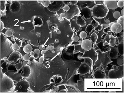
FIGURE 15. SE - SEM images of the as-tested coating layer surface. Partially-molten Ti-6Al-4V particles are indicated by 1; cavities resulting from the particle pullout are indicated by 2; lacerations as a result of ductile drawing are indicated by 3. Process parameters: θ = 40°, v = 5 mm/s, h = 0.40 mm.
While lacerations resulting from ductile drawing were somewhat discernable on the detached coating layer (as seen in Figure 15-3), they could be better observed as a part of polymer leftovers found on the metallic substrate after testing, see Figure 16. However, polymer residue on the substrate was not present on all conditions, being instead limited to specimens with low h values. In those cases, polymer residue was found surrounded by partially-molten particles, which previously constituted deep, intricate cavities where molten polymer could penetrate during AddJoining. The exact same tendency was also observed on rolled, sandblasted substrates (Belei et al., 2022a), where low h values also led to polymer residue on the metallic substrate. In the referred study, it was suggested that the coating layer—acting as a ductile interphase between metal and composite—was able to store energy via plastic deformation as the test progressed. Thus, decreasing h reduced the amount of ductile interphase material and consequently the amount of storable energy as well. Eventually, this resulted in two different outcomes: (i) at low enough h values (h = 0.10 mm), the coating layer torn apart before the onset of metal-polymer delamination; or (ii) for higher h values (h = 0.25 mm and above), detaching the polymer from the metal required less energy than tearing the coating layer, which led to the former occurring before the latter.
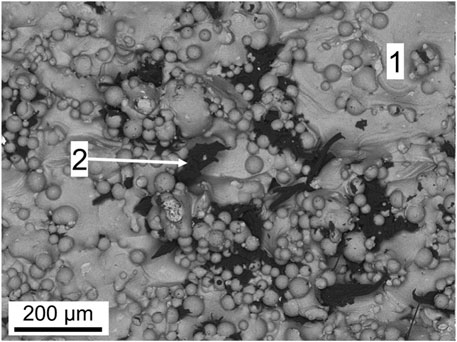
FIGURE 16. BSE-SEM images of metal substrate (1) after three-point bending test. Polymer leftovers trapped by partially molten particles is indicated by 2. Process parameters: θ = 40°, v = 5 mm/s, h = 0.10 mm.
A fundamental difference between the present study and (Belei et al., 2022a) is, however, the surface roughness of the respective substrates. The sandblasted pre-treatment on rolled substrates (the strategy utilized in the referred study) resulted in a considerably lower areal surface roughness (Sa = 1.4 µm), therefore providing the deposited polymer with less anchoring sites. The referred study suggested that the outcome (ii) (i.e., coating layer detachment without failure) could cease to occur by increasing the metal-polymer interfacial strength, which in turn could be done, for example, by increasing the substrate roughness. However, according to the present findings, substrate roughness did not seem to matter: under peeling stresses, thinner coating layers were more prone to failure than thicker ones, regardless of the substrate roughness.
In terms of the “global” hybrid joint strength, however, a conclusion on this subject is not as straightforward. On the one hand, the previous study with sandblasted substrates (Belei et al., 2022a) suggested that h was indeed a statistically-significant parameter, with a positive effect on the response (in that case Fc). On the other hand, the present findings show that the influence of h had a negative effect on the response (Wcomposite), although only observable at low v and θ values. However, the apparent contradiction may stem from a multitude of factors, being a direct comparison difficult due the different experimental approaches. For one, the referred study only evaluated the effect of h using a constant printing speed of v = 35 mm/s and at a surface roughness level that could not be achieved by any θ value. There may exist an interaction of higher order between h, v and θ, perhaps only identifiable beyond the hereby evaluated ranges, which could potentially explain the observed contradiction.
4 Conclusion
Based on the results collected during the present work, the following conclusions can be drawn.
- Fully additively-manufactured metal-polymer hybrid specimens, consisted of a LPBF Ti-6Al-4V/PA-CF material combination, were successfully produced using the FFF-based “AddJoining” approach. The LPBF specimens were 3D-printed with several inclination angles, resulting in different levels of surface roughness. The polymer was printed using a two-step approach, whereby a “coating layer” of unreinforced PA was firstly deposited, with subsequent reinforced PA layers 3D-printed on it.
- A standardized three-point bending test, originally designed to test the strength adhesives on solid substrates, was successfully adapted for the 3D-printed hybrid specimens. The main output of this test was the force at which the polymer detaches from the metallic substrate (Fc), which later can be converted into the energy absorbed at the interface up to the detachment (hereby termed Wcomposite, measured in J). Average Wcomposite results showed a strong dependence of the process parameters, ranging between 4.9 J (weak joint) and 214.5 J (strong joint).
- A ML approach based on a Decision Tree Regression algorithm was applied to determine the influence of process parameters (i.e., coating layer height and printing speed, as well as the inclination angle with which the LPBF substrates were printed) on the responses from the three-point bending test. The model achieved a coefficient of determination (R2) of 0.997 and 0.860 for the training and test sets, respectively, which were considered satisfactory. Thereby it was possible to conclude that printing speed and inclination angle (i.e., substrate roughness) were, in order, the most relevant parameters dictating the hybrid joint strength, with the coating layer height exhibiting only a minor influence.
- Slower coating layer printing speeds were related to an increased temperature at the metal-polymer interface, which theoretically decreases the polymer viscosity while increasing wettability. On the same note, rougher substrates offered more cavities into which the molten polymer could penetrate. Those acted as anchoring sites, thereby increasing the joint strength.
- After three-point bending tests, partially-molten particles resulting from the LPBF process either suffered ductile fracture or were pulled out of the coating layer. Either mechanism is thought to have contributed to the energy dissipation capabilities of the metal-polymer interface. Additionally, the coating layer itself exhibited signs of ductile deformation, as evidenced by numerous lacerations found on the fracture surfaces. Leftovers of polymer on the metal surface were not prevalent, being limited mostly to conditions with low coating layer height.
Data availability statement
The original contributions presented in the study are included in the article/Supplementary Material, further inquiries can be directed to the corresponding authors.
Author contributions
CB performed experimental work, data analysis and wrote this manuscript. PE provided the prediction modelling and data analysis, as well as reviewed the manuscript. BM provided the LPBF substrates and powder data, discussed the LPBF-related contents and reviewed the manuscript. STA-F provided the funding, infrastructure, supervised the experimental work and reviewed the manuscript.
Funding
The work was supported by the Austrian Research Promotion Agency (FFG) [“TAKEOFF” PILOT, grant number 852796, 2018] and the BMK—The Austrian Ministry for Climate Action, Environment, Energy, Mobility, Innovation and Technology.
Acknowledgments
The authors would like to acknowledge the Open Access Funding by the Graz University of Technology.
Conflict of interest
The authors declare that the research was conducted in the absence of any commercial or financial relationships that could be construed as a potential conflict of interest.
Publisher’s note
All claims expressed in this article are solely those of the authors and do not necessarily represent those of their affiliated organizations, or those of the publisher, the editors and the reviewers. Any product that may be evaluated in this article, or claim that may be made by its manufacturer, is not guaranteed or endorsed by the publisher.
Supplementary material
The Supplementary Material for this article can be found online at: https://www.frontiersin.org/articles/10.3389/fmats.2023.1202281/full#supplementary-material
References
Alhmoudi, A., Sheikh-Ahmad, J., Almaskari, F., and Bojanampati, S. 2022. “Joining of polymer-metal hybrid structures by fused deposition modelling.” In 2022 Advances in Science and Engineering Technology International Conferences (ASET), 1–5. doi:10.1109/ASET53988.2022.9734841
Amancio-Filho, S., and Blaga, L. A. (2018). Joining of polymer-metal hybrid structures: Principles and applications. doi:10.1002/9781119429807
Ang, H. Q., Abbott, T. B., Zhu, S., Gu, C., and Easton, M. A. (2016). Proof stress measurement of die-cast magnesium alloys. Mater. Des. 112, 402–409. doi:10.1016/j.matdes.2016.09.088
Bechtel, S., Meisberger, M., Klein, S., Tobias, H., Quirin, S., and Herrmann, H.-G. (2020). Estimation of the adhesion interface performance in aluminum-PLA joints by thermographic monitoring of the material extrusion process. Materials 13 (15), 3371. doi:10.3390/ma13153371
Bechtel, S., Schweitzer, R., Frey, M., Busch, R., and Herrmann, H.-G. (2022). Material extrusion of structural polymer–aluminum joints—examining shear strength, wetting, polymer melt rheology and aging. Materials 15 (9), 3120. doi:10.3390/ma15093120
Belei, C., Jana, J., and Sergio, T. A.-F. (2022b). Fused-filament fabrication of short carbon fiber-reinforced polyamide: Parameter optimization for improved performance under uniaxial tensile loading. Polymers 14 (7), 1292. doi:10.3390/polym14071292
Belei, C., Pommer, R., and Amancio-Filho, S. T. (2022a). Optimization of additive manufacturing for the production of short carbon fiber-reinforced polyamide/Ti-6Al-4V hybrid parts. Mater. Des. 219, 110776. doi:10.1016/j.matdes.2022.110776
Benito, J. A., Cobo, R., Lei, W., Calvo, J., and Cabrera, J. M. (2016). Stress–strain response and microstructural evolution of a FeMnCAl TWIP steel during tension–compression tests. Mater. Sci. Eng. A 655, 310–320. doi:10.1016/j.msea.2016.01.004
Birro, T. V., Aufray, M., Paroissien, E., and Lachaud, F. (2021). Assessment of interface failure behaviour for brittle adhesive using the three-point bending test. Int. J. Adhesion Adhesives 110, 102891. doi:10.1016/j.ijadhadh.2021.102891
Bormashenko, E. (2015). Progress in understanding wetting transitions on rough surfaces. Adv. Colloid Interface Sci. Reinhard Mill. Honorary Issue 222, 92–103. doi:10.1016/j.cis.2014.02.009
Breiman, L., Friedman, J., Stone, C. J., and Olshen, R. A. (1984). Classification and regression trees. Taylor and Francis.
Brostow, W., Gonçalez, V., Perez, J. M., and Shipley, S. C. (2020). Wetting angles of molten polymers on thermoelectric solid metal surfaces. J. Adhesion Sci. Technol. 34 (11), 1–9. doi:10.1080/01694243.2019.1701893
Calafel, I., Aguirresarobe, R. H., Peñas, M. I., Santamaria, A., Tierno, M., Conde, J. I., et al. (2020). Searching for rheological conditions for FFF 3D printing with PVC based flexible compounds. Materials 13 (1), 178. doi:10.3390/ma13010178
Cao, S., Chen, Z., Lim, C. V. S., Yang, K., Jia, Q., Jarvis, T., et al. (2017). Defect, microstructure, and mechanical property of Ti-6Al-4V alloy fabricated by high-power selective laser melting. JOM 69 (12), 2684–2692. doi:10.1007/s11837-017-2581-6
Carvalho, W. S., and Amancio-Filho, S. T. (2022). On the feasibility of joining additively-manufactured 316L stainless steel and poly-ether-ether-ketone by ultrasonic energy. Addit. Manuf. Lett. 3, 100098. doi:10.1016/j.addlet.2022.100098
Charles, A., Ahmed, E., Paggi, U., Thijs, L., Hagenmeyer, V., and Scholz, S. (2021). Down-facing surfaces in laser powder bed fusion of Ti6Al4V: Effect of dross formation on dimensional accuracy and surface texture. Addit. Manuf. 46, 102148. doi:10.1016/j.addma.2021.102148
Chueh, Y.-H., Wei, C., Zhang, X., and Lin, L. (2020). Integrated laser-based powder bed fusion and fused filament fabrication for three-dimensional printing of hybrid metal/polymer objects. Addit. Manuf. 31, 100928. doi:10.1016/j.addma.2019.100928
Covarrubias, E. E., and Eshraghi., M. (2018). Effect of build angle on surface properties of nickel superalloys processed by selective laser melting. JOM 70 (3), 336–342. doi:10.1007/s11837-017-2706-y
Englert, L., Heuer, A., Engelskirchen, M. K., Frölich, F., Dietrich, S., Liebig, W. V., et al. (2022). Hybrid material additive manufacturing: Interlocking interfaces for fused filament fabrication on laser powder bed fusion substrates. Virtual Phys. Prototyp. 17 (3), 508–527. doi:10.1080/17452759.2022.2048228
Falck, R., Goushegir, S. M., dos Santos, J. F., and Amancio-Filho, S. T. (2018). AddJoining: A novel additive manufacturing approach for layered metal-polymer hybrid structures. Mater. Lett. 217, 211–214. doi:10.1016/j.matlet.2018.01.021
Falck, R., Jorge, F., and Sergio, T. A.-F. (2019). Microstructure and mechanical performance of additively manufactured aluminum 2024-T3/acrylonitrile butadiene styrene hybrid joints using an AddJoining technique. Materials 12 (6), 864. doi:10.3390/ma12060864
Feng, S., Kamat, A. M., Sabooni, S., and Pei, Y. (2021). Experimental and numerical investigation of the origin of surface roughness in laser powder bed fused overhang regions. Virtual Phys. Prototyp. 16, S66–S84. doi:10.1080/17452759.2021.1896970
Filho, S., and Falck, R. (2018). Method for producing a layered component. Germany DE102016121267A1. filed November 7, 2016, and issued May 9, 2018. Available at: https://patents.google.com/patent/DE102016121267A1/en.
Friedman, J. H. (2001). Greedy function approximation: A gradient boosting machine. Ann. Statistics 29 (5), 1189–1232. doi:10.1214/aos/1013203451
Genty, S., Sauvage, J.-B., Philippe, T., and Aufray, M. (2017). Experimental and statistical study of three adherence tests for an epoxy-amine/aluminum alloy system: Pull-off, single lap joint and three-point bending tests. Int. J. Adhesion Adhesives 79, 50–58. doi:10.1016/j.ijadhadh.2017.09.004
Gorsse, S., Hutchinson, C., Goune, M., and Banerjee, R. (2017). Additive manufacturing of metals: A brief review of the characteristic microstructures and properties of steels, Ti-6Al-4V and high-entropy alloys. Sci. Technol. Adv. Mater. 18, 584–610. doi:10.1080/14686996.2017.1361305
Hasemann, G., Müller, C., Grüner, D., Wessel, E., and Krüger, M. (2019). Room temperature plastic deformability in V-rich V–Si–B alloys. Acta Mater. 175, 140–147. doi:10.1016/j.actamat.2019.06.007
Hastie, T., Tibshirani, R., and Friedman, J. (2009). Springer series in statistics. New York, NY: Springer. doi:10.1007/978-0-387-84858-7The elements of statistical learning
Hertle, S., Tobias, K., Wörz, A., and Drummer, D. (2020). Production of polymer-metal hybrids using extrusion-based additive manufacturing and electrochemically treated aluminum. Addit. Manuf. 33, 101135. doi:10.1016/j.addma.2020.101135
Hofele, M., Roth, A., Schanz, J., Harrison, D. K., De Silva, A. K. M., and Riegel, H. (2021). Laser polishing of laser powder bed fusion AlSi10Mg parts—influence of initial surface roughness on achievable surface quality. Mater. Sci. Appl. 12, 15–41. doi:10.4236/msa.2021.121002
Hooreweder, B. V., Moens, D., Boonen, R., Kruth, J., and Sas, P. 2012. Analysis of fracture toughness and crack propagation of Ti6Al4V produced by selective laser melting. Adv. Eng. Mater. 14 (1–2), 92–97. doi:10.1002/adem.201100233
Ishino, C., Ko, O., and Quéré, D. (2004). Wetting transitions on rough surfaces. Europhys. Lett. 68, 419–425. doi:10.1209/epl/i2004-10206-6
Kim, W.-S., Yun, I. H., Jung, H. T., Il-Han, Y., Jung-Ju, L., and Hee-Tae, J. 2010. “Evaluation of mechanical interlock effect on adhesion strength of polymer–metal interfaces using micro-patterned surface topography.” Int. J. Adhesion Adhesives 30 (6): 408–417. doi:10.1016/j.ijadhadh.2010.05.004
Koutiri, I., Pessard, E., Peyre, P., Amlou, O., and De Terris, T. (2018). Influence of SLM process parameters on the surface finish, porosity rate and fatigue behavior of as-built inconel 625 parts. J. Mater. Process. Technol. 255, 536–546. doi:10.1016/j.jmatprotec.2017.12.043
Lambiase, F., Silvia Ilaria, S., Lee, C.-J., Ko, D.-C., and Liu, F. (2021). A state-of-the-art review on advanced joining processes for metal-composite and metal-polymer hybrid structures. Materials 14 (8), 1890. doi:10.3390/ma14081890
Leeden, M., and Frens, G. (2002). Surface properties of plastic materials in relation to their adhering performance. Adv. Eng. Mater. 4, 280–289. doi:10.1002/1527-2648(20020503)4:5<280:AID-ADEM280>3.0.CO;2-Z
Libanori, R., Carnelli, D., Rothfuchs, N., Binelli, M. R., Zanini, M., Nicoleau, L., et al. (2016). Composites reinforced via mechanical interlocking of surface-roughened microplatelets within ductile and brittle matrices. Bioinspiration Biomimetics 11 (3), 036004. doi:10.1088/1748-3190/11/3/036004
Liu, J. H., Shi, Y. S., Lu, Z. L., Xu, Y., Chen, K. H., and Huang, S. H. (2007). Manufacturing metal parts via indirect SLS of composite elemental powders. Mater. Sci. Eng. A 444 (1), 146–152. doi:10.1016/j.msea.2006.08.070
Liu, Z. Y., Li, C., Fang, X. Y., and Guo, Y. B. (2018). Energy consumption in additive manufacturing of metal parts. Procedia Manuf. 46th SME North Am. Manuf. Res. Conf. NAMRC 26, 834–845. doi:10.1016/j.promfg.2018.07.104
Lizzul, L., Sorgato, M., Bertolini, R., Ghiotti, A., and Bruschi, S. (2021)., 102. Surface finish of additively manufactured Ti6Al4V workpieces after ball end millingProcedia CIRP, 18th CIRP Conf. Model. Mach. Operations (CMMO) Ljubljana, Slovenia, 228–233. doi:10.1016/j.procir.2021.09.039
Mehrpouya, M., Tuma, D., Vaneker, T., Afrasiabi, M., Bambach, M., and Gibson, I. (2022). Multimaterial powder bed fusion techniques. Rapid Prototyp. J. 28 (11), 1–19. doi:10.1108/RPJ-01-2022-0014
Meier, B., Godja, N., Warchomicka, F., Belei, C., Schäfer, S., Schindel, A., et al. (2022a). Influences of surface, heat treatment, and print orientation on the anisotropy of the mechanical properties and the impact strength of Ti 6Al 4V processed by laser powder bed fusion. J. Manuf. Mater. Process. 6 (4), 87. doi:10.3390/jmmp6040087
Meier, B., Warchomicka, F., Petrusa, J., Paul, A., Wosik, J., Kaindl, R., et al. (2022b). Influence of powder production process and properties on material properties of Ti6Al4V manufactured by L-PBF. Int. J. Adv. Manuf. Technol. 123, 1577–1588. doi:10.1007/s00170-022-10250-y
Melia, M. A., Jesse, G. D., Koepke, J. R., Saiz, D. J., Jared, B. H., and Schindelholz, E. J. (2020). How build angle and post-processing impact roughness and corrosion of additively manufactured 316L stainless steel. Npj Mater. Degrad. 4 (1), 1–11. doi:10.1038/s41529-020-00126-5
Moreira, M. F. R. (2020). A new additive manufacturing technique for layered metal-composite hybrid structures. Thesis, Tech. Univ. Hambg. doi:10.15480/882.2961.4
Ngo, T. D., Kashani, A., Imbalzano, G., Nguyen, K. T. Q., and Hui, D. (2018). Additive manufacturing (3D printing): A review of materials, methods, applications and challenges. Compos. Part B Eng. 143, 172–196. doi:10.1016/j.compositesb.2018.02.012
Ni, C., Shi, Y., and Jia, L. (2018). Effects of inclination angle on surface roughness and corrosion properties of selective laser melted 316L stainless steel. Mater. Res. Express 6 (3), 036505. doi:10.1088/2053-1591/aaf2d3
Oliveira, G. H. M., Belei, C., de Carvalho, W. S., Canto, L. B., and Amancio-Filho, S. T. (2023). On the fully additive manufacturing of PC/AlSi10Mg hybrid structures. Mater. Lett. 330, 133378. doi:10.1016/j.matlet.2022.133378
Papazoglou, E. L., Karkalos, N. E., Karmiris-Obratański, P., and Markopoulos, A. P. (2022). On the modeling and simulation of slm and SLS for metal and polymer powders: A review. Archives Comput. Methods Eng. 29 (2), 941–973. doi:10.1007/s11831-021-09601-x
Pérez-Ruiz, J. D., Marin, F., Martínez, S., Lamikiz, A., Urbikain, G., and Norberto López de Lacalle, L. (2022). Stiffening near-net-shape functional parts of inconel 718 LPBF considering material anisotropy and subsequent machining issues. Mech. Syst. Signal Process. 168, 108675. doi:10.1016/j.ymssp.2021.108675
Raschka, S., and Mirjalili, V. (2019). Python machine learning: Machine learning and deep learning with Python, scikit-learn, and TensorFlow 2. Birmingham, United Kingdom: Packt Publishing Ltd.
Roche, A. A., Behme, A. K., and Solomon, J. S. (1982). A three-point flexure test configuration for improved sensitivity to metal/adhesive interfacial phenomena. Int. J. Adhesion Adhesives 2 (4), 249–254. doi:10.1016/0143-7496(82)90032-X
Sauvage, J.-B., Aufray, M., Jeandrau, J.-P., Chalandon, P., Poquillon, D., and Nardin, M. (2017). Using the 3-point bending method to study failure initiation in epoxide-aluminum joints. Int. J. Adhesion Adhesives 75, 181–189. doi:10.1016/j.ijadhadh.2017.03.011
Schmidt, K. T. A., and Chen, Z. W. (2022). Effect of surface morphology of Ti6Al4V alloy parts manufactured by electron beam powder bed fusion on bonding strength of adhesive joints. Addit. Manuf. Lett. 3, 100059. doi:10.1016/j.addlet.2022.100059
Seo, J. S., Ho, T. J., and Han, T. H. (2021). Peeling mechanism of interlocked interface between etched acrylonitrile-butadiene-styrene and electroplated metal layer. Surfaces Interfaces 26, 101337. doi:10.1016/j.surfin.2021.101337
Simson, D., and Subbu, S. K. (2022). Effect of process parameters on surface integrity of LPBF Ti6Al4V.” Procedia CIRP. 6th CIRP Conf. Surf. Integr. 108, 716–721. doi:10.1016/j.procir.2022.03.111
Skalon, M., Meier, B., Gruberbauer, A., de Traglia Amancio-Filho, S., and Sommitsch, C. (2020). Stability of a melt pool during 3D-printing of an unsupported steel component and its influence on roughness. Materials 13 (3), 808. doi:10.3390/ma13030808
Su, J., Charmchi, M., and Sun, H. (2016). A study of drop-microstructured surface interactions during dropwise condensation with quartz crystal microbalance. Sci. Rep. 6, 35132. doi:10.1038/srep35132
Ultimaker Nylon TDS." 2023. Accessed April 27, 2023. Available at: https://support.makerbot.com/s/article/1667410781976.
Ultrafuse® PAHT CF15." 2023. Accessed April 27, 2023. Available at: https://forward-am.com/material-portfolio/ultrafuse-filaments-for-fused-filaments-fabrication-fff/reinforced-filaments/ultrafuse-paht-cf15/.
Wang, Z., Elimelech, M., and Lin, S. (2016). Environmental applications of interfacial materials with special wettability. Environ. Sci. Technol. 50, 2132–2150. doi:10.1021/acs.est.5b04351
Yadollahi, A., Shamsaei, N., Thompson, S. M., Elwany, A., and Bian, L. (2017). Effects of building orientation and heat treatment on fatigue behavior of selective laser melted 17-4 PH stainless steel. Int. J. Fatigue, Fatigue Fract. Behav. Addit. Manuf. Parts 94, 218–235. doi:10.1016/j.ijfatigue.2016.03.014
Keywords: additive manufacturing, fused-filament fabrication, laser powder bed fusion, metal-polymer hybrid joining, three-point bending
Citation: Belei C, Effertz PS, Meier B and Amancio-Filho ST (2023) Additive manufacturing of metal-polymer hybrid parts: the influence of as-printed LPBF surface roughness on the joint strength. Front. Mater. 10:1202281. doi: 10.3389/fmats.2023.1202281
Received: 07 April 2023; Accepted: 12 May 2023;
Published: 26 May 2023.
Edited by:
Jingjun Wu, Zhejiang University, ChinaReviewed by:
Luhao Yuan, Nanjing University of Aeronautics and Astronautics, ChinaRafael Comesaña, University of Vigo, Spain
Yuewei Li, Huaqiao University, China
Lin Fenglong, Xiamen Institute of Rare Earth Materials, China
Copyright © 2023 Belei, Effertz, Meier and Amancio-Filho. This is an open-access article distributed under the terms of the Creative Commons Attribution License (CC BY). The use, distribution or reproduction in other forums is permitted, provided the original author(s) and the copyright owner(s) are credited and that the original publication in this journal is cited, in accordance with accepted academic practice. No use, distribution or reproduction is permitted which does not comply with these terms.
*Correspondence: C. Belei, Y2FybG9zLmJlbGVpZmVsaWNpYW5vQHN0dWRlbnQudHVncmF6LmF0; S. T. Amancio-Filho, c2VyZ2lvLmFtYW5jaW9AdHVncmF6LmF0