 Zhen Wang
 Changbao Qi3
- 1Urban Rail Research Institute, Shandong Polytechnic, Jinan, China
- 2Guo Rui Skills Master Studio, Shandong Polytechnic, Jinan, China
- 3College of Locomotive and Rolling Stock Engineering, Dalian Jiaotong University, Dalian, China
The overlap rate has a significant impact on the quality and performance of laser cladding coatings. In order to prepare high wear-resistant laser cladding coatings. Single and multi-pass Fe-Ni-Ti composite coatings were prepared on the surface of 45 steel using a semiconductor laser. The microstructure and phase composition of the fusion layers were analyzed using metallographic microscopy, XRD diffraction, scanning electron microscopy, and energy dispersive spectrometry. Friction coefficients and microhardness of fusion layers with different overlap ratios were tested using a multifunctional surface performance tester and a microhardness tester. The wear performance of coatings with different overlap ratios was tested using a wear testing machine.The results indicate that when 6% Ti was simultaneously added to the Invar alloy matrix during the laser fusion of Fe-Ni-Ti alloy coatings, the phase composition of the fusion layer mainly consists of γ-[Fe, Ni] austenite, Fe3Ni2, α-Fe, and other metallic compounds. Simultaneously, in-situ formation of TiC reinforcement is dispersed in the matrix of γ-[Fe, Ni] solid solution. When the overlap ratio is 46%, the fusion layer exhibits a uniform, dense structure with fewer defects and higher coating hardness, resulting in improved wear resistance. At this point, the microhardness of the fusion layer is 450 HV, 1.5 times that of the substrate material and 2.2 times that of the base material. The friction coefficient on the coating surface is 0.412, with a percentage weight loss of 0.17%. The wear theory of the cladding layer is mainly adhesive wear, which also includes abrasive wear.
1 Introduction
Laser cladding technology possesses the characteristics of rapid heating and rapid cooling, leading to increased undercooling during metal crystallization, refinement of grain structure in the cladding layer, and improved overall performance, resulting in its widespread application. However, cladding materials exhibit diversity and often have significantly different coefficients of thermal expansion from the substrate. This generates stress during the cladding process, and when the stress reaches its limit, it can lead to the formation of cracks in the cladding layer, ultimately reducing its service life (Zhou et al., 2008; Zhao et al., 2012; Fu et al., 2016; Zhu et al., 2021). Invar alloy is a nickel-based high-iron alloy with a unique Fe-Ni ratio that results in the formation of a [Fe, Ni] austenite structure in which Ni dissolves in γ-Fe. This unique composition leads to a low coefficient of thermal expansion, significantly reducing the occurrence of cracks and defects in the cladding layer (Shiga, 1996; Vinogradov et al., 2003; Zhan et al., 2019). However, single Invar alloy cladding layers exhibit lower strength, hardness, and wear resistance, limiting the scope of their application in laser cladding. Previous research by the authors has shown that the addition of Ti elements to Invar alloy results in the in-situ formation of TiC reinforcement in the cladding layer, dispersed within the matrix of γ-[Fe, Ni] solid solution. This has a significant strengthening effect on the wear resistance of the cladding layer, allowing the production of coatings with high wear resistance and fewer defects (Xv et al., 2023).
Due to the limited area of a single coating fusion, multiple fusion passes are necessary for the production application of fused coatings. During the process of multiple fusions, there is an overlap between adjacent fused layers, and the ratio of this overlap width to the width of a single fusion pass is referred to as the overlap rate. The optimal overlap rate varies depending on the fusion material used. For instance, Jun Cao and colleagues investigated the impact of the overlap rate on the crystallization of Inconel 718 high-temperature alloy and observed that a higher overlap rate results in finer recrystallization (Cao et al., 2013). The author observed that variations in the overlap rate significantly impact both the quality and performance of Fe-Ni-Ti composite coatings. However, there is a scarcity of research on this aspect. Therefore, investigating the appropriate overlap ratio is of great importance in the preparation of highly wear-resistant Fe-Ni-Ti coatings.
Based on this, this study leverages the Invar effect of Invar alloy to perform laser cladding of Fe-Ni-Ti composite coatings on the surface of 45 steel, conducting both single-pass and multi-pass overlay fusion experiments. The research investigates the microstructure of Fe-Ni-Ti composite coatings and the impact of different overlap ratios on the structure and performance of Fe-Ni-Ti coatings. Consequently, it aims to determine the optimal overlap ratio and reveal the mechanism by which the overlap ratio affects the Fe-Ni-Ti overlay fusion coating.
2 Materials and methods for the experiment
The base material used in this experiment is quenched and tempered 45 steel, with a dimension of 50 mm × 50 mm × 15 mm. Prior to the experiment, the base material underwent abrasive brushing pretreatment to reduce reflectivity and maximize energy absorption. The specific composition of the base material is shown in Table 1; the fusion powder has a mass fraction of 57.8% Fe, 36% Ni, 6% Ti, and 0.2% C, with a powder particle size ranging from 74 to 104 µm (-140 to +200 mesh).
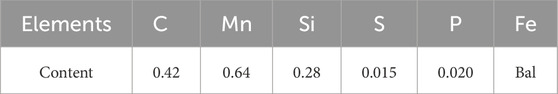
Table 1. The main ingredients of 45 steel (wt%).
Titanium (Ti) is a reactive element and is prone to react at high temperatures during ball milling. Therefore, the ball milling experiments were conducted under ethanol protection. The addition of ethanol during the ball milling process could absorb a significant amount of heat, lowering the ball milling temperature and stabilizing the Ti in the cladding material. The prepared powder was subjected to ethanol-protected ball milling in an XQM-2L vertical planetary ball mill using agate grinding balls with diameters of 6, 10, and 20 mm, where large balls accounted for 20% of the total weight, medium-sized balls for 50%, and small balls for 30%. The ball milling duration was 10 h, with a ball-to-material ratio of 3:1, and a ball milling speed of 250 r/min. The laser used in the experiment was an LDM2500-60 semiconductor laser, and a synchronous powder feeding method was employed for cladding. During the cladding experiments, coaxial argon (Ar) gas protection was applied with an Ar gas flow rate of 15 L/min. The laser cladding parameters were optimized in prior experiments and included a laser power of 1400 W, a beam diameter of 3.2 mm, a scanning speed of 270 mm/min, and a powder feeding rate of 25 g/min. Both single-pass cladding and multi-pass overlay experiments were conducted, with the multi-pass overlay experiments utilizing overlap ratios of 42%, 44%, 46%, 48%, and 50%.During multi-pass overlay, the numerical control system of the laser processing machine is utilized to control the repetition degree of the laser spot, thereby achieving control over different overlap rates.
The cladding samples were cut into 30 mm sections along the cladding direction using a wire cutting machine, and the cladding layer surfaces were cleaned. The macroscopic appearance of the cladding layer was observed under an optical microscope (OM), and the dimensions of various regions of the cladding layer were measured using ImageJ software. Additionally, samples were cut to prepare metallographic specimens of the Fe-Ni-Ti cladding layer, and metallographic images were captured. The microstructure of the Fe-Ni-Ti cladding layer was examined using a Tescan VEGAII lMH scanning electron microscope (SEM), and energy dispersive spectroscopy (EDS) analysis was performed using the built-in EDS of the SEM. X-ray diffraction (XRD) analysis was conducted to determine the phase composition of the cladding layer. The hardness of the cladding layer was measured using an HV-1000IS microhardness tester with a load of 200 g and a loading time of 10 s. Hardness testing was carried out by indenting the cladding layer in 20 different points in the cladding area, and the average value was calculated. The Fe-Ni-Ti cladding layer was cut into standard specimens using a wire cutting machine, and the friction coefficient of the cladding layer was tested using an MFT-4000 multifunctional material surface performance tester with a load of 50 N and a test duration of 20 min. The friction coefficient fluctuation curve was studied. Wear tests were conducted on the cladding layer, involving an initial grinding period of 5 min followed by ultrasonic cleaning and weighing. Subsequently, the wear test was performed for 20 min, followed by cleaning and weighing to determine the percentage weight loss due to wear. The worn surface of the cladding layer was observed using a scanning electron microscope. The specific experimental procedure is illustrated in Figure 1.
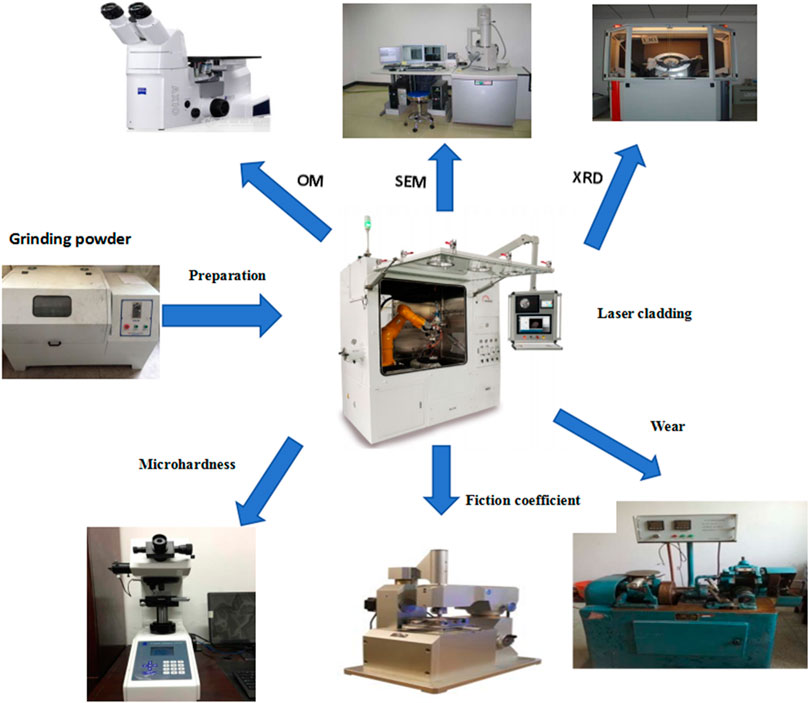
Figure 1. Experimental Procedure (The experimental procedure primarily involves first preparing the fusion powder, followed by the fabrication of Fe-Ni-Ti coatings with different overlap rates. Subsequently, the microstructure of the fused coatings is examined, and finally, various properties of Fe-Ni-Ti coatings with different overlap rates are tested.).
3 Experimental conclusion and discussion
3.1 Microstructural analysis of the Fe-Ni-Ti composite coating
Figures 2A,B depicts the macroscopic cross-sectional image of a single-pass fused Fe-Ni-Ti composite coating. In the figure, it is evident that the cladding layer exhibits three characteristic regions from the surface to the substrate, including the cladding zone (CL), the bond zone (BZ), and the heat-affected zone (HAZ) (Gong et al., 2023). There is a distinct boundary between the BZ and HAZ regions, which represents the metallurgical joining point between the substrate and the cladding layer. From the HAZ to the matrix, a gradual transition can be observed as energy is transmitted downward, leading to the dilution of some cladding material into the HAZ region. The HAZ region has been measured to be approximately 0.4–0.6 mm using ImageJ software. Figure 2C presents the microstructure of the central part (Area D) of the cladding layer at 4,000 times magnification under a scanning electron microscope. The fusion zone is primarily composed of equiaxed crystals with few fine dendrites, and most grain diameters range between 10 μm and 12 μm. This is primarily attributed to the significant undercooling during the cladding process, leading to a substantial increase in nucleation rate, resulting in fine grains. Furthermore, the figure reveals fewer defects such as cracks and pores in the single-pass cladding layer (Manoj et al., 2023).
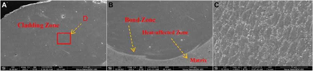
Figure 2. Fe-Ni-Ti single-pass laser cladding coating: (A) Upper part of the cladding layer; (B) Bottom of the cladding layer (C) Microstructure at 4,000x in the fusion zone (The laser cladding coating can be subdivided into distinct regions, with grain sizes ranging from 10 to 12 μm in laser cladding region D).
High-magnification scanning electron microscopy was employed to observe the microstructure of the cladding layer, as shown in Figure 3A. As shown in the figure, the microstructure of the cladding coating is very uniform, and in the grain boundaries (Region E), TiC particles obstruct grain dislocations, resulting in grain refinement. Combined with the X-ray diffraction (XRD) analysis in Figure 3B, it can be concluded that the phase in the cladding layer consists of [Fe, Ni] austenite with Ni dissolved in γ-Fe, existing in the form of a solid solution Fe0.64Ni0.36. This is a characteristic microstructure of Invar, indicating that the cladding layer maintains the Invar effect during the cladding process. Additionally, the microstructure contains small amounts of α-Fe, Fe3Ni2, and in-situ-generated TiC reinforcement phase (Wegener et al., 2021). Furthermore, Figure 3C reveals prominent precipitates in the grain boundaries. Complementing this observation, energy dispersive spectroscopy (EDS) surface scanning analysis of C and Ti elements in the Fe-Ni-Ti cladding layer microstructure indicates the distribution of TiC reinforcement phase within the γ-[Fe, Ni] solid solution, with a more concentrated presence at the grain boundaries, demonstrating enrichment (Penelle and Baudin, 2010).
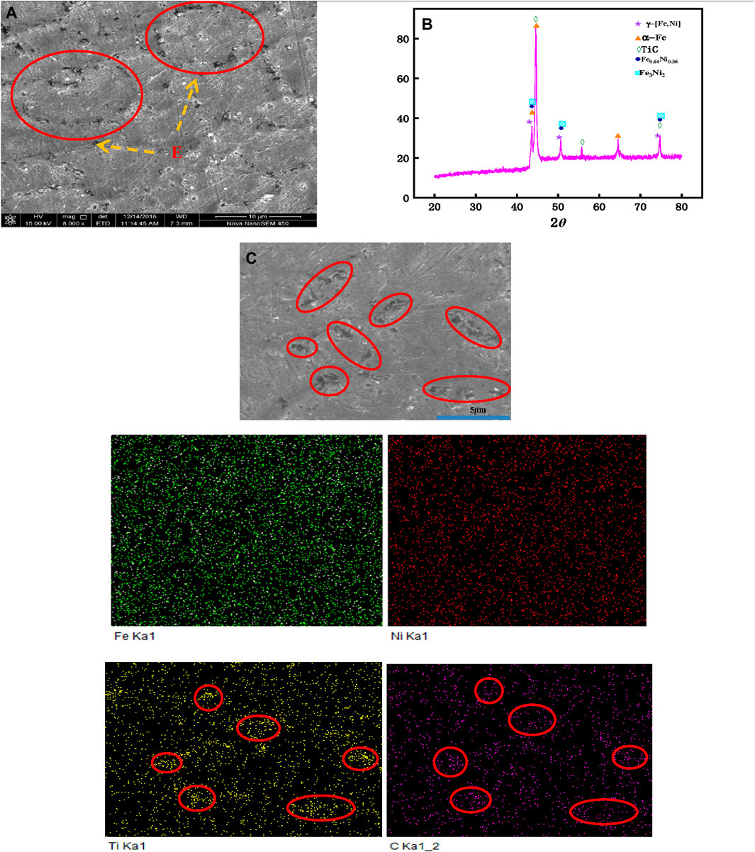
Figure 3. Microstructure of surface cladding layer: (A) Microstructure of Fe-Ni-Ti coating under 8000X magnification; (B) X-ray diffraction (XRD) analysis of the Fe-Ni-Ti coating; (C) Energy dispersive spectroscopy (EDS) surface scanning of the Fe-Ni-Ti coating. (The in-situ formation of TiC reinforcement in the fused coating was collectively confirmed through high-magnification electron microscopy, energy dispersive spectroscopy (EDS), and X-ray diffraction (XRD).).
3.2 Influence of overlapping rate on the microstructure of Fe-Ni-Ti composite cladding layer
Figure 4 depicts the microstructure of the cladding layers under different overlapping rates. It can be observed from the figure that the cladding layers produced through overlapping exhibit more defects, such as pores and cracks, in comparison to the single-pass cladding layer (Figure 2). In Figure 4A, as the overlapping rate gradually increases, the cladding layers of the Fe-Ni-Ti composite exhibit a trend of initially decreasing and then increasing in terms of defects, with the fewest defects observed when the overlapping rate is 46%, resulting in a uniform and dense microstructure. Analysis: When the overlapping rate is low (42%), during the melting and growth process of the first cladding layer, the second overlapping cladding layer rapidly deposits in the edge area of the first cladding layer. This alteration in the heat source transfer direction, coupled with significant temperature gradient changes, leads to disordered grain growth in the overlapping region, ultimately resulting in the formation of numerous defects, including pores and cracks (Li and Ma, 1997; Chen et al., 2019). As the overlapping rate continues to increase, the centers of laser energy of the second cladding layer gradually approach the first layer, leading to a progressively consistent direction of energy and heat source transfer (Cao et al., 2013). Consequently, the growth direction of the microstructure becomes more uniform, and defects in the cladding layer decrease. However, when the overlapping rate is excessively high (50%), a significant dilution of the cladding layer occurs, with a substantial amount of base material being diluted into the cladding layer. This dilution disrupts the original Invar effect of the cladding layer, causing an increase in internal stress and the reappearance of numerous defects within the cladding layer.
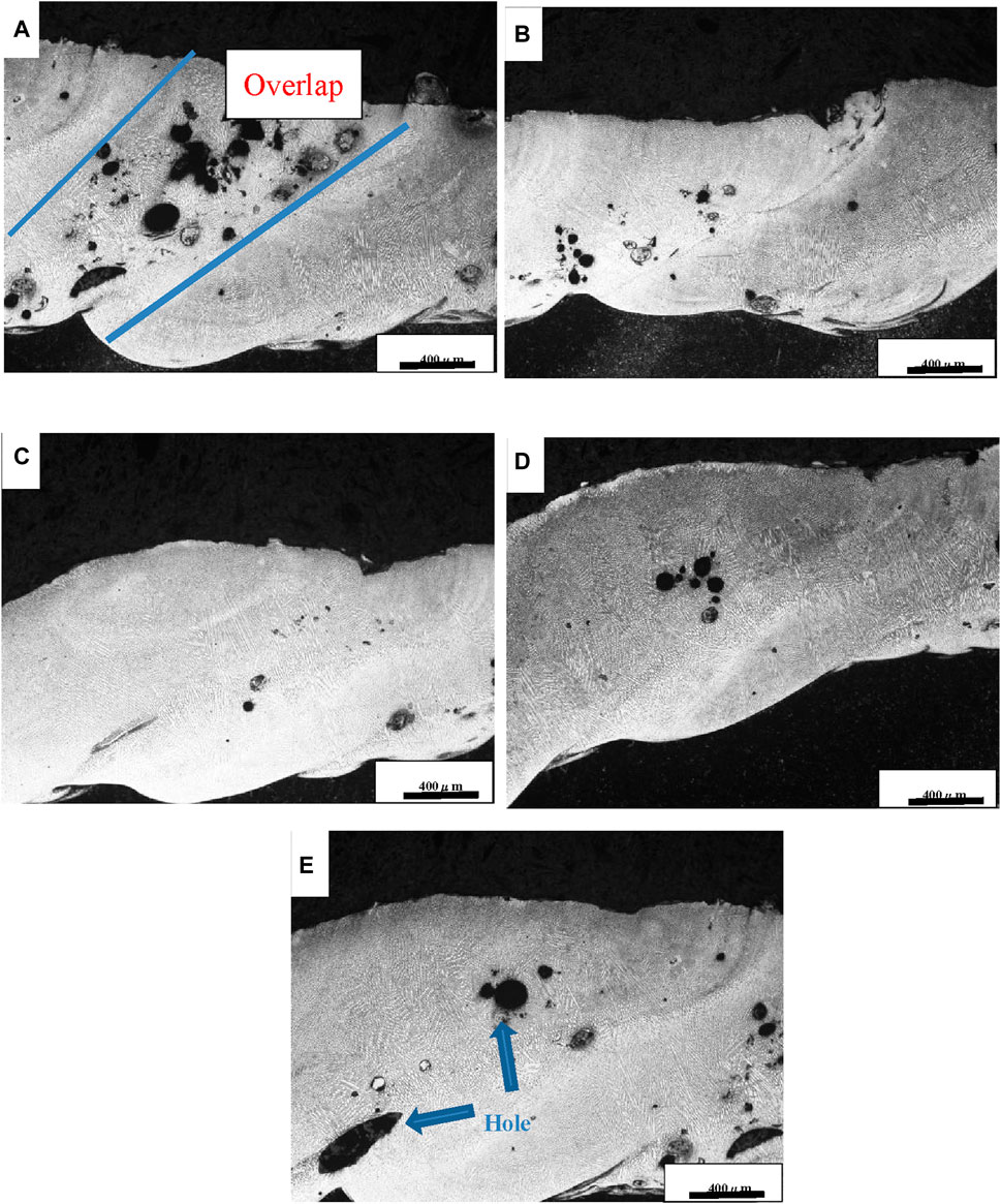
Figure 4. Microstructure of cladding layer at different overlapping rates: (A) 42%; (B) 44%; (C) 46%; (D) 48%; (E) 50% (By comparing the metallographic structure of coatings with different overlap rates, it was observed that the coating with a 46% overlap rate has the fewest structural defects.).
3.3 The influence of overlapping rate on the hardness of Fe-Ni-Ti composite cladding layer
Due to the tendency for defects to appear in the microstructure of the overlay zone in multi-pass fused coatings, the average microhardness is tested in the overlay area. This process results in a trend graph illustrating the microhardness variation with different overlap rates. As shown in Figure 5, the maximum microhardness of the Fe-Ni-Ti composite cladding layer reached 450 HV, which is 1.5 times the hardness of the Fe-36Ni Invar cladding layer and 2.2 times that of the base material, 45 steel. The results indicate a significant increase in microhardness for the Fe-Ni-Ti composite cladding layer compared to the Fe-36Ni Invar cladding layer. This enhancement is attributed to the Orowan strengthening and grain refinement as the primary strengthening mechanisms in the cladding layer (Xu et al., 2019). The in-situ formation of TiC in the cladding layer introduces relatively large strengthening phase particles, which are dispersed throughout the cladding layer’s microstructure. During stress, these particles are less susceptible to dislocation cutting, and the atomic arrangement of TiC differs from that of the base material. The incongruity in atomic alignment hinders dislocation motion, conferring the cladding layer with Orowan strengthening effects. Similar results were obtained by Xiaonan Mao and others in their research on TiC particle-reinforced titanium-based composite materials (Huang et al., 2019). Orowan strengthening is achieved by strengthening the properties of materials through dispersed particles and dislocations (Ma et al., 2014).
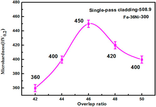
Figure 5. Microhardness of cladding layer at different overlapping rates (The microhardness of the coating with a 46% overlap rate is determined to be the highest based on the trend in hardness variation.).
As shown in Figure 5, when the overlap rate of laser cladding continuously changes, the microhardness of the overlap zone of Fe Ni Ti cladding coating also changes, with an overlap rate of 46%, which is the maximum microhardness of 450 HV. As the overlapping rate continues to increase, the hardness of the cladding layer in the overlapping area gradually decreases. When the overlapping rate reaches 50%, the microhardness of the cladding layer is 400 HV. Analysis: First, as the overlapping rate increases, the temperature in the overlapping area significantly rises, leads to an increase in undercooling and finer grain sizes, which leads to the effect of fine-grain strengthening and increased cladding layer hardness. In polycrystalline materials, the composition of grain boundaries has a pronounced hindrance effect on dislocation movement. Typically, the smaller the grain size, the larger the grain boundary area, and the more pronounced the strengthening effect on the material (Nes et al., 2005; Chokshi, 2020). The coating’s microstructure undergoes grain refinement, leading to an enhancement in the performance of the fused layer, in accordance with the strengthening principles of grain boundaries in polycrystalline materials. Second, as observed from the metallographic image in Figure 4, the initial stages of increasing the overlapping rate result in a reduction of defects in the overlapping area, which to some extent enhances the cladding layer’s hardness. However, when the overlapping rate becomes too high, the dilution rate of the cladding layer increases significantly, and some Ti elements are diluted into the base material. This reduces the in-situ formation of TiC strengthening phase particles in the cladding layer and prevents their uniform distribution in the γ-[Fe, Ni] solid solution matrix, weakening the dispersion strengthening. As a result, the cladding layer’s hardness decreases. Furthermore, the increase in the number of voids and cracks exacerbates the reduction in microhardness. The hardness of the multi-pass overlapping cladding layer is 11% lower than that of the single-pass cladding layer. This is primarily because, in multi-pass overlapping laser cladding, each subsequent cladding layer is affected by the heat from the previous layer. This causes the previous layers to undergo additional heating and cooling cycles, which affects the size and distribution of grains. Recrystallization or growth of grains can lead to a reduction in hardness.
3.4 The influence of overlapping rate on the friction coefficient of the Fe-Ni-Ti composite cladding layer
Figure 6 depicts the trend of friction coefficient changes in the 46% overlapping rate cladding layer during a 20-min period. In the figure, the black line represents changes in the friction coefficient, the yellow line represents variations in applied load, and the green line illustrates changes in friction force. As observed in Figure 6, as the applied load continuously increases, the frictional force acting on the cladding layer also rises. In the initial 4 min of increasing load, the friction coefficient curve exhibits significant fluctuations. This phenomenon can be attributed to impurity defects on the cladding layer’s surface and corresponds to the running-in phase of friction. However, after 4 min, even though the applied load continues to increase, the friction coefficient tends to stabilize. Upon data analysis, the average friction coefficient is calculated to be 0.412, which is significantly lower compared to the friction coefficient of the Fe-36Ni Invar alloy cladding layer. This improvement can be attributed to the uniform distribution of in-situ generated TiC intermetallic reinforcement phases on the γ-[Fe, Ni] solid solution, leading to a notable increase in the material’s wear resistance. This effect represents dispersion strengthening, significantly enhancing the cladding layer’s frictional performance (Feng et al., 2022; Wang et al., 2023).
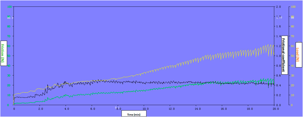
Figure 6. Variation trend of surface friction coefficient of cladding layer (The friction coefficient stabilizes after 4 min).
Figure 7 shows the surface friction coefficient trend of different overlap rates in the overlay coating. In the figure, the change in the average friction coefficient in the stable stage with the overlap rate is depicted. As the overlap rate changes, the friction coefficient of the cladding layer initially decreases, and when it reaches a certain value, it gradually increases. When the overlap rate increases from 42% to 46%, the friction coefficient gradually decreases. This is because, on one hand, the coating hardness increases, and, on the other hand, the coating structure becomes more uniform and dense. When the overlap rate reaches 46%, the friction coefficient reaches its minimum value of 0.412. When the overlap rate increases from 46% to 50%, the friction coefficient gradually increases to 0.459. The reason for this increase is that the higher overlap rate leads to more defects in the coating structure, and it is also influenced by the decrease in coating hardness (Pereira et al., 2015; Lian et al., 2018). The friction coefficient of a multi-pass cladding layer is increased by 5% compared to that of a single-pass cladding layer. This is mainly because the multi-pass overlay process increases surface roughness, introducing more textures and unevenness, which, in turn, increase the friction coefficient of the cladding layer.
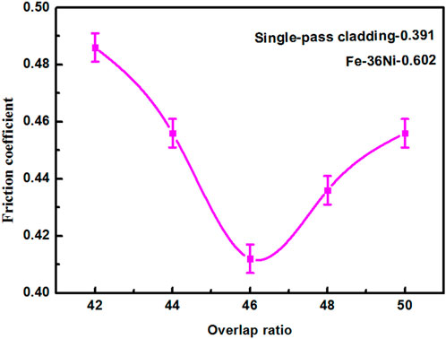
Figure 7. Friction coefficient of cladding layer at different overlapping rates (The friction coefficient of the coating with a 46% overlap rate is determined to be the lowest based on the trend in friction coefficient variation.).
3.5 The impact of overlap rate on the wear performance of Fe-Ni-Ti composite cladding layer
The significant influence of wear performance affects the application of fused coatings. The wear performance of fused coatings is studied by examining the percentage change in weight loss due to wear compared to the original weight of the coating. Figure 8 depicts the percentage change trends of fused coatings with different overlap rates. From the graph, it is evident that, as the overlap rate increases, the percentage of coating wear initially decreases and then rises. The lowest percentage of coating wear is observed at an overlap rate of 46%, with a percentage of 0.17%, which is 1.55 times lower than that of a single fusion pass. Analyzing the reasons, when the overlap rate is in the range of 42%–46%, the overlay coating exhibits more pores, cracks, and lower microhardness. During the friction tests, there is significant detachment and abrasion of larger abrasive grains at these defects, resulting in higher wear mass loss. At an overlap rate of 46%, the coating structure becomes denser, with fewer defects and higher hardness, leading to reduced wear mass loss. As the overlap rate continues to increase, the dilution rate of the coating becomes higher, the TiC reinforcement phase in the coating decreases, and defects become more prominent, leading to a decrease in coating wear performance (Guo et al., 2010; Huang et al., 2022). Multi-pass cladding layer exhibit higher residual stresses and more defects, resulting in greater wear mass loss compared to single-pass cladding layer.
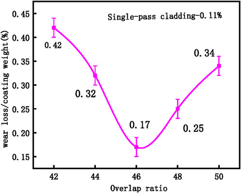
Figure 8. Percentage weight loss of fused coatings with different overlap rates (The wear performance of the coating with a 46% overlap rate is determined to be superior based on the percentage weight loss.).
Figure 9 is the wear morphology image of a 46% overlap rate overlay coating. It can be observed in the figure that the predominant wear in the cladding layer is adhesive wear (Tian et al., 2018). After loading, the frictional contact between the friction pair and the overlay coating surface results in relative sliding (Zhang and Chen, 2006; Aghababaei et al., 2016). During this sliding process, the attractive forces between the material surfaces cause the overlay coating to undergo surface adhesion, leading to the formation of ruptures and wear at the contact interface. When TiC particles from the overlay coating detach from one surface and transfer to another, they can create small, hard wear particles on the new surface. These particles further exacerbate wear, continuing to adhere and detach from other surfaces (Mishina and Hase, 2013; Molinari et al., 2018).
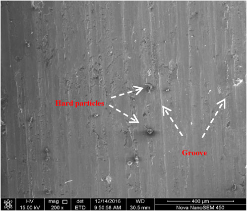
Figure 9. Wear performance of cladding layer (The primary wear mechanism of the fused coating is adhesive wear.).
4 Conclusion
This study investigates multi-pass laser cladding of Fe-Ni-Ti cladding layer on 45 steel and examines the influence of the overlap rate on the microstructure and properties of Fe-Ni-Ti cladding layer. The following conclusions are drawn:
(1) Laser cladding of Fe-Ni-Ti cladding layer on 45 steel results in a microstructure consisting of [Fe, Ni] austenite phase formed by Ni dissolution in γ-Fe, Fe0.64Ni0.36 solid solution, and in-situ generated TiC reinforcement phase at the fusion zone grain boundaries. With a bonding rate of 46%, the coating exhibits fewer defects and a uniform, dense microstructure.
(2) The effect of the overlap rate on the average microhardness of the cladding layer exhibits an initial increase followed by a decrease. When the overlap rate is 46%, the microhardness of the cladding layer reaches its highest value at 450 HV, which is 2.2 times that of the substrate. The hardness of the multi-pass cladding layer is 11% lower than that of the single-pass cladding layer.
(3) When the overlap rate is 46%, the friction coefficient of the cladding layer is at its lowest, measuring 0.412. At this overlap rate, the wear performance of the cladding layer is optimal, with a percentage weight loss of 0.17%. The friction coefficient of a multi-pass cladding layer is increased by 5% compared to that of a single-pass cladding layer. The wear theory of the cladding layer is mainly adhesive wear, which also includes abrasive wear.
Data availability statement
The original contributions presented in the study are included in the article/supplementary material, further inquiries can be directed to the corresponding author.
Author contributions
ZW: Conceptualization, Data curation, Methodology, Software, Writing–original draft. CQ: Investigation, Supervision, Visualization, Writing–review and editing. FZ: Software, Validation, Writing–review and editing.
Funding
The author(s) declare that financial support was received for the research, authorship, and/or publication of this article. This research was funded by the second batch of national level vocational education teacher innovation team research project (ZI2021090301).
Conflict of interest
The authors declare that the research was conducted in the absence of any commercial or financial relationships that could be construed as a potential conflict of interest.
Publisher’s note
All claims expressed in this article are solely those of the authors and do not necessarily represent those of their affiliated organizations, or those of the publisher, the editors and the reviewers. Any product that may be evaluated in this article, or claim that may be made by its manufacturer, is not guaranteed or endorsed by the publisher.
References
Aghababaei, R., Warner, D. H., and Molinari, J.-F. (2016). Critical length scale controls adhesive wear mechanisms. Nat. Commun. 7, 11816. doi:10.1038/ncomms11816
Cao, J., Liu, F., Lin, X., Huang, C., Chen, J., and Huang, W. (2013). Effect of overlap rate on recrystallization behaviors of Laser Solid Formed Inconel 718 superalloy. Opt. Laser Technol. 45, 228–235. doi:10.1016/j.optlastec.2012.06.043
Chen, C., Yin, J., Zhu, H., Xiao, Z., Zhang, L., and Zeng, X. (2019). Effect of overlap rate and pattern on residual stress in selective laser melting. Int. J. Mach. Tools Manuf. 145, 103433. doi:10.1016/j.ijmachtools.2019.103433
Chokshi, A. H. (2020). Grain boundary processes in strengthening, weakening, and superplasticity. Adv. Eng. Mater 22, 1900748. doi:10.1002/adem.201900748
Feng, Y., Gao, Z., and Hu, Z. (2022). Influence of annealing treatment on microstructure and properties of Ni-rich NiTi alloy coating prepared by laser cladding. Materials 15, 3298. doi:10.3390/ma15093298
Fu, F., Zhang, Y., Chang, G., and Dai, J. (2016). Analysis on the physical mechanism of laser cladding crack and its influence factors. Optik 127, 200–202. doi:10.1016/j.ijleo.2015.10.043
Gong, N., Meng, T. L., Cao, J., Wang, Y., Karyappa, R., Ivan Tan, C. K., et al. (2023). Laser-cladding of high entropy alloy coatings: an overview. Mater. Technol. 38, 2151696. doi:10.1080/10667857.2022.2151696
Guo, C., Zhou, J., Zhao, J., and Chen, J. (2010). Effect of ZrB 2 on the microstructure and wear resistance of Ni-based composite coating produced on pure Ti by laser cladding. Tribol. Trans. 54, 80–86. doi:10.1080/10402004.2010.519860
Huang, X., Gao, Y., Wang, Z., Yi, Y., and Wang, Y. (2019). Microstructure, mechanical properties and strengthening mechanisms of in-situ prepared (Ti5Si3 + TiC0.67)/TC4 composites. J. Alloys Compd. 792, 907–917. doi:10.1016/j.jallcom.2019.04.056
Huang, Y., Hu, Y., Zhang, M., Mao, C., Tong, Y., Zhang, J., et al. (2022). On the enhanced wear resistance of laser-clad CoCrCuFeNiTix high-entropy alloy coatings at elevated temperature. Tribol. Int. 174, 107767. doi:10.1016/j.triboint.2022.107767
Li, Y., and Ma, J. (1997). Study on overlapping in the laser cladding process. Surf. Coatings Technol. 90, 1–5. doi:10.1016/S0257-8972(96)03022-8
Lian, G., Yao, M., Zhang, Y., and Huang, X. (2018). Analysis and respond surface methodology modeling on property and performance of two-dimensional gradient material laser cladding on die-cutting tool. Materials 11, 2052. doi:10.3390/ma11102052
Ma, K., Wen, H., Hu, T., Topping, T. D., Isheim, D., Seidman, D. N., et al. (2014). Mechanical behavior and strengthening mechanisms in ultrafine grain precipitation-strengthened aluminum alloy. Acta Mater. 62, 141–155. doi:10.1016/j.actamat.2013.09.042
Manoj, A., Saurabh, A., Narala, S. K. R., Saravanan, P., Natu, H. P., and Verma, P. C. (2023). Surface modification of grey cast iron by laser cladding for automotive brake disc application. Wear 532, 205099–205533. doi:10.1016/j.wear.2023.205099doi:205099
Mishina, H., and Hase, A. (2013). Wear equation for adhesive wear established through elementary process of wear. Wear 308, 186–192. doi:10.1016/j.wear.2013.06.016
Molinari, J.-F., Aghababaei, R., Brink, T., Frérot, L., and Milanese, E. (2018). Adhesive wear mechanisms uncovered by atomistic simulations. Friction 6, 245–259. doi:10.1007/s40544-018-0234-6
Nes, E., Holmedal, B., Evangelista, E., and Marthinsen, K. (2005). Modelling grain boundary strengthening in ultra-fine grained aluminum alloys. Mater. Sci. Eng. A 410 (411), 178–182. doi:10.1016/j.msea.2005.08.121
Penelle, R., and Baudin, T. (2010). Primary recrystallization of invar, Fe-36%Ni alloy: origin and development of the cubic texture. Adv. Eng. Mater 12, 1047–1052. doi:10.1002/adem.201000077
Pereira, J., Zambrano, J., Licausi, M., Tobar, M., and Amigó, V. (2015). Tribology and high temperature friction wear behavior of MCrAlY laser cladding coatings on stainless steel. Wear 330, 280–287. doi:10.1016/j.wear.2015.01.048
Shiga, M. (1996). Invar alloys. Curr. Opin. Solid State Mater. Sci. 1, 340–348. doi:10.1016/S1359-0286(96)80023-4
Tian, H., Wang, C., Guo, M., Tang, Z., Wei, S., and Xu, B. (2018). Frictional wear performance under oil-lubricated conditions and wear resistance mechanism of high-velocity arc-sprayed FeNiCrAl coating. Surf. Coatings Technol. 353, 237–246. doi:10.1016/j.surfcoat.2018.08.060
Vinogradov, A., Hashimoto, S., and Kopylov, V. I. (2003). Enhanced strength and fatigue life of ultra-fine grain Fe–36Ni Invar alloy. Mater. Sci. Eng. A 355, 277–285. doi:10.1016/S0921-5093(03)00082-0
Wang, Z., Gui, W., Fu, J., Zhu, P., and Lu, Y. (2023). Microstructure and properties of electromagnetic field-assisted laser-clad Norem02 iron-based cemented carbide coating. Materials 16, 6774. doi:10.3390/ma16206774
Wegener, T., Brenne, F., Fischer, A., Möller, T., Hauck, C., Auernhammer, S., et al. (2021). On the structural integrity of Fe-36Ni Invar alloy processed by selective laser melting. Addit. Manuf. 37, 101603. doi:10.1016/j.addma.2020.101603
Xu, S., Zhou, Z., Long, F., Jia, H., Guo, N., Yao, Z., et al. (2019). Combination of back stress strengthening and Orowan strengthening in bimodal structured Fe–9Cr–Al ODS steel with high Al addition. Mater. Sci. Eng. A 739, 45–52. doi:10.1016/j.msea.2018.09.111
Xv, Y., Sun, Y., Cheng, W., and Zhang, Y. (2023). Engineering process optimization and quality stability control of high-speed laser cladding coatings based on AHP-FCE. Coatings 13, 1806. doi:10.3390/coatings13101806
Zhan, X., Qi, C., Gao, Z., Tian, D., and Wang, Z. (2019). The influence of heat input on microstructure and porosity during laser cladding of Invar alloy. Opt. Laser Technol. 113, 453–461. doi:10.1016/j.optlastec.2019.01.015
Zhang, Z., and Chen, D. (2006). Consideration of Orowan strengthening effect in particulate-reinforced metal matrix nanocomposites: a model for predicting their yield strength. Scr. Mater. 54, 1321–1326. doi:10.1016/j.scriptamat.2005.12.017
Zhao, L., Zhao, M.-J., Li, D.-Y., Zhang, J., and Xiong, G.-Y. (2012). Study on Fe–Al–Si in situ composite coating fabricated by laser cladding. Appl. Surf. Sci. 258, 3368–3372. doi:10.1016/j.apsusc.2011.09.057
Zhou, S., Zeng, X., Hu, Q., and Huang, Y. (2008). Analysis of crack behavior for Ni-based WC composite coatings by laser cladding and crack-free realization. Appl. Surf. Sci. 255, 1646–1653. doi:10.1016/j.apsusc.2008.04.003
Keywords: laser cladding, overlay rate, FeNiTi, microstructure, wear resistance
Citation: Wang Z, Qi C and Zhang F (2024) The overlap rate influences the microstructure and properties of laser-cladded Fe-Ni-Ti composite coatings. Front. Mater. 11:1342926. doi: 10.3389/fmats.2024.1342926
Received: 22 November 2023; Accepted: 18 March 2024;
Published: 04 April 2024.
Edited by:
Essam Moustafa, King Abdulaziz University, Saudi ArabiaReviewed by:
Guangming Cheng, Princeton University, United StatesLakshmi Narayan Ramasubramanian, Indian Institute of Technology Delhi, India
Copyright © 2024 Wang, Qi and Zhang. This is an open-access article distributed under the terms of the Creative Commons Attribution License (CC BY). The use, distribution or reproduction in other forums is permitted, provided the original author(s) and the copyright owner(s) are credited and that the original publication in this journal is cited, in accordance with accepted academic practice. No use, distribution or reproduction is permitted which does not comply with these terms.
*Correspondence: Zhen Wang, MTcxNUBzZHAuZWR1LmNu