 Aihemaiti Kayishaer1,2
 Claire Magnenet1Ileana-Alexandra Pavel1Hamdi Ben Halima1Virginie Moutarlier1
 Boris Lakard1Nathalie Redon2
 Caroline Duc2
 Sophie Lakard1*
- 1Université de Franche-Comté, UTINAM, UMR CNRS 6213, Besançon, France
- 2Center for Energy and Environment, IMT Nord Europe, Institut Mines-Télécom, University of Lille, Lille, France
The electrodeposition of polyaniline films is usually carried out in acid solutions such as hydrochloric acid, perchloric acid or sulfuric acid, and more rarely in organic acids such as camphorsulfonic acid (CSA). In this study, the impact of the presence of a surfactant in the electrolytic solution based on hydrochloric acid or CSA was evaluated by successively using anionic (sodium dodecyl sulfate, SDS), cationic (cetyltrimethylammonium bromide, CTAB), and non-ionic (Tritonx100) surfactants. Whatever the surfactant and the acid used, the electrochemical oxidation of aniline has successfully led to the formation of a thick polyaniline (PANI) film through a quasi-reversible reaction controlled by the diffusion of aniline monomers. The nature of the surfactant was shown to affect physico-chemical properties of the film, in particular its morphological features (morphology, thickness, roughness), electrochemical activity, specific capacitance, and conductivity. For example, PANI films containing SDS had a spongy morphology when PANI films containing Tritonx100 had a more fibrous and compact structure. Glow Discharge Optical Emission Spectroscopy (GDOES) experiments also highlighted differences depending on the acid used since chloride anions, from HCl, were present only on the top surface of the PANI films when camphorsulfonate anions were present everywhere throughout the polymer film, which impacts the doping process and electrochemical activity of the films. Moreover, the specific capacitance of the PANI/CSA films is higher and more sensitive to current density variation than the one of PANI/HCl films. Finally, electrochemical impedance experiments evidenced that the conductivity of PANI films electrodeposited from CSA solutions was much higher than the one of PANI films prepared from HCl solutions, and highly dependent on the nature of the surfactant, the most conductive films being obtained in the presence of SDS and Tritonx100. Therefore, the originality of this work comes from the possibility of modulating the conductivity, capacitance and electroactivity of electrodeposited polyaniline films using surfactants of different polarity, and from the determination of the distribution of ions in the films using the GDOES technique, which is rarely used to characterise organic films.
1 Introduction
Conducting polymers are defined as polymeric materials that can provide electrical conductivity after appropriate doping procedure, in addition to being processable, lightweight, and not expensive (Wu et al., 2019). Polyaniline (PANI) is one of the most widely used conducting polymers due to its remarkable optical and electrochemical properties (Cho et al., 2019), good environmental and chemical stability (Chandrakanthi and Careem, 2000; Ji et al., 2020), and facile redox and pH switching between different oxidation states (Xie et al., 2016). Thus, polyaniline has been used in various areas like anticorrosion coatings (Deshpande et al., 2014; Bazli et al., 2020; Gao et al., 2021), biomedical applications (Zare et al., 2019; Pina and Falletta, 2022), removal of pollutants (Zare et al., 2018; Samadi et al., 2021), supercapacitors (Eftekhari et al., 2017a; Liu et al., 2019), electrochromism (Celiesiute et al., 2019; Liu et al., 2022), organic electronics (Garai et al., 2010), and gas sensors (Zhang et al., 2019; Kumar et al., 2020). Polyaniline is usually synthesized via oxidative coupling of aniline monomers using chemical or electrochemical routes. Following the first route, chemical oxidants, such as ferric chloride or ammonium persulfate, are applied to oxidize the monomer (Jaymand, 2013; Liao et al., 2019), while on the second route the monomers are oxidized electrochemically (Motheo et al., 1998; Wang and Levon, 2012; Ashokan et al., 2015; Xing et al., 2017). The electrochemical approach is undoubtedly the most convenient and simplest one for obtaining PANI films with a controlled thickness. The properties of the electrodeposited PANI films are greatly influenced by the nature of the dopant (Wang and Levon, 2012; Xing et al., 2017) and the acid (Motheo et al., 1998; Ashokan et al., 2015), both known to significantly affect the growth, morphology, electroactivity, and conductivity of the polymer.
Before performing the electrodeposition of PANI films, it is already necessary to solubilize the aniline properly, which is not always easy in aqueous media. Thus, copolymers of aniline with derivatives containing sulfonic groups, such as poly (aniline-co-amino-naphthol-sulfonic acid) (Bhandari et al., 2010) and poly (aniline-co-amino-hydroxy-naphtalene-1-sulfonic acid) (Bhandari et al., 2011), were found to improve solubility and corrosion protection efficiency. Highly soluble polyaniline was also obtained by sulfonation of polyaniline (Routh et al., 2011), or by grafting of polyaniline with polyethylene glycol and β-cyclodextrine (Maity et al., 2018). The use of organic acids with sulfonic groups such as camphorsulfonic acid (CSA), dodecylbenzenesulfonic acid or para-toluenesulfonic acid also allow to considerably improve the solubility of aniline (Wu et al., 2014; Liao et al., 2019). Furthermore, these sulfonic acids can act both as a dopant and as a surfactant for PANI films (Olinga et al., 2000). Thus, CSA has been used as a surfactant and dopant of PANI/MWCNTs nanocomposites deposited on graphite foil and Ni foam which showed high specific capacitances and energy densities while having remarkable cycling stability (Awata et al., 2020). In addition, the optimal conditions for the doping process of polyaniline with CSA were determined, to obtain a material that can be used as conductive fillers for lightning protection coatings in a study by Krukiewicz and Katunin (2016).
The use of a surfactant in the electrolytic solution can also significantly modify the morphology, conjugation, doping degree, and conductivity of the resultant polymer films (Wu et al., 2012). Moreover, an anionic surfactant also acts as a dopant and leads to micelle/emulsion polymerization because it can form micelles in aqueous solution by the aid of the hydrophobic alkyl chain and the hydrophilic ionic charge. For example, Manne and Gaub (1995) demonstrated that surfactants could aggregate at solid surfaces to form surprising structures, such as nanoscale half-cylinders. Similarly, Jamdegni and Kaur (2020) showed that the combined presence of surfactants and monomers in a para-toluenesulfonic acid solution could result in the formation of supramolecular micelles whose shape strongly impacts that of electrodeposited polymers to lead to very different structures such as aggregated spheres, ellipses, or interconnected wires. Thus, several surfactants have been used previously to synthesize conducting polymer films with various morphologies and sizes. The most frequently used surfactant is sodium dodecyl sulfate (SDS). Indeed, polyaniline films have been electropolymerized in the presence of this anionic surfactant for incorporation in dye-sensitized solar cells leading to remarkable power conversion efficiency (Qiu et al., 2014), and in potentiometric biosensors, allowing the detection of urea with an enhanced sensitivity due to an increased enzyme loading and faster diffusion of substrates in the porous polymer film (Kanungo et al., 2002). Also, an electrode modified by electropolymerization of a solution composed of aniline, H2SO4 and SDS showed improved specific capacitance and cycling stability due to its dispersed morphology, making it promising for supercapacitor applications (Zhou et al., 2019). Other surfactants can be chosen to obtain PANI films. Thus, a cholesterol biosensor has been fabricated by covalently coupling cholesterol oxidase via glutaraldehyde onto electrochemically prepared polyaniline film in presence of Tritonx100, a non-ionic surfactant. This biosensor exhibited a low detection limit and a high sensitivity (Khan et al., 2009). PANI films have also been prepared on a mild steel surface from aniline solutions containing different concentrations of Tween80 surfactant. The presence of Tween80 led to the inhibition of the oxidation of steel and to an increase of the protection efficiency of the polymer film to the corrosion of steel (Abd-El-Nabey et al., 2016). Well-defined PANI rhombic plates have been produced using CTAB as cationic surfactant in low acid environment. They exhibited water dispersibility, processability, and flow-induced colour variation, which was attributed to the intermolecular interactions between residual CTAB molecules and PANI molecules (Ma et al., 2017).
Through these reports, it is axiomatic that the introduction of a surfactant in the electrolytic solution has a great influence on the properties of the electrodeposited polymers. However, there is little work in the literature dedicated to the study and comparison of PANI films obtained from different surfactants. Thus, the two major studies in the field were conducted by Raj et al. (2010) and Jamdegni and Kaur (2020). In the first one, electropolymerization of aniline was carried out in micellar solutions of CSA, CTAB, and Tritonx100 to reveal the morphology against the nature of the surfactant molecule (Raj et al., 2010). Indeed, PANI films electrosynthesized from solutions composed of CSA or Tritonx100, aniline and perchloric acid showed uniform nanosized globular structures on glassy carbon electrode and indium tin oxide glass. In the second one, the effect of the polarity of surfactant head on the shape and size of PANI structures was demonstrated as well as their influence on the electrochemical and electrochromic properties of the PANI films (Jamdegni and Kaur, 2020).
To complete these studies and to obtain additional information on the impact of surfactants on the properties of electrodeposited polyaniline films, we prepared different PANI films with either a strong mineral acid, HCl, or an organic acid, camphorsulfonic acid. These acids were coupled with surfactants of different charge (Figure 1), then the physico-chemical properties of the PANI films were characterized and compared.

FIGURE 1. The different surfactants investigated in this study.
2 Materials and methods
2.1 Materials and reagents
Aniline (>99.5%, Acros Organic), sodium dodecyl sulfate (>99%, Acros Organic, SDS), cetyltrimethylammonium bromide (>99%, Acros Organic, CTAB), Tritonx100 (Acros Organic, Tritonx100), camphorsulfonic acid (>99%, Aldrich, CSA), and hydrochloric acid (37%, VWR Chemicals, HCl) were used without prior treatment. The water used in all the experiments was de-ionized water from a Synergy® Water Purification System.
2.2 Electrochemical deposition of polymer films
All electrochemical experiments were performed using a SPELEC potentiostat/galvanostat, controlled by a PC via DropView software interface. The electrochemical cell consists of a classical three-electrode setup with a Saturated Calomel Electrode (SCE) as the reference electrode, a platinum plate (5 × 5 × 0.1 cm) as the counter-electrode, and a platinum wire (0.785 mm2) or fluorine-doped tin oxide (FTO) substrate (R = 80 Ω/square, 15 mm × 30 mm) as the working electrode.
The electrolyte used for electropolymerization was composed of an aqueous solution of 0.4 M aniline and HCl or CSA acid (1.2 M since a low pH is needed for preparation of the conductive polyaniline) which were used either alone or with a surfactant. For the surfactant-assisted synthesis, the surfactant (SDS, CTAB, or Tritonx100) was added to the electrolytic solution at a concentration of 0.01 M. The PANI films were electropolymerized either by cyclic voltammetry on a platinum working electrode in a potential range of −0.2 to +1.75 V/SCE with a scan rate of 50 mV/s to study their electrochemical behavior, or by chronoamperometry at a potential of +1.25 V/SCE for 5 min on a transparent planar FTO electrode since this substrate is convenient for carrying out physico-chemical characterizations.
2.3 Characterization techniques
2.3.1 Mechanical profilometry
The thickness and roughness of each polymer film were measured using a Dektak 150 Surface Profiler from Veeco. Arithmetic roughness was measured on a scan length of 10 mm at a scan speed of 50 μm/s. The thickness of each film was measured under the same operating conditions after the creation of a physical sharp step in the film. The thickness and roughness values reported are the average of at least 3 measurements done at different locations in the samples. Considering the dispersion of the values obtained, the uncertainty of the average film thickness can be estimated at 10% of the mean value. The uncertainty of roughness measurements is lower, as 3 measurements are taken over a large distance of 10 mm, reducing the uncertainty to less than 5% of the mean value.
2.3.2 SEM microscopy
The surface topography of each polymer film was obtained, without prior metallization, using a high-resolution SEM microscope Quanta 450 W from FEI. The electron beam energy used was 10 keV and the working distance used was 10 mm.
2.3.3 GDOES-profiler
A Glow Discharge Optical Emission Spectrometer (Model Jobin Yvon HORIBA GD Profiler) was used since GDOES spectroscopy is an analytical technique that provides ultra-fast elemental depth profile analysis of materials. During operation, plasma was generated in analysis chamber by applying a voltage between the anode and the cathode (the sample) in presence of argon under low pressure. Ionized Ar atoms caused sputtering of sample area. Sputtered atoms excited in plasma rapidly de-excited by emitting photons with characteristic wavelengths. A moderate power (10W) was applied to improve depth resolution. The detected elements were C (156 nm), O (130 nm), Si (288 nm), Cl (134 nm), S (180 nm), and Sn (317 nm).
2.3.4 Electrochemical characterizations
Once the platinum working electrode is coated with a film of PANI by electrochemical oxidation, it is rinsed and then immersed in a solution containing the acid (HCl or CSA at 1.2 M) and possibly the surfactant (0.01 M) used during electrosynthesis. Post-polymerization CVs are then carried out which consist of performing 5 potential scans in a potential range going from −0.2 to +1.75 V/SCE (scan speed: 50 mV/s). The electrochemical activity is then deduced from the evolution of the oxidation/reduction processes appearing in the resulting CVs. Other cyclic voltammetry experiments were also carried out at different scan speeds (10, 15, 20, 30, and 35 mV/s) in monomer-free solutions (acid or acid + surfactant) to determine if the electrochemical process on the PANI-modified electrode is controlled by diffusion. Galvanostatic charge-discharge tests were performed at different current densities (1.0, 1.1, 1.2, 1.3, 1.4, and 1.5 mA/cm2) in the potential range going from 0 to +0.75 V/SCE since this potential window includes the redox peaks associated to the leucoemeraldine/emeraldine transition.
2.3.5 Electrochemical impedance spectroscopy (EIS)
EIS measurements were carried out using an electrochemical cell consisting of three electrodes. The reference electrode was a saturated calomel electrode, the auxiliary electrode was a platinum sheet and the polyaniline-modified FTO substrates were used as working electrode. Since the use of ferricyanide/ferrocyanide ions as redox mediator system is known to improve the sensitivity of EIS measurements (Lee et al., 2021; Sanchez-Amaya et al., 2022), EIS measurements were carried out in the presence of the redox probe [Fe(CN)6]3−/[Fe(CN)6]4− at 5 mM in PBS buffer at pH 7.4, with a frequency ranged from 100 kHz to 1 Hz, two frequency points per frequency decade, and using a modulation voltage of 50 mV (Eac). During the measurements, the potential was kept at +0.5 V/SCE (Edc). Data fitting on EIS spectra was performed with Randomize (5,000 iterations) + Simplex method (fit stopped on 5,000 iterations) and using the following equivalent circuit model [Rs + Q/Rct] where Rs is the electrolyte solution’s resistance {[Fe(CN)6]3−/4− at 5 mM in PBS buffer at pH7.4}, Q is the parallel element (the coefficient of the constant phase element), and Rct is the charge transfer resistance.
3 Results and discussion
3.1 Electropolymerization of aniline in HCl or CSA solution in the presence of surfactants
The electropolymerization of aniline is first performed in a surfactant-free solution of HCl, then in HCl solutions containing either a cationic, anionic, or neutral surfactant (Figure 1) to clarify the impact of those additives on PANI properties. SDS, which contains a negative hydrophilic head along with a 12 carbon long hydrophobic chain is used as anionic surfactant while CTAB, which contains a positive hydrophilic head and a 16 carbon long hydrophobic chain, is used as cationic surfactant. Tritonx100, having a hydrophilic polyethylene oxide chain with neutral aromatic hydrophobic head, is used as non-ionic surfactant.
A surfactant-free HCl solution containing aniline monomers is oxidized in a potential range from −0.2 to +1.75 V/SCE using cyclic voltammetry (CV). The first scan is shown in Figure 2A while the following scans are given in Supplementary File S1. During the first potential scan, an anodic peak corresponding to the oxidation of the aniline monomers and the initiation of the electropolymerization reaction appears at +0.95 V/SCE. In the following scans (Supplementary File S1), the redox peak current increases progressively with the number of potential scans indicating that the growing polymer film is conductive but also that the electropolymerization of aniline is an autocatalytic process as shown by Mu and Kan (1996). Moreover, a first oxidation peak at +0.20 V/SCE corresponding to the transition from the leucoemeraldine form into the emeraldine form (Holze and Nalwa, 2000), a second oxidation peak at +0.45 V/SCE due to the redox process of the degradation products of PANI at high anodic potentials (Baba et al., 2004; Wu et al., 2018), and a third oxidation peak at +0.75 V/SCE corresponding to the transition from the emeraldine form into the pernigraniline form, followed by two reduction peaks corresponding to the return to the initial leucoemeraldine form are visible (Holze and Nalwa, 2000). At the end of the CV, a green deposit of PANI/HCl is visible on the surface of the electrode.
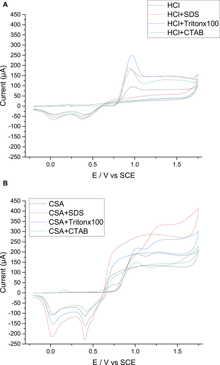
FIGURE 2. Potentiodynamic growth of polyaniline films grown in HCl (A) or CSA (B) with different surfactants or in the absence of surfactant. Scan speed: 50 mV s−1. WE: Pt.
The cyclic voltammetries obtained in aniline and HCl solution in the presence of SDS, CTAB or Tritonx100 have a very similar shape since they all show a main oxidation peak at +0.95 V/SCE and two reduction peaks at +0.40 and +0.05 V/SCE (Figure 2A; Supplementary File S2). They are also comparable to those obtained from surfactant-free solutions of HCl. Only the intensity of the oxidation and reduction peaks varies from one surfactant to the other, the intensity being the highest during the growth of PANI/HCl + Tritonx100 (Figure 2A). It is also noticeable that the lowest peak intensity is obtained for the PANI/HCl film prepared in the absence of surfactant in the electrolyte, thus the electropolymerization reaction seems easier in the presence of a surfactant whatever its charge. At the end, a green deposit is obtained on the working electrode in all cases, showing that aniline can be successfully polymerized with a positive, negative, or neutral surfactant.
While the oxidation of aniline in CSA solutions with or without surfactant leads to the formation of a green PANI film visible to the naked eye and comparable to that obtained with HCl solutions, the CVs obtained in CSA solutions (Figure 2B) differ markedly from those previously obtained in HCl solutions. Indeed, if the aniline oxidation peaks appear at potentials of +0.95 to +1.0 V/SCE in the presence of Tritonx100 and CTAB or in the absence of surfactant, the peaks are however much wider than in HCl solutions. In fact, the higher size of the CSA anion may lead to a slower diffusion of the anion in both the electrolyte and the polymer film and to a breaking of the size-dependent interactions inside the film, and thus it can slow down monomer and polymer oxidation leading to a wider oxidation peak (Abd-Elwahed and Holze, 2002).
In addition, the aniline oxidation peak observed during the first scan in the presence of SDS is particularly broad and is present at a higher potential, +1.3 V/SCE, which may be due to the presence of sulfonate groups in both SDS and CSA possibly leading to repulsive interactions between negative charges. On the contrary, the shape of the following potential scans is similar to that obtained in HCl solutions since all oxidation and reduction peaks characteristic of polyaniline growth are present and their peak current increases progressively with the number of potential scans indicating that the growing PANI film is conductive (Supplementary Files S3, S4).
The effect of scan rate on the cycling voltammograms was then studied to determine the mode limiting aniline monomer transport to the FTO working electrode in HCl or CSA solutions with different surfactants or in the absence of surfactant. For each electrolyte composition, the cyclic voltammograms were performed for the five scan rates: 10, 15, 20, 30, and 35 mV/s. Then, the evolution of the anodic peak intensity corresponding to the emeraldine/pernigraniline redox pair with the square root of the scan rate was drawn (Figure 3). Since Ip was proportional to v1/2, whatever the acid and the surfactant used, it can be assumed that the electrochemical process follows the Randles-Sevcik equation (Eq. 1), which means that the electrochemical process on the electrode is controlled by a solid-state diffusion process (Inamdar et al., 2011).
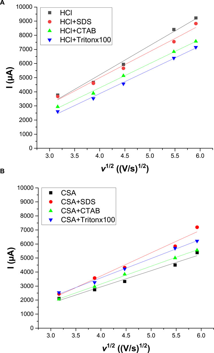
FIGURE 3. Variation of the anodic peak current as a function of the square root of the scan rate. Cyclic voltammograms were performed either in HCl (A) or CSA (B) solutions with different surfactants or in the absence of surfactant. Scan speed: 50 mV s−1. WE: Pt.
Where Ip is the peak current, n is the number of electrons transferred in unit reaction, A is the area of the electrode, C is the concentration, D is the diffusion coefficient, and v is the scan rate.
Moreover, the slope of straight line Ip–v1/2 directly reflected the diffusion coefficient of the electrolyte on the polyaniline film-modified electrode. By comparison, it appeared that the slopes were higher in HCl solutions [varying from 1,685 to 2017 µA/(V/s)1/2] than in CSA solutions [varying from 1,158 to 1,644 µA/(V/s)1/2]. As a result, the electropolymerization of PANI on the FTO substrate can be considered as a quasi-reversible reaction controlled by the diffusion of aniline monomers both in the presence or in the absence of surfactant in the HCl or CSA solution. Moreover, the higher size of the camphorsulfonate anions compared to the chloride anions led to a slower diffusion of the anions in both the electrolyte and the polymer films as previously shown using computational chemistry calculations (Lee et al., 2009) and electrochemical experiments (Abd-Elwahed and Holze, 2002).
3.2 Morphological features of the electrodeposited polyaniline films
The morphological features of polyaniline films electrodeposited with or without surfactant on FTO planar electrodes were first studied using SEM microscopy. SEM pictures show that the PANI film electrodeposited in a surfactant-free HCl solution has a sponge-like morphology (Figure 4A) similar to the one generally observed (Kovac et al., 2022). PANI/HCl + SDS (Figure 4B) and PANI/HCl + CTAB (Figure 4D) films have a similar but even more spongy structure while the structure of PANI/HCl + Tritonx100 (Figure 4C) is different, possibly due to the larger size of the surfactant or the use of a non-ionic surfactant, which leads to the absence of repulsive interactions inside the film (Figure 4). Also, the thickness of the PANI/HCl + SDS film can be estimated to 15 µm which is lower than the one of the other PANI/HCl films (PANI/HCl: 40 μm, PANI/HCl + Tritonx100: 34 μm, PANI/HCl + CTAB: 31 µm). All PANI films have a low roughness of 0.3 µm for PANI/HCl, 0.2 µm for PANI/HCl + SDS, 0.1 µm for PANI/Tritonx100 and PANI/HCl + CTAB. The lower thickness of the PANI/HCl + SDS film is probably due to the high size of SDS anions which are attracted by positively charged oxidized PANI films and causes steric hindrance unfavourable to the growth of the PANI film. The same trend was previously observed for polypyrrole films, since their thickness was higher when doped with small ions such as perchlorates than when doped with large ions such as para-toluenesulfonates or camphorsulfonates (Patois et al., 2011).
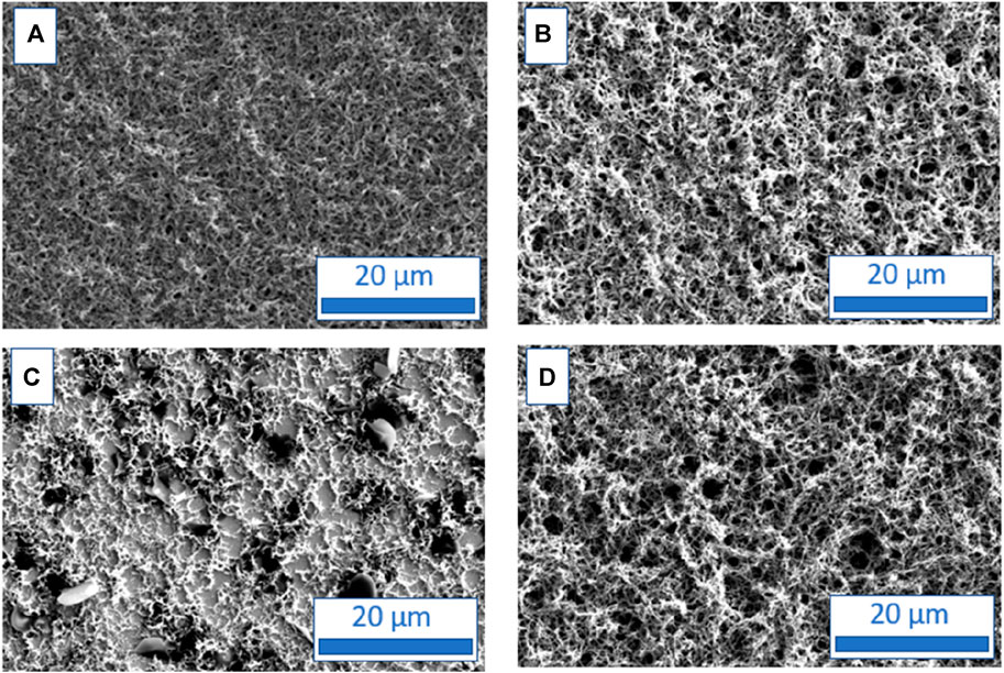
FIGURE 4. SEM micrographs of polyaniline films grown in HCl solutions containing no surfactant (A), SDS (B), Tritonx100 (C), or CTAB (D) at 0.01 M.
SEM images of the PANI films prepared from CSA solutions were also done for comparison. These pictures show different structures for PANI films depending on the Figure 4A surfactant used (Figure 5). The morphology of the PANI/CSA + SDS (Figure 5B) film has a spongy structure (Figure 5B) similar to the ones of the PANI films grown in HCl solutions (Figure 4). On the contrary, the PANI/CSA + CTAB (Figure 5D) or PANI/CSA + Tritonx100 (Figure 5C) have a different structure, less spongy, more compact, fibrous, and comparable to that obtained from CSA solutions in the absence of surfactant (Figure 5A) but very different from those obtained in HCl solutions.
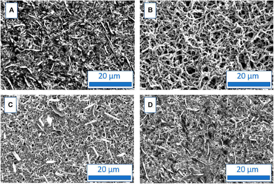
FIGURE 5. SEM micrographs of polyaniline films grown in CSA solutions containing no surfactant (A), SDS (B), Tritonx100 (C), or CTAB (D) at 0.01 M.
The difference in morphology between PANI films electrodeposited in HCl or CSA solutions and in the presence of surfactants is not very surprising. Indeed, Giz et al. (2000) have already demonstrated through AFM images that the use of different dopants induces changes in surface morphology which are due to several factors involved in the electropolymerization process, such as anion diffusion/migration in the polymer matrix, salt solubility, and, specifically, the chemical nature of the anion (Sizun et al., 2012). The thickest PANI films are PANI/CSA + SDS (35 µm) and PANI/CSA (thickness: 30 µm), whose thicknesses are comparable with those of PANI/HCl, PANI/HCl + Tritonx100 and PANI/HCl + CTAB. One possible explanation of the highest thickness of PANI/CSA + SDS could be the presence of sulfonates both in the acid and in the surfactant which could lead to a particular affinity facilitating the growth of the polymer film. On the contrary, the films grown in CSA and CTAB or Tritonx100 have a lower thickness (27 µm for PANI/CSA + CTAB and 16 µm for PANI/CSA + Tritonx100) than PANI/CSA films. With a roughness between 0.2 and 0.5 µm whatever the electrolyte used, the PANI films deposited from CSA solutions present similar roughness than PANI films from HCl solutions.
3.3 Location of the anions in the electrodeposited polyaniline films
GDOES experiments were carried out to determine the location of anions in polyaniline films since this characterization technique provides a signal from each chemical element as a function of erosion time, thus allowing to access the distribution of the chemical elements in the film (Giz et al., 2000; Xiao et al., 2013). Thus, the qualitative GDOES depth profiles of PANI films are followed by the carbon element and FTO substrate by silicon element (Figure 6). PANI/FTO interface could be located by the decrease of carbon signal and increase of the silicon signal. The accumulation of carbon at the interface is due to the modification of the sputtering rate between the polymer and the FTO substrate and C peaks observed at the beginning of the sputtering (during the first seconds) are not meaningful since they are probably due to surface contamination. GDOES technique allows us to determine the distribution of counter-anions within electrodeposited polymer films.
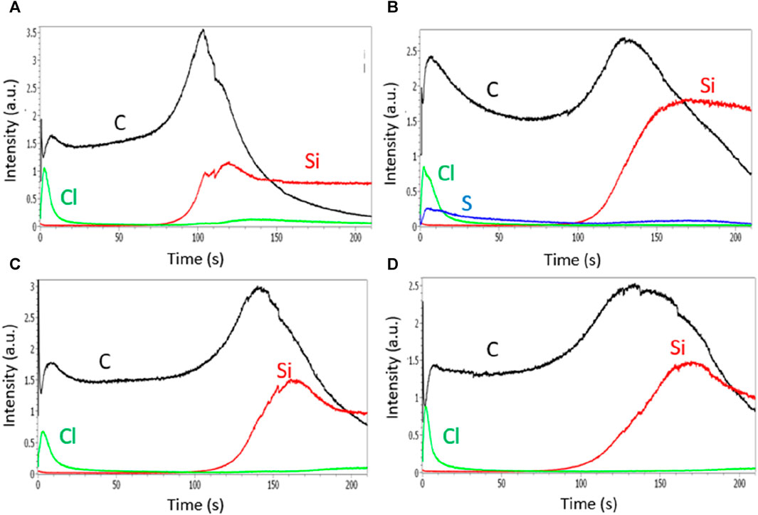
FIGURE 6. GDOES depth profiles of polyaniline films grown in HCl solutions containing no surfactant (A), SDS (B), Tritonx100 (C), or CTAB (D) at 0.01 M.
A high signal of Cl element is observed at the surface of the PANI/HCl film during the first seconds of analysis, indicating an inhomogeneous distribution of the Cl− anions in the PANI film with a higher concentration of Cl− at the top surface than inside the PANI matrix (Figures 6A-D). Similar GDOES profiles are obtained for PANI films containing surfactants indicating that chloride ions are not present in the bulk of these films, but only at the top part of the films which is certainly favorable to the doping/dedoping of the PANI films during its oxidation/reduction. In addition, Figure 6B shows that the sulfur atoms from the SDS surfactant also remain on the top surface of the film, therefore the sponginess does not seem sufficient for the anions to penetrate the film.
The GDOES profiles of PANI films prepared in CSA solutions are very different. Indeed, the distribution of camphorsulfonate anions seems much more homogeneous since the signal of the sulfur element, allowing to track the presence of the CSA anions, is present on the whole area corresponding to the erosion of carbon and thus to the presence of the polymer (Figure 7). It is therefore likely that camphorsulfonate ions are trapped in the film during electropolymerization and cannot emerge from the film due to their high size and low mobility while chloride ions, smaller and more mobile, are able to get out of the film to go to the top surface of the film using its sponginess. This less spongy structure prevents counter-anions from getting deeply inside the PANI films and being trapped, and so facilitates the doping/dedoping of the PANI film.
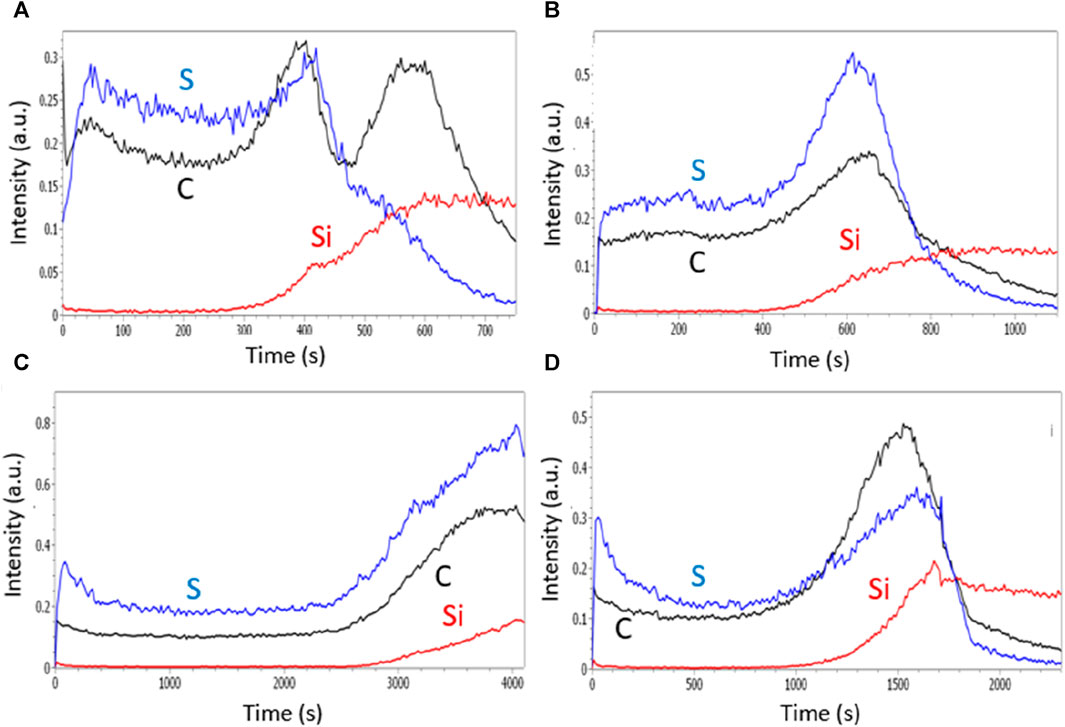
FIGURE 7. GDOES depth profiles of polyaniline films grown in CSA solutions containing no surfactant (A), SDS (B), Tritonx100 (C), or CTAB (D) at 0.01 M.
3.4 Study of the electroactivity and conductivity of the electrodeposited polyaniline films
3.4.1 Electrochemical activity measurements
The electrochemical activity of the electrodeposited PANI films is then assessed since the measurement of the electroactivity indicates if the films pass easily or not from a doped to a dedoped form, through the exchange of anions between the film and the electrolyte. For this purpose, the electrode with the attached polymer film is removed from the electrolyte growth solution and placed in a monomer-free aqueous acid solution for post-polymerization voltammetric analysis. The post-polymerization CVs of the PANI films grown in HCl solutions show several oxidation and reduction peaks indicating that doping/dedoping of each PANI film by the anions is readily accomplished (the first cycle is given in Figure 8A and the following scans in the Supplementary Files 5, 6). Moreover, the intensity of the peaks remains constant during the 5 cycles which means that the electroactivity does not decrease by cycling. The intensity of these peaks is high indicating that ionic exchanges between the PANI film and the electrolyte occurs easily with chloride counter-anions. This result can be explained by: (i) the small size and high mobility of the chloride ions, (ii) the presence of the chloride ions at the top of the film and not inside the film, as shown by the GDOES experiments. It is also noticeable that the highest electroactivity is obtained for the PANI/HCl films grown in surfactant-free solutions. So, the presence of a surfactant in the electrolytic solution seems to be less favorable to the doping/dedoping process of the PANI films.
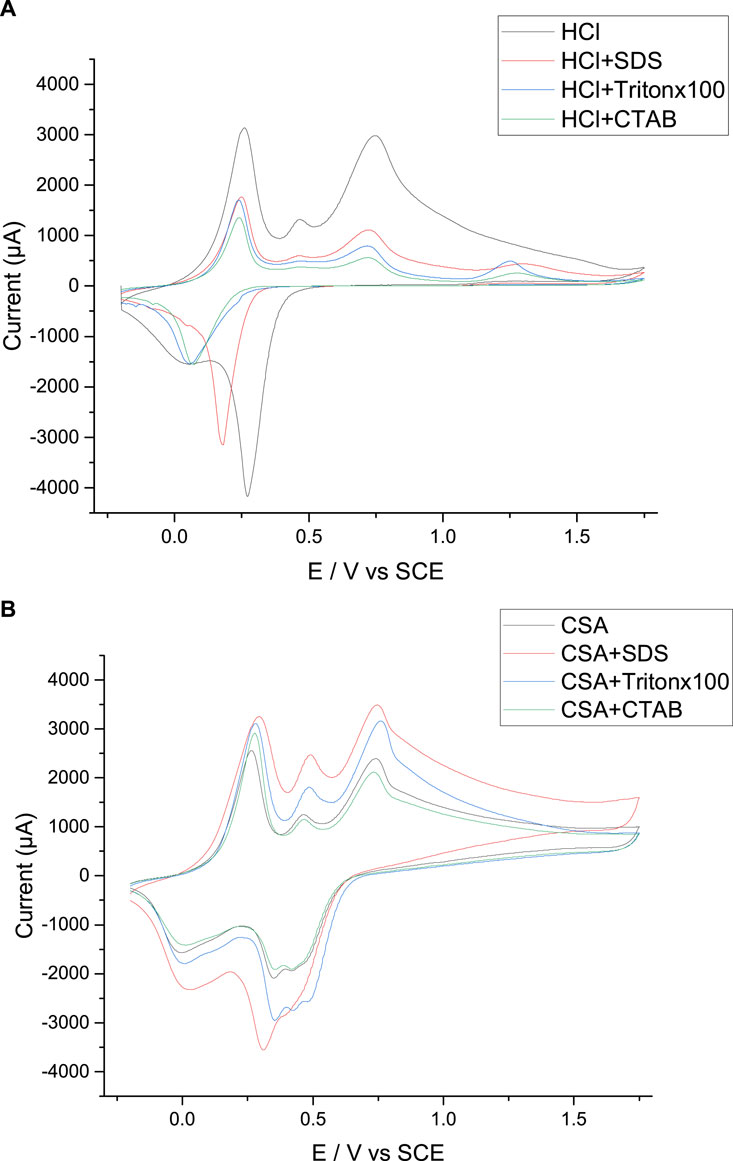
FIGURE 8. Post-polymerization cyclic voltammetry of the PANI films prepared in HCl (A) and CSA (B) solutions. Scan speed: 50 mV s−1. WE: Pt.
The post-polymerization CVs are then performed in the CSA solutions with and without surfactant and compared with those obtained with PANI grown in HCl solutions. Thus, it is visible that the intensity of the peaks is higher for the PANI/HCl film than for the PANI/CSA film in the absence of surfactant which indicates that ionic exchanges between the PANI film and the electrolyte occurs more easily with chlorides counter-ions than with camphorsulfonate ions (the first cycle is given in Figure 8B and the following scans in the Supplementary Files 7, 8). This result can be explained by the fact that the chloride anions are present only on the surface while the CSA anions are incorporated into the polymer film, as previously demonstrated by the GDOES experiments. On the contrary, the electrochemical activity of the PANI films obtained in the presence of SDS, Tritonx100 and CTAB (Figure 8B) presents interest since the peak currents are higher than those obtained in HCl solutions (Figure 8A).
3.4.2 Galvanostatic charge-discharge curves
Galvanostatic charge and discharge (GCD) curves were made for different current intensities. Figure 9 shows the galvanostatic charge-discharge of PANI/HCl + Tritonx100 (Figure 9A) and PANI/CSA + Tritonx100 (Figure 9B) for different applied current densities (from 1.0 to 1.5 mA/cm2). GCD curves were not symmetrical between the charge-discharge processes, indicating that polyaniline films are pseudo-capacitive materials. Indeed, the initiation of the discharge curve showed a resistive behavior, characteristic of PANI-modified electrodes. Also, a variable potential drop with time could be observed, indicating that there were consecutive electron exchanges on the modified electrode through faradic reactions (Ghenaatian et al., 2012; Eftekhari et al., 2017b; Martins et al., 2020). Only the curves obtained with PANI/HCl + Tritonx100 and PANI/CSA + Tritonx100 are shown here, but the GCD curves all had the same appearance, whatever the electrolyte composition (Supplementary Files 9, 10).
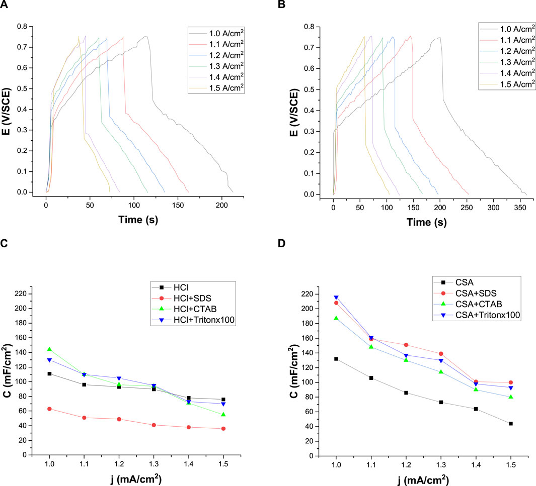
FIGURE 9. Galvanostatic charge-discharge of a polyaniline/FTO electrode between 0 and +0.75 V/SCE in a HCl + Tritonx100 (A) and in a CSA + Tritonx100 (B) solution for different applied current densities. Variation of capacitance as a function of current densities for a PANI/FTO electrode obtained from HCl solutions with or without surfactant (C) and from CSA solutions with or without surfactant (D). WE: Pt.
Moreover, the increase in the applied current density led to the increase in the voltage drop, thus reducing charge and discharge times and the specific capacitance, which can be calculated from the galvanostatic charge-discharge using the following equation (Eq. 2):
Where j is the applied current density, Δt is the discharge time and ΔE is the potential window.
The calculated specific capacitances for the different applied densities are represented in Figure 9C for PANI grown in HCl solutions and in Figure 9D for PANI films grown in CSA solutions. The capacitance of the electrode is not constant and depends strongly on the current density. Indeed, the capacitance of the PANI-modified electrodes decreases as the imposed current increases whatever the composition of the electrolytic solution, as previously observed by Aynaou et al. (2022). This decrease in capacitance is explained by the low diffusion of ions in the electrolyte (Mondal et al., 2007). The capacitances obtained for PANI films grown in HCl are lower than those obtained for PANI films grown in CSA. Indeed, PANI films grown in CSA and surfactants reached capacitance values higher than 200 mA/cm2, these values being strongly higher than those previously published (Aynaou et al., 2022). In PANI/HCl films, chloride anions penetrated the film, whereas in PANI/CSA films, camphorsulfonate anions remained on the film surface and in the bulk, acting as a charge reservoir, and leading to higher specific capacities. However, it must be noticed that the decrease in capacitance with applied current density was much less marked for polyaniline films prepared in HCl than for films prepared in CSA, indicating that PANI-HCl films had a more constant capacitance. This means that PANI-HCl films can more easily maintained their capacitance under increased current, which is of importance for the electrode materials of electrochemical capacitors.
3.4.3 Electrochemical impedance spectroscopy measurements
The most common way of analyzing EIS data is to assimilate electrochemical phenomena (interfacial charging, electron transfer, and mass transport) to electrical elements and arrange them in an equivalent circuit corresponding to the electrochemical cell used. In this work, the EIS experimental data are fitted with the EC-Lab software considering a χ2 < 10−3 as a satisfactory goodness of fit. For the polyaniline films previously electrodeposited, such low value of goodness of fit (Table 1) is obtained using the simple Randles circuit which is probably the most frequently used equivalent circuit to characterize the behavior of polymer electrodeposited films such as polyaniline films (Xing et al., 2014; Aggas et al., 2018) (Figure 10A). In this model, the circuit is composed of a solution resistance (Rs) in series with a parallel combination of a constant phase element (Q), which models the behavior of a double layer that is an imperfect capacitor, and a charge transfer resistance (Rct) both used to characterize Faradaic processes. In the Nyquist plot, the imaginary part of the impedance is represented as a function of the real part of the impedance, each point in the Nyquist plot corresponding to impedance at one frequency. For the different polyaniline films electrodeposited in this work, the Nyquist plot contains a semi-circular arc intersecting the real axis at two places: the intercept closest to the origin gives the value of solution resistance (Rs) and corresponds to the highest frequencies while the intercept farthest from the origin gives the value of total resistance (Rs + Rct) and corresponds to the lowest frequencies used. Table 1 gathers the values extracted from the application of a simple Randles equivalent circuit model to the impedance data from the various PANI films grown in HCl and CSA solutions. First of all, it can be noticed that all the solutions have similar resistances (146–207 Ω), which is consistent with the fact that they all contain [Fe(CN)6]3− and [Fe(CN)6]4− (5 mM) dissolved in a PBS solution.
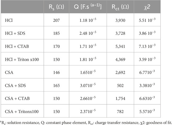
TABLE 1. Values extracted from the application of a simple Randles equivalent circuit model to the impedance data for the different PANI films.
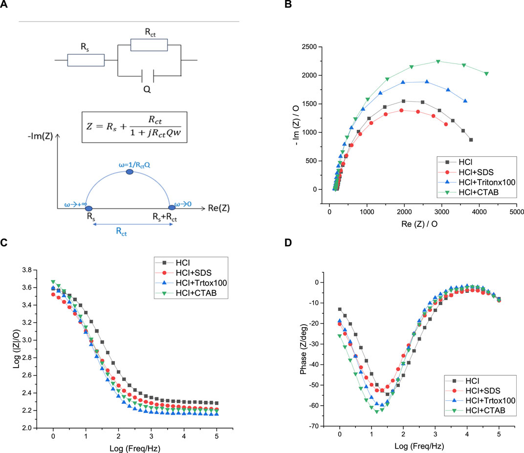
FIGURE 10. Equivalent circuit (A), Nyquist plots (B), Bode-impedance plots (C), and Bode-phase plots (D) of polyaniline films grown in HCl solutions containing no surfactant (black), SDS (red), Tritonx100 (blue), or CTAB (green) in 5 mM [Fe(CN)6]3−/4−, initial potential E = +0.5 V/SCE. Highest Freq = 100 kHz, Lowest Freq = 1 Hz. WE: Pt.
Considering PANI/HCl films, PANI/HCl + CTAB presents the highest Rct value of 5,341 Ω which evidences the lowest conductivity of this film since a high Rct value implies high electron transfer resistance to the redox-probe and the blockage of charge transfer. The resistance of the other polyaniline films is lower and the calculated Rct values are relatively close since they vary from 3,728 Ω for PANI/HCl + SDS to 4,369 Ω for PANI/HCl + Tritonx100. However, a major limitation in the Nyquist plot is that the frequency can not be easily deduced from the plot. So, it is useful to draw the Bode plot, where the impedance is plotted with the absolute value of impedance, or the phase angle is plotted on the y-axis and the logarithmic frequency plotted on the x-axis. In our case, the results of the Nyquist plot are confirmed by the Bode plots. Indeed, Figure 10B shows that there is no significant difference between the impedance of each of the PANI films grown in HCl solutions while the phase diagram of Figure 10C confirms that the most resistive films are PANI/HCl + CTAB and PANI/HCl + Tritonx100 since their phase change is greater than the ones of PANI/HCl and PANI/HCl + SDS. In the end, it appears that all the polyaniline films grown in HCl solutions have a relatively similar conductivity since their conductivity differs in a narrow range of resistance of 3,728–5341Ω.
As shown in Figure 11A, the Nyquist plots of the polyaniline films grown in CSA indicate that PANI/CSA + SDS film, which are the most electroactive, presents the lowest Rct value of 502 Ω which evidences the highest conductivity of this film (Table 1). The Rct value of the PANI/CSA + Tritonx100 is also lower (782 Ω) than the one of PANI/CSA + CTAB (1,754 Ω). The most resistive PANI/CSA film is grown in the absence of surfactant (2,692 Ω). It therefore seems beneficial to add a surfactant to the electrolyte solution to increase the conductivity of the polyaniline film grown in CSA solutions. This is further confirmed by observing the Bode plots. Indeed, in the Bode impedance plot, the impedance is the lowest for PANI/CSA + SDS and the highest for PANI/CSA at frequencies lower than log 1.5 = 30 Hz (Figure 11B). In addition, the Bode phase angle plot shows that the maximum phase angle at a frequency of 30 Hz varies from −20° for PANI/CSA + SDS to −60° for PANI/CSA, confirming an increase of resistance in the absence of surfactant (Figure 11C). It is also noteworthy that the conductivity of the PANI/CSA films is much higher than those of the PANI/HCl films since the conductivity of the PANI/CSA films varied from 502 to 2,692 Ω while the conductivity of the PANI/HCl films varied from 3,939 to 5,341 Ω. The fact that the conductivity of PANI films changes as a function of the dopant is consistent with previous studies that have shown the strong impact of the nature of the counter-anion on the conductivity of electrodeposited polyaniline and polypyrrole films (Hao et al., 2010; Patois et al., 2010). It can also be supposed that the presence of the CSA dopant in the whole film and not only on surface of the film partly explains the higher conductivity of PANI/CSA films. Also, the conductivity variations due to changes in electrolyte composition are far much greater in CSA solutions than in HCl solutions. As the acid and surfactant act as a dopant, it is not surprising that conductivity varies according to the nature of the acid and surfactant. Indeed, the surfactants used do not have the same charge, which causes differences in conductivity, and the acids and surfactants do not have the same size, which leads to differences in morphology affecting conductivity. Similarly, a previous study has shown that the nature of the dopant strongly influences the conductivity value of polypyrrole films (Patois et al., 2010).
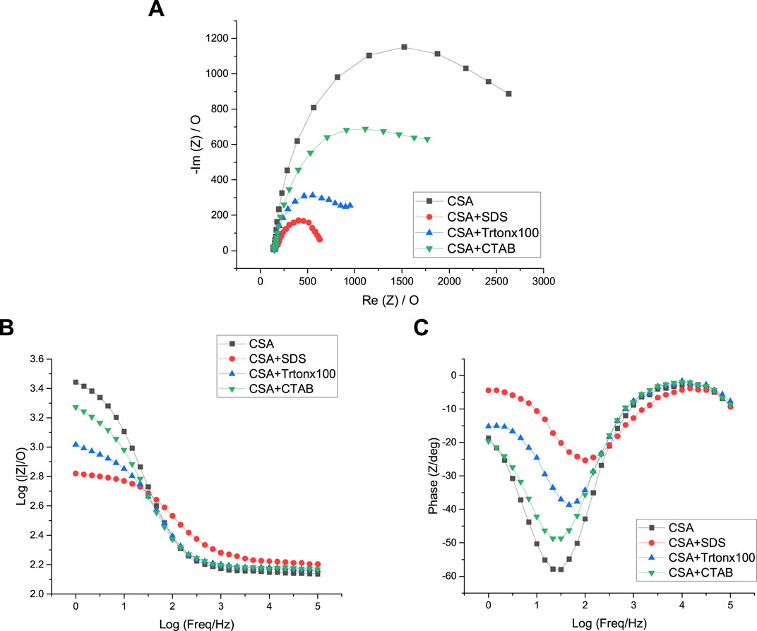
FIGURE 11. Nyquist plots (A), Bode-impedance plots (B), and Bode-phase plots (C) of polyaniline films grown in CSA solutions containing no surfactant (black), SDS (red), Tritonx100 (blue), or CTAB (green) in 5 mM [Fe(CN)6]3−/4−, initial potential E = +0.5 V/SCE. Highest Freq = 100 kHz, Lowest Freq = 1 Hz. WE: Pt.
4 Conclusion
The electrochemical oxidation of aniline in the presence of a positive, negative, or neutral surfactant in HCl or CSA solutions has successfully led to the formation of green solid polymer films, although the properties of these resulting films appeared to depend on the surfactant and the dopant used.
Electropolymerizations performed in HCl solutions led to spongy morphologies, except in the presence of Tritonx100. Chloride counter-anions were present only on the top surface of these films as demonstrated by GDOES experiments which impacts the electroactivity of the films. This electroactivity is the highest in the absence of surfactants mainly due to steric hindrance. The thickness of the films also varies according to the surfactant, the thickness of the PANI/HCl + SDS films being the lowest due to repulsive interactions between the negative charges of the chlorides and sulfonates anions. Also, the conductivity of the PANI/HCl films differs in a narrow range of resistance of 3,728–5341Ω.
Electropolymerizations performed in CSA solutions have led to more compact and fibrous morphologies than in HCl solutions, except in the presence of SDS. This is consistent with the fact that sulfonate counter-anions were present throughout the film and not only on the surface of these films as demonstrated by GDOES. Furthermore, the difference in morphology can explain that the electroactivity of films in the presence of surfactants was higher for the PANI films grown in CSA solutions than those grown in HCl solutions. Also, the thickness of the PANI/CSA + SDS films was the highest one, probably due to the presence of sulphonate groups both in the acid and in the surfactant. The conductivity of PANI films grown in CSA solutions was much higher than that of PANI films grown in HCl solutions. The most conductive films were those obtained in the presence of CSA and SDS, and in the presence of CSA and Tritonx100, both of which also exhibited the best electroactivities, thus favoring doping. Besides, the specific capacitance of the PANI/CSA films was higher and more sensitive to current density variation than the one of films doped with HCl.
More generally, the results obtained in this work demonstrate that the addition of a well-chosen surfactant allows to tune the conductivity and the capacitance of polyaniline films, which is of interest for applications such as gas detection using resistive sensors to optimize the initial conductivity of the polymer film used as sensitive layer, or for the fabrication of conducting polymer-based supercapacitors and energy storage devices. The prevention of corrosion could also be a potential application for such polyaniline films since sulfonated polyaniline films have already been used for such application [68].
Data availability statement
The original contributions presented in the study are included in the article/Supplementary Material, further inquiries can be directed to the corresponding author.
Author contributions
AK: Data curation, Formal Analysis, Writing–original draft. CM: Conceptualization, Data curation, Supervision, Writing–original draft. I-AP: Investigation, Resources, Writing–review and editing. HH: Investigation, Resources, Writing–review and editing. VM: Investigation, Resources, Writing–review and editing. BL: Investigation, Writing–review and editing. NR: Funding acquisition, Writing–review and editing. CD: Funding acquisition, Investigation, Supervision, Validation, Writing–review and editing. SL: Conceptualization, Formal Analysis, Funding acquisition, Investigation, Project administration, Supervision, Writing–original draft, Writing–review and editing.
Funding
The author(s) declare that financial support was received for the research, authorship, and/or publication of this article. AK was funded, through a PhD grant, by the Bourgogne Franche-Comté Regional Council and by the IMT Nord Europe. This work was supported by the instruments and staff of the Plateforme Chimie UTINAM (PCU). This work was also partly supported by the French RENATECH network and its FEMTO-ST technological facility.
Conflict of interest
The authors declare that the research was conducted in the absence of any commercial or financial relationships that could be construed as a potential conflict of interest.
Publisher’s note
All claims expressed in this article are solely those of the authors and do not necessarily represent those of their affiliated organizations, or those of the publisher, the editors and the reviewers. Any product that may be evaluated in this article, or claim that may be made by its manufacturer, is not guaranteed or endorsed by the publisher.
Supplementary material
The Supplementary Material for this article can be found online at: https://www.frontiersin.org/articles/10.3389/fmats.2024.1358534/full#supplementary-material
References
Abd-El-Nabey, B. A., Abdullatef, O. A., El-Naggar, G. A., Matter, E. A., and Salman, R. M. (2016). Effect of tween 80 surfactant on the electropolymerization and corrosion performance of polyaniline on mild steel. Int. J. Electrochem. Sci. 11, 2721–2733. doi:10.20964/110402721
Abd-Elwahed, A., and Holze, R. (2002). Ion size and size memory effects with electropolymerized polyaniline. Synth. Mater. 131, 61–70. doi:10.1016/S0379-6779(02)00153-4
Aggas, J. R., Harrell, W., Lutkenhaus, J., and Guiseppi-Elie, A. (2018). Metal–polymer interface influences apparent electrical properties of nano-structured polyaniline films. Nanoscale 10, 672–682. doi:10.1039/C7NR06503E
Ashokan, S., Ponnuswamy, V., Jayamurugan, P., Chandrasekaran, J., and Rao, Y. S. (2015). Influence of the counter ion on the properties of organic and inorganic acid doped polyaniline and their Schottky diodes. Superlat. Microstruct. 85, 282–293. doi:10.1016/j.spmi.2015.04.005
Awata, R., Shehab, M., El Tahan, A., Soliman, M., and Ebrahim, S. (2020). High performance supercapacitor based on camphor sulfonic acid doped polyaniline/multiwall carbon nanotubes nanocomposite. Electrochim. Acta 347, 136229. doi:10.1016/j.electacta.2020.136229
Aynaou, A., Youbi, B., Ait Himi, M., Lghazi, Y., Bahar, J., El Haimer, C., et al. (2022). Electropolymerization investigation of polyaniline films on ITO substrate. Mat. Today Proc. 66, 335–340. doi:10.1016/j.matpr.2022.05.437
Baba, A., Tian, S., Stefani, F., Xia, C., Wang, Z., Advincula, R. C., et al. (2004). Electropolymerization and doping/dedoping properties of polyaniline thin films as studied by electrochemical-surface plasmon spectroscopy and by the quartz crystal microbalance. J. Electroanal. Chem. 562, 95–103. doi:10.1016/j.jelechem.2003.08.012
Bazli, L., Yusuf, M., Farahani, A., Kiamarzi, M., Seyedhosseini, Z., Nezhadmansari, M., et al. (2020). Application of composite conducting polymers for improving the corrosion behavior of various substrates: a Review. J. Compos. Comp. 2, 228–240. doi:10.29252/jcc.2.4.7
Bhandari, H., Choudhary, V., and Dhawan, S. K. (2011). Influence of self-doped poly(aniline-co-4-amino-3-hydroxy-naphthalene-1-sulfonic acid) on corrosion inhibition behaviour of iron in acidic medium. Synth. Mater. 161, 753–762. doi:10.1016/j.synthmet.2011.01.026
Bhandari, H., Srivastav, R., Choudhary, V., and Dhawan, S. K. (2010). Enhancement of corrosion protection efficiency of iron by poly(aniline-co-amino-naphthol-sulphonic acid) nanowires coating in highly acidic medium. Thin Solid Films 519, 1031–1039. doi:10.1016/j.tsf.2010.08.038
Celiesiute, R., Ramanaviciene, A., Gicevicius, M., and Ramanavicius, A. (2019). Electrochromic sensors based on conducting polymers, metal oxides, and coordination complexes. Crit. Rev. Anal. Chem. 49, 195–208. doi:10.1080/10408347.2018.1499009
Chandrakanthi, N., and Careem, M. (2000). Thermal stability of polyaniline. Polym. Bull. 44, 101–108. doi:10.1007/s002890050579
Cho, S., Lee, J. S., and Joo, H. (2019). Recent developments of the solution-processable and highly conductive polyaniline composites for optical and electrochemical applications. Polymers 11, 1965. doi:10.3390/polym11121965
Deshpande, P. P., Jadhav, N. G., Gelling, V. J., and Sazou, D. (2014). Conducting polymers for corrosion protection: a review. J. Coat. Technol. Res. 11, 473–494. doi:10.1007/s11998-014-9586-7
Eftekhari, A., Li, L., and Yang, Y. (2017a). Polyaniline supercapacitors. J. Power Sources 347, 86–107. doi:10.1016/j.jpowsour.2017.02.054
Eftekhari, A., Li, L., and Yang, Y. (2017b). Polyaniline supercapacitors. J. Power Sources 347, 86–107. doi:10.1016/j.jpowsour.2017.02.054
Gao, F., Mu, J., Bi, Z., Wang, S., and Li, Z. (2021). Recent advances of polyaniline composites in anticorrosive coatings: a review. Progr. Org. Coat. 151, 106071. doi:10.1016/j.porgcoat.2020.106071
Garai, A., Chatterjee, S., and Nandi, A. K. (2010). Nanocomposites of silver nanoparticle and dinonylnaphthalene disulfonic acid-doped thermoreversible polyaniline gel. Polym. Eng. Sci. 50, 446–454. doi:10.1002/pen.21545
Ghenaatian, H. R., Mousavi, M. F., and Rahmanifar, M. S. (2012). High performance hybrid supercapacitor based on two nanostructured conducting polymers: self-doped polyaniline and polypyrrole nanofibers. Electrochim. Acta 78, 212–222. doi:10.1016/j.electacta.2012.05.139
Giz, M. J., de Albuquerque Maranhao, S. L., and Torresi, R. M. (2000). AFM morphological study of electropolymerised polyaniline films modified by surfactant and large anions. Electrochem. Comm. 2, 377–381. doi:10.1016/S1388-2481(00)00041-2
Hao, Q., Lei, W., Xia, X., Yan, Z., Yang, X., Lu, L., et al. (2010). Exchange of counter anions in electropolymerized polyaniline films. Electrochim. Acta 55, 632–640. doi:10.1016/j.electacta.2009.09.018
Holze, R. (2000). “Spectroelectrochemistry of conducting polymers,” in Handbook of electronic and photonic materials and devices. Editor H. S. Nalwa (San Diego: Academic Press), 209.
Inamdar, A. I., Kim, Y. S., Sohn, J. S., Im, H., Kim, H., Kim, D. Y., et al. (2011). Supercapacitive characteristics of electrodeposited polyaniline thin films grown on indium-doped tin-oxide substrates. J. Kor. Phys. Soc. 59, 145–149. doi:10.3938/jkps.59.145
Jamdegni, M., and Kaur, A. (2020). Role of polarity of surfactants on the morphology of electrochemically synthesized polyaniline nanostructures: towards faster and efficient electrochromic response. Thin Solid Films 714, 138373. doi:10.1016/j.tsf.2020.138373
Jaymand, M. (2013). Recent progress in chemical modification of polyaniline. Progr. Polym. Sci. 38, 1287–1306. doi:10.1016/j.progpolymsci.2013.05.015
Ji, X., Leng, M., Xie, H., Wang, C., Dunbar, K. R., Zou, Y., et al. (2020). Extraordinary electrochemical stability and extended polaron delocalization of ladder-type polyaniline-analogous polymers. Chem. Sci. 11, 12737–12745. doi:10.1039/D0SC03348K
Kanungo, M., Kumar, A., and Contractor, A. Q. (2002). Studies on electropolymerization of aniline in the presence of sodium dodecyl sulfate and its application in sensing urea. J. Electroanal. Chem. 528, 46–56. doi:10.1016/S0022-0728(02)00770-2
Khan, R., Solanki, P. R., Kaushik, A., Singh, S. P., Ahmad, S., and Malhotra, B. D. (2009). Cholesterol biosensor based on electrochemically prepared polyaniline conducting polymer film in presence of a nonionic surfactant. J. Polym. Res. 16, 363–373. doi:10.1007/s10965-008-9237-8
Kovac, J., Ekar, J., Cekada, M., Zajickova, L., Necas, D., Blahova, L., et al. (2022). Depth profiling of thin plasma-polymerized amine films using GDOES in an Ar-O2 plasma. Appl. Surf. Sci. 581, 152292. doi:10.1016/j.apsusc.2021.152292
Krukiewicz, K., and Katunin, A. (2016). The effect of reaction medium on the conductivity and morphology of polyaniline doped with camphorsulfonic acid. Synth. Mater. 214, 45–49. doi:10.1016/j.synthmet.2016.01.017
Kumar, V., Mirzaei, A., Bonyani, M., Kim, K. H., Kim, H. W., and Kim, S. S. (2020). Advances in electrospun nanofiber fabrication for polyaniline (PANI)-based chemoresistive sensors for gaseous ammonia. TrAC 129, 115938. doi:10.1016/j.trac.2020.115938
Lee, K. H., Park, B. J., Song, D. H., Chin, I. J., and Choi, H. J. The role of acidic m-cresol in polyaniline doped by camphorsulfonic acid. Polymer 2009, 50, 4372–4377. doi:10.1016/j.polymer.2009.07.009
Lee, S., Kim, W. J., and Chung, M. (2021). Enhanced electrochemical biosensing on gold electrodes with a ferri/ferrocyanide redox couple. Analyst 146, 5236–5244. doi:10.1039/D1AN00952D
Liao, G., Li, Q., and Xu, Z. (2019). The chemical modification of polyaniline with enhanced properties: a review. Progr. Org. Coat. 126, 35–43. doi:10.1016/j.porgcoat.2018.10.018
Liu, P., Yan, J., Guang, Z., Huang, Y., Li, X., and Huang, W. (2019). Recent advancements of polyaniline-based nanocomposites for supercapacitors. J. Power Sources 424, 108–130. doi:10.1016/j.jpowsour.2019.03.094
Liu, Y., Cao, S., Liang, Y., Han, X., Yang, T., Zeng, R., et al. (2022). Robust and swiftly multicolor Zn2+-electrochromic devices based on polyaniline cathode. Sol. Ener. Mat. Sol. Cells 238, 111616. doi:10.1016/j.solmat.2022.111616
Ma, Y., Zhang, C., Hou, C., Zhang, H., Zhang, H., Zhang, Q., et al. (2017). Cetyl trimethyl ammonium bromide (CTAB) micellar templates directed synthesis of water-dispersible polyaniline rhombic plates with excellent processability and flow-induced color variation. Polymer 117, 30–36. doi:10.1016/j.polymer.2017.04.010
Maity, N., Dawn, A., Kuila, A., and Nandi, A. K. (2018). Supramolecular grafting of doped polyaniline leads to an unprecedented solubility enhancement, radical cation stabilization, and morphology transformation. J. Mat. Chem. A 6, 12654–12662. doi:10.1039/C8TA04092C
Manne, S., and Gaub, H. E. (1995). Molecular organization of surfactants at solid-liquid interfaces. Science 270, 1480–1482. doi:10.1126/science.270.5241.1480
Martins, J. C., Neto, J. C. D. M., Passos, R. R., and Pocrifka, L. A. (2020). Electrochemical behavior of polyaniline: a study by electrochemical impedance spectroscopy (EIS) in low-frequency. Solid State Ionics 346, 115198. doi:10.1016/j.ssi.2019.115198
Mondal, S. K., Barai, K., and Munichandraiah, N. (2007). High capacitance properties of polyaniline by electrochemical deposition on a porous carbon substrate. Electrochim. Acta 52, 3258–3264. doi:10.1016/j.electacta.2006.09.067
Motheo, A. J., Santos, J. R., Venancio, E. C., and Mattoso, L. H. C. (1998). Influence of different types of acidic dopant on the electrodeposition and properties of polyaniline films. Polymer 39, 6977–6982. doi:10.1016/S0032-3861(98)00086-X
Mu, S. L., and Kan, J. (1996). Evidence for the autocatalytic polymerization of aniline. Electrochim. Acta 41, 1593–1599. doi:10.1016/0013-4686(95)00410-6
Olinga, T. E., Fraysse, J., Travers, J. P., Dufresne, A., and Pron, A. (2000). Highly conducting and solution-processable polyaniline obtained via protonation with a new sulfonic acid containing plasticizing functional groups. Macromolecules 33, 2107–2113. doi:10.1021/ma991525i
Patois, T., Lakard, B., Martin, N., and Fievet, P. (2010). Effect of various parameters on the conductivity of free standing electrosynthesized polypyrrole films. Synth. Mater. 160, 2180–2185. doi:10.1016/j.synthmet.2010.08.005
Patois, T., Lakard, B., Monney, S., Roizard, X., and Fievet, P. (2011). Characterization of the surface properties of polypyrrole films: influence of electrodeposition parameters. Synth. Mater. 161, 2498–2505. doi:10.1016/j.synthmet.2011.10.003
Pina, C. D., and Falletta, E. (2022). Advances in polyaniline for biomedical applications. Curr. Med. Chem. 29, 329–357. doi:10.2174/0929867328666210419135519
Qiu, Y., Lu, S., Wang, S., Zhang, X., He, S., and He, T. (2014). High-performance polyaniline counter electrode electropolymerized in presence of sodium dodecyl sulfate for dye-sensitized solar cells. J. Power Sources 253, 300–304. doi:10.1016/j.jpowsour.2013.12.061
Raj, J. A., Mathiyarasu, J., Vedhi, C., and Manisankar, P. (2010). Electrochemical synthesis of nanosize polyaniline from aqueous surfactant solutions. Mat. Lett. 64, 895–897. doi:10.1016/j.matlet.2010.01.019
Routh, P., Garai, A., and Nandi, A. K. (2011). Optical and electronic properties of polyaniline sulfonic acid–ribonucleic acid–gold nanobiocomposites. PCCP 13, 13670–13682. doi:10.1039/C1CP20365G
Samadi, A., Xie, M., Li, J., Shon, H., Zheng, C., and Zhao, S. (2021). Polyaniline-based adsorbents for aqueous pollutants removal: a review. Chem. Eng. J. 418, 129425. doi:10.1016/j.cej.2021.129425
Sanchez-Amaya, M., Bárcena-Soto, M., Antaño-López, R., Rodríguez-López, A., Barragan, J. A., Gutierrez-Becerra, A., et al. (2022). Effect of wide ranges of polarization and concentration on the behavior of ferricyanide/ferrocyanide systems studied through electrochemical measurements. Int. J. Electrochem. Sci. 17, 22016. doi:10.20964/2022.01.11
Sizun, T., Patois, T., Bouvet, M., and Lakard, B. (2012). Microstructured electrodeposited polypyrrole–phthalocyanine hybrid material, from morphology to ammonia sensing. J. Mat. Chem. 22, 25246–25253. doi:10.1039/C2JM35356C
Giz, M. J., de Albuquerque Maranhao, S. L., and Torresi, R. M. (2000 ). AFM morphological study of electropolymerised polyaniline films modified by surfactant and large anions. Electrochem. Comm. 2, 377–381. doi:10.1016/S1388-2481(00)00041-2
Wang, Y., and Levon, K. (2012). Influence of dopant on electroactivity of polyaniline. Macromol. Symp. 317, 240–247. doi:10.1002/masy.201200008
Wu, D. C., Xu, F., Sun, B., Fu, R. W., He, H. K., and Matyjaszewski, K. (2012). Design and preparation of porous polymers. Chem. Rev. 112, 3959–4015. doi:10.1021/cr200440z
Wu, J., Sun, Y., Xu, W., and Zhang, Q. (2014). Investigating thermoelectric properties of doped polyaniline nanowires. Synth. Mater. 189, 177–182. doi:10.1016/j.synthmet.2014.01.007
Wu, L., Han, Y., Zheng, H., Cao, S., Huang, W., Chen, N., et al. (2018). EQCM studies of polyaniline film in a H2SO4 solution in ethylene glycol. J. Electrochem. Soc. 165, H711–H716. doi:10.1149/2.0831811jes
Wu, Y., Wang, J., Ou, B., Zhao, S., and Wang, Z. (2019). Some important issues of the commercial production of 1-D nano-PANI. Polymers 11, 681. doi:10.3390/polym11040681
Xiao, Y., Lin, J. Y., Wang, W. Y., Tai, S. Y., Yue, G., and Wu, J. (2013). Enhanced performance of low-cost dye-sensitized solar cells with pulse-electropolymerized polyaniline counter electrodes. Electrochim. Acta 90, 468–474. doi:10.1016/j.electacta.2012.12.055
Xie, J., Zong, C., Han, X., Ji, H., Wang, J., Yang, X., et al. (2016). Redox-switchable surface wrinkling on polyaniline film. Macromol. Rap. Comm. 37, 637–642. doi:10.1002/marc.201500700
Xing, C., Zhang, Z., Yu, L., Zhang, L., and Bowmaker, G. A. (2014). Electrochemical corrosion behavior of carbon steel coated by polyaniline copolymers micro/nanostructures. RSC Adv. 4, 32718–32725. doi:10.1039/C4RA05826G
Xing, J., Liao, M., Zhang, C., Yin, M., Li, D., and Song, Y. (2017). The effect of anions on the electrochemical properties of polyaniline for supercapacitors. PCCP 19, 14030–14041. doi:10.1039/C7CP02016C
Zare, E. N., Makvandi, P., Ashtari, B., Rossi, F., Motahari, A., and Perale, G. (2019). Progress in conductive polyaniline-based nanocomposites for biomedical applications: a review. J. Med. Chem. 63, 1–22. doi:10.1021/acs.jmedchem.9b00803
Zare, E. N., Motahari, A., and Sillanpää, M. (2018). Nanoadsorbents based on conducting polymer nanocomposites with main focus on polyaniline and its derivatives for removal of heavy metal ions/dyes: a review. Env. Res. 162, 173–195. doi:10.1016/j.envres.2017.12.025
Zhang, W., Cao, S., Wu, Z., Zhang, M., Cao, Y., Guo, J., et al. (2019). High-performance gas sensor of polyaniline/carbon nanotube composites promoted by interface engineering. Sensors 20, 149. doi:10.3390/s20010149
Keywords: electrodeposition, conducting polymers, polyaniline, surfactant, thin films
Citation: Kayishaer A, Magnenet C, Pavel I-A, Halima HB, Moutarlier V, Lakard B, Redon N, Duc C and Lakard S (2024) Influence of surfactant on conductivity, capacitance and doping of electrodeposited polyaniline films. Front. Mater. 11:1358534. doi: 10.3389/fmats.2024.1358534
Received: 19 December 2023; Accepted: 19 February 2024;
Published: 28 February 2024.
Edited by:
Ilaria Cacciotti, University Niccolò Cusano, ItalyCopyright © 2024 Kayishaer, Magnenet, Pavel, Halima, Moutarlier, Lakard, Redon, Duc and Lakard. This is an open-access article distributed under the terms of the Creative Commons Attribution License (CC BY). The use, distribution or reproduction in other forums is permitted, provided the original author(s) and the copyright owner(s) are credited and that the original publication in this journal is cited, in accordance with accepted academic practice. No use, distribution or reproduction is permitted which does not comply with these terms.
*Correspondence: Sophie Lakard, c29waGllLmxha2FyZEB1bml2LWZjb210ZS5mcg==