 J. N. M. Boots
 R. Kooi
 T. E. Kodger
 J. van der Gucht
- 1Physical Chemistry and Soft Matter, Wageningen University and Research, Wageningen, Netherlands
- 2Department of Mechanical Engineering, Eindhoven University of Technology, Eindhoven, Netherlands
Most materials are mechanically heterogeneous on a certain length scale. In many applications, this heterogeneity is crucial for the material’s function, and exploiting mechanical heterogeneity could lead to new materials with interesting features, which require accurate understanding of the local mechanical properties. Generally used techniques to probe local mechanics in mechanically heterogeneous materials include indentation and atomic force microscopy. However, these techniques probe stresses at a region of finite size, so that experiments on a mechanically heterogeneous material lead to blurring or convolution of the measured stress signal. In this study, finite element method simulations are performed to find the length scale over which this mechanical blurring occurs. This length is shown to be a function of the probe size and indentation depth, and independent of the elastic modulus variations in the heterogeneous material, for both 1D and 2D modulus profiles. Making use of these findings, we then propose two deconvolution methods to approximate the actual modulus profile from the apparent, blurred measurements, paving the way for an accurate determination of the local mechanical properties of heterogeneous materials.
1 Introduction
Controlling the mechanical heterogeneity of materials could lead to new innovative materials with interesting properties [1], such as scaffolds for tissue engineering [2], stimuli-responsive materials [3], materials with soft-lithography applications [4] and materials with enhanced lifetime [5]. To design such materials, and to understand their mechanical performance, methods are needed that can accurately measure the spatial variation of mechanical properties. This is challenging, since the mechanical response of a material depends strongly on the length scale at which it is probed [6,7]. The most common method to measure local mechanical properties in heterogeneous materials is indentation, in which an indenter is pushed on a material and the local resistance force to deformation is acquired with a force sensor. Using an appropriate contact model, such as Hertzian contact theory [8], the local elastic modulus E can be obtained from the measured force-displacement relation. However, the indenting probe deforms the material in a region of finite size, so that variations in mechanical properties that occur on length scales that are similar to the size of the deformed region or smaller necessarily appear smoothed out. This is illustrated in Figure 1, which shows a material with a sharp gradient in the modulus. Probing the material using spatially-dependent indentation leads to a blurred profile, which is a convolution of the actual modulus profile and the volume of material probed by the indenter. Depending on the size of the probe, this blurring may occur on the nm scale for nano-indentation using atomic force microscopy [9–13], on the µm-scale for micro-indentation [14].
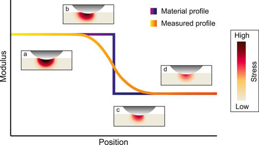
FIGURE 1. Schematic representation of a material that has a step-wise modulus profile and the resulting modulus profile measured by an indentation experiment at several positions across the modulus interface. The four insets a-d display the heterogeneous stress profiles in the material, color coded for the stress, as the material is indented with, in this example, a spherical probe.
Reference [15] characterization, or on the mm-scale or larger for macroscopic probes [16–18]. Previous studies have shown that the extent of mechanical blurring depends on the indentation depth [6] and occurs over an area that is at least three times the contact area of the probe with the substrate [7]. However, the exact dependence of the mechanical response on the probe size and depth remain unknown. Clearly, the characterization of mechanically heterogeneous materials would benefit from a better understanding of the effects of mechanical blurring, and from ways of improving the spatial resolution of mechanical measurements.
A similar problem occurs in optical imaging, where the captured image is a convolution of the real image and the so-called point spread function, which describes the response of the imaging system to a point force and thereby characterizes the degree of blurring. If the point spread function of an optical device is known, deconvolution methods can be used to deblur the signal and increase the image quality [19,20]. In this work, we explore a similar deconvolution strategy for indentation measurements on mechanically heterogeneous materials. We first identify the mechanical analogue of the point spread function. We do this by performing finite element calculations on materials with a known modulus profile E(r), indented by a spherical probe. From the calculated normal force F(r), we obtain an apparent local modulus Ea(r), which we compare to the real modulus E(r) to assess the degree of blurring and to estimate the mechanical point spread function. We find that the blurring is independent of the magnitude of E, which is a prerequisite for deconvolution to be feasible, since the real modulus is unknown. In addition, we find that the deblurring is set by a combination of the probe radius R and the indentation depth δ, which together determine the length scale over which the probe deforms the material. Based on these findings, we then describe two methods to approximate the real modulus profile E from the apparent moduli Ea measured for different values of R and δ.
2 Materials and Methods
2.1 Finite Element Method Simulations
Finite Element simulations were performed using COMSOL Multiphysics 5.4. The 3D stationary structural mechanics module was used to model the indentation of a rigid sphere on a linear elastic substrate. The linear elastic substrate was meshed with small hexahedra swept underneath the spherical probe and coarsely meshed far away from the probe, as shown in Figure 2A, and was solved for 43 k degrees of freedom. Three probe radii were simulated; 400, 500 and 750 µm. The maximum indentation depth was set at δmax = 0.4⋅R and the step size was 4 µm. The linear elastic substrate was modeled with a fixed constraint at the bottom. Contact between the rigid sphere and the elastic substrate was implemented by the penalty method. Further model details are provided in the Supplementary Material (SM). With F obtained from the bottom of the PDMS substrate in the simulations, the apparent modulus Ea was calculated using Hertzian contact theory [8],
where Y is the apparent Young’s modulus, and ν is Poisson’s ratio, which was here taken as 0.45 [21].
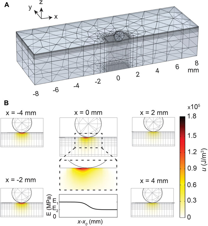
FIGURE 2. (A) Meshing used in the finite element simulations for 1D modulus profiles, where the finely meshed region at the destination moves along with the indentation position. Symmetry in the y-axis is assumed to reduce computation time. (B) Elastic strain energy density, u, distribution for indentations at various positions across the interface for a sigmoidal profile (Eq. 2b) with width w = 10.0 mm, shown with the bottom center plot. The inset of the u profile at the interface, x = 0 mm, shows the heterogeneous u profile across the interface, leading to blurring of the recorded stress response in indentation measurements.
FEM simulations were performed on a total of four profiles: i) a 1-dimensional (1D) stepwise modulus profile ii) 1D sigmoidal profiles with varying widths w iii) 1D wells with various widths w, and iv) 2-dimensional (2D) wells with various widths w2. The modulus profiles were incorporated with a piecewise function in COMSOL’s material section using the following relations:
with E1 > E2, x the position, x0 the position of the interface and H the Heaviside function defined as:
3 Results and Discussion
3.1 Heterogeneity Leads to Asymmetric Stress Profile
FEM simulations are performed on materials with various elastic modulus profiles. Figure 2B shows, for the 1D sigmoidal profile with width w = 10.0 mm, the elastic strain energy density profile
3.2 The Mechanical Point Spread Function
To find the mechanical point spread function that sets the degree of mechanical blurring, a stepwise profile (Eq. 2a) is simulated with FEM. Results in Figures 3A,B show that the mechanical blurring is dependent on R and δ. Likely, this is because R and δ set the contact radius
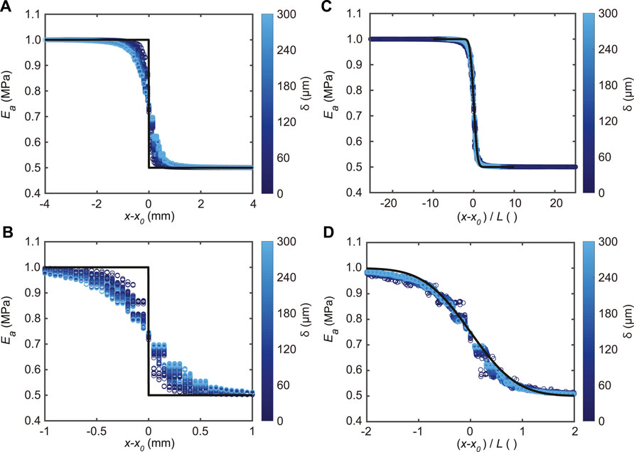
FIGURE 3. FEM simulation data for a step modulus profile for all three probe radii. (A) Ea at all simulated depths δ (color coded) plotted versus the probe position from the interface
Next, we assume that the mechanical blurring function g (r −r′) is a Gaussian function, independent of E:
where L is a characteristic length that determines the degree of blurring. Eq. 3 can be solved analytically for the stepwise profile, by inserting Eq. 2a and Eq. 4 in Eq. 3, resulting in:
with Ec the convolved elastic modulus, which should approximate Ea. By fitting Eq. 5 to Ea from the FEM simulations, the characteristic blurring length L can be determined as a function of R and δ. Indeed, the results presented in Figures 3C,D show a collapse of Ea when x is rescaled with L obtained from these fits, as expected based on Eq. 5. Furthermore, to verify whether L ∼ (R, δ), Figure 4 shows that L can be fitted with
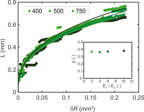
FIGURE 4. The characteristic length L plotted versus the squared contact radius a2 = Rδ for all three probe radii, fitted using
Now that we have obtained the mechanical point spread function and its characteristic blurring length L from the analysis of the blurred step profiles, we investigate whether this can be used to deconvolve apparent moduli measured with indentation to obtain a good approximation of the actual modulus profile of heterogeneous materials. We propose two methods to do this.
3.3 Deconvolution of 1-Dimensional Profiles
The first method to deconvolve a blurred profile is through extrapolation of Ea to L = 0, as at zero indentation depth the material is not deformed and there is no blurring of the mechanical response and, hence, Ea = E in this case. This extrapolation to obtain Ee is shown in Figure 5A for a sigmoidal profile with width w = 10.0 mm, for several probe positions x − x0. An advantage of this extrapolation method to deconvolve Ea into Ee that approximates E is that the precise shape of
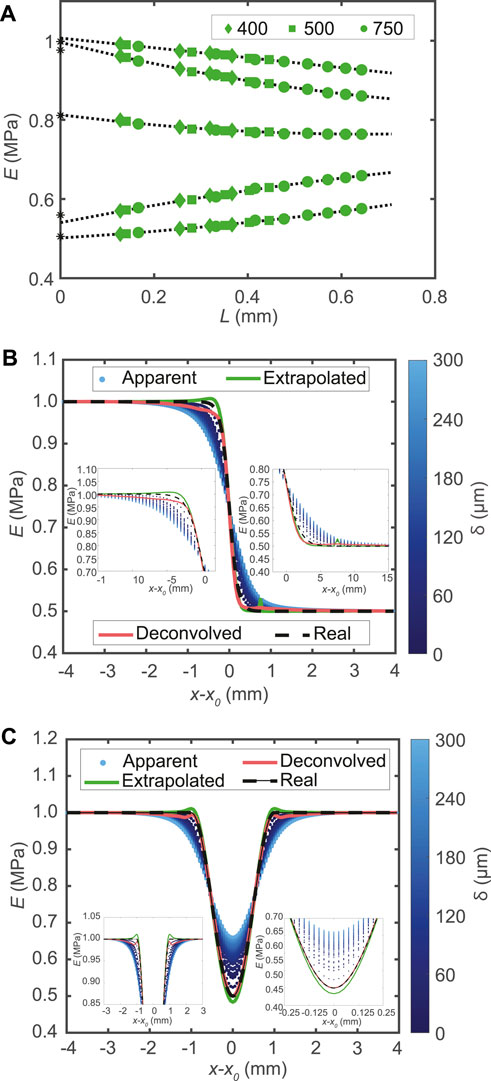
FIGURE 5. (A) Ea plotted versus the L for all three radii simulated for a sigmoidal profile with width w = 10 mm. The data are extrapolated using a second order polynomial fit to give an extrapolated modulus Ee at L = 0, indicated with an asterisk (*), which approximates the local E. The legend shows the symbols corresponding to R. For visualization purpose, every eighth data point is plotted. (B) Elastic moduli plotted versus indentation position around the center of the profile. Insets are zoom-ins. Note that the data shown in both panel (A) and (B) are from a sigmoidal profile with w = 10.0 mm. (C) Elastic moduli plotted as a function of indentation position for the 1D well profiles for w = 2.0 mm, with δ color coded. Insets are zoom-ins.
The second method to deconvolve a blurred profile is accomplished with an algebraic deconvolution approach. First, we write the convolution as a matrix operation:
with G a matrix describing the mechanical blurring. Every row of G contains coefficients that indicate how much the modulus at position r′ contributes to the modulus probed at position r. These coefficients are determined by g (r −r′), of which L is known from the simulations on the 1D steplike profile. To obtain the unknown E from the measured Ea we find a least squares solution to Eq. 6 using an iterative method, Simultaneous Iterative Reconstruction Technique (SIRT) algorithm [22,23]. Further details of this method are provided in the SM.
With the two methods presented above, Ea is extrapolated and deconvolved leading to Ee and Ed, respectively. Ee and Ed convert Ea into an approximation of E, as shown in Figures 5B,C for a sigmoidal profile with width w = 10.0 mm and a well profile with width w = 2.0 mm, respectively. This shows that both presented methods, extrapolation and deconvolution, deblur the stress profile of a heterogeneous elastic profile into an approximation of the actual local elastic modulus.
3.4 Deconvolution of 2-Dimensional Profiles
After demonstrating mechanical deconvolution for 1-dimensional (1D) modulus profiles, simulations were performed to showcase the potential of deconvolving a 2-dimensional (2D) modulus profile. In these simulations, the same meshing was used as for the 1D profiles. Symmetry was assumed across x = x0 and y = y0 and, therefore, a quadrant was modeled to reduce computation time.
The discrepancy between the apparent modulus Ea and the actual modulus profile E, shown in Figures 6A,B, once again demonstrates the necessity for the mechanical deconvolution methodology demonstrated for the 1D profiles. The convolution kernel g and L obtained from the 1D step profile are used to extrapolate and deconvolve Ea.
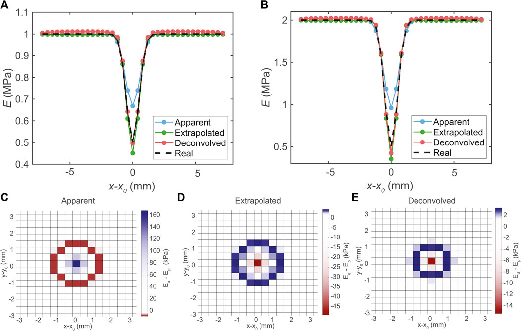
FIGURE 6. Data of two dimensional modulus profiles of a symmetric well, where one quadrant was simulated. (A) All moduli versus probe position plotted as cut line through the center of the well for E1 = 1 MPa and E2 = 0.5 MPa. (B) All moduli versus probe position plotted as cut line through the center of the well for E1 = 2 MPa and E2 = 0.5 MPa. (C) Surface map of Ea − E, (D) Ee − E, and (E) Ed − E for the E1 = 1 MPa and E2 = 0.5 MPa and w2 = 0.5 mm2 profile. Extrapolation and deconvolution is achieved with L obtained from the 1D stepwise profile (see Figure 4).
The results from these simulations show that both the extrapolation and deconvolution methods presented in this work are able to deconvolve both 1D and 2D mechanical profiles, approximating a blurred Ea into profiles close to the actual profile E. Results in Figures 3, 4 confirm that mechanical blurring is at least three times L, as observed by [7]. In addition, simulations on two
3.5 Towards Experimental Validation
Our finite element simulations show how indentation measurements on heterogeneous samples lead to mechanical blurring, and how knowledge of the mechanical point spread function can be used to deconvolve the blurred signal to obtain a more accurate modulus profile, experimental validation is required to transform this proposed method into a reliable practical procedure. To experimentally determine the mechanical point spread function and the associated characteristic length, and to compare this to simulation results shown in Figure 4, a material with a precisely known gradient in modulus is needed, ideally a x-dependent step function in modulus. Indentation measurements on this reference sample then allows the determination of the characteristic length in exactly the same way as described in Section 3.2. Unfortunately, we have not been able to produce such a material of known modulus gradient with the capabilities in our lab, without also creating gradients in the depth-direction or differences in sample height across the modulus step, which made it impossible for us to provide such validation. Our attempts are described in detail in the SM. We hope that this work will inspire others to provide the experimental validation needed to turn our approach into a robust experimental method. We further note that in our approach we have assumed the substrate to be a purely elastic material. While this is justified for elastic solids, such as crosslinked rubbers, care should be taken for viscoelastic soft materials that also have viscous (and therefore rate-dependent) contributions to the mechanical response. Furthermore, since our method is based on linear elasticity, deviations may occur for large indentation depths, where strain hardening may become relevant.
4 Conclusion and Future Outlook
The work presented in this paper shows two methods to transform a blurred and measured Ea towards an expected modulus E in FEM simulations in 1D and 2D. This transformation is achieved by using a characteristic length L, which is found to be a function of δ and R. The methods presented to deconvolve a blurred mechanical profile should work on smaller length as well, for example for mechanical maps obtained using spatially resolved AFM-based force spectroscopy [10,11], provided that the material can still be considered as a flat elastic continuum. For this it is necessary to obtain force-distance curves for each position, so that effective modulus data at the same penetration depth can be compared. To validate the extrapolation and deconvolution methods proposed here experimentally, indentation measurements on a material with a precisely known modulus profile are performed. Unfortunately, we did not succeed in obtaining these, but we hope that future work will demonstrate the potential of mechanical deconvolution. We anticipate that the mechanical deconvolution technique presented here can be used to approximate the actual mechanical heterogeneous material from a blurred stress response, leading to more accurate knowledge of local mechanical properties in for example biological systems [12,14], polymeric materials [6,7,15,26] and meat analogues [27].
Data Availability Statement
The original contributions presented in the study are included in the article/Supplementary Material, further inquiries can be directed to the corresponding author.
Author Contributions
JB, Conceptualization, Simulations, Data processing and analysis, Experiments, Writing—original draft, Writing—review and editing. RK, Conceptualization, Simulations, Data processing, Writing—review and editing. TK, Conceptualization, Experiments, Writing—original draft, Writing—review and editing. JvG, Conceptualization, Data analysis, Writing—original draft, Writing—review and editing.
Conflict of Interest
The authors declare that the research was conducted in the absence of any commercial or financial relationships that could be construed as a potential conflict of interest.
Publisher’s Note
All claims expressed in this article are solely those of the authors and do not necessarily represent those of their affiliated organizations, or those of the publisher, the editors and the reviewers. Any product that may be evaluated in this article, or claim that may be made by its manufacturer, is not guaranteed or endorsed by the publisher.
Acknowledgments
The authors would like to acknowledge the financial support by the European Research Council (Softbreak, grant agreement 682782).
Supplementary Material
The Supplementary Material for this article can be found online at: https://www.frontiersin.org/articles/10.3389/fphy.2021.723768/full#supplementary-material
References
1. Torquato S, Haslach H. Random Heterogeneous Materials: Microstructure and Macroscopic Properties. Appl Mech Rev (2002) 55:B62–B63. doi:10.1115/1.1483342
2. Yin H, Ding Y, Zhai Y, Tan W, Yin X. Orthogonal Programming of Heterogeneous Micro-Mechano-Environments and Geometries in Three-Dimensional Bio-Stereolithography. Nat Commun (2018) 9:4096–7. doi:10.1038/s41467-018-06685-1
3. Kim J, Hanna JA, Byun M, Santangelo CD, Hayward RC. Designing Responsive Buckled Surfaces by Halftone Gel Lithography. Science (2012) 335:1201–5. doi:10.1126/science.1215309
4. Choi KM, Rogers JA. A Photocurable Poly(Dimethylsiloxane) Chemistry Designed for Soft Lithographic Molding and Printing in the Nanometer Regime. J Am Chem Soc (2003) 125:4060–1. doi:10.1021/ja029973k
5. Cortet P-P, Vanel L, Ciliberto S. Super-Arrhenius Dynamics for Sub-Critical Crack Growth in Two-Dimensional Disordered Brittle Media. Europhys Lett (2006) 74:602–8. doi:10.1209/epl/i2005-10572-5
6. Cheng X, Putz KW, Wood CD, Brinson LC. Characterization of Local Elastic Modulus in Confined Polymer Films via Afm Indentation. Macromol Rapid Commun (2015) 36:391–7. doi:10.1002/marc.201400487
7. Bahrami A, Bailly C, Nysten B. Spatial Resolution and Property Contrast in Local Mechanical Mapping of Polymer Blends Using Afm Dynamic Force Spectroscopy. Polymer (2019) 165:180–90. doi:10.1016/j.polymer.2019.01.023
9. Binnig G, Quate CF, Gerber C. Atomic Force Microscope. Phys Rev Lett (1986) 56:930–3. doi:10.1103/physrevlett.56.930
10. Dufrêne YF, Ando T, Garcia R, Alsteens D, Martinez-Martin D, Engel A, et al. Imaging Modes of Atomic Force Microscopy for Application in Molecular and Cell Biology. Nat Nanotech (2017) 12:295–307. doi:10.1038/nnano.2017.45
11. Zhang H, Huang J, Wang Y, Liu R, Huai X, Jiang J, et al. Atomic Force Microscopy for Two-Dimensional Materials: A Tutorial Review. Opt Commun (2018) 406:3–17. doi:10.1016/j.optcom.2017.05.015
12. Rigato A, Rico F, Eghiaian F, Piel M, Scheuring S. Atomic Force Microscopy Mechanical Mapping of Micropatterned Cells Shows Adhesion Geometry-Dependent Mechanical Response on Local and Global Scales. ACS nano (2015) 9:5846–56. doi:10.1021/acsnano.5b00430
13. Efremov YM, Shpichka AI, Kotova SL, Timashev PS. Viscoelastic Mapping of Cells Based on Fast Force Volume and Peakforce Tapping. Soft Matter (2019) 15:5455–63. doi:10.1039/c9sm00711c
14. Rheinlaender J, Schäffer TE. Mapping the Mechanical Stiffness of Live Cells With the Scanning Ion Conductance Microscope. Soft Matter (2013) 9:3230–6. doi:10.1039/c2sm27412d
15. Gu Y, Li M, Wang J, Zhang Z. Characterization of the Interphase in Carbon Fiber/polymer Composites Using a Nanoscale Dynamic Mechanical Imaging Technique. Carbon (2010) 48:3229–35. doi:10.1016/j.carbon.2010.05.008
16. Chan EP, Hu Y, Johnson PM, Suo Z, Stafford CM. Spherical Indentation Testing of Poroelastic Relaxations in Thin Hydrogel Layers. Soft Matter (2012) 8:1492–8. doi:10.1039/c1sm06514a
17. Czerner M, Sanchez Fellay L, Suarez MP, Frontini PM, Fasce LA. Determination of Elastic Modulus of Gelatin Gels by Indentation Experiments. Procedia Mater Sci (2015) 8:287. doi:10.1016/j.mspro.2015.04.075
18. Boots JNM, Fokkink R, Van der Gucht J, Kodger TE. Development of a Multi-Position Indentation Setup: Mapping Soft and Patternable Heterogeneously Crosslinked Polymer Networks. Rev Scientific Instr (2019) 90:015108. doi:10.1063/1.5043628
19. Dougherty G, Kawaf Z. The point Spread Function Revisited: Image Restoration Using 2-d Deconvolution. Radiography (2001) 7:255–62. doi:10.1053/radi.2001.0341
20. Sarder P, Nehorai A. Deconvolution Methods for 3-d Fluorescence Microscopy Images. IEEE Signal Process Mag (2006) 23:32–45. doi:10.1109/msp.2006.1628876
21. Müller A, Wapler MC, Wallrabe U. A Quick and Accurate Method to Determine the Poisson's Ratio and the Coefficient of Thermal Expansion of PDMS. Soft Matter (2019) 15:779–84. doi:10.1039/c8sm02105h
22. Gilbert P. Iterative Methods for the Three-Dimensional Reconstruction of an Object From Projections. J Theor Biol (1972) 36:105–17. doi:10.1016/0022-5193(72)90180-4
23. Wolf D, Lubk A, Lichte H. Weighted Simultaneous Iterative Reconstruction Technique for Single-Axis Tomography. Ultramicroscopy (2014) 136:15–25. doi:10.1016/j.ultramic.2013.07.016
24. Gottlieb D, Shu C-W. On the Gibbs Phenomenon and its Resolution. SIAM Rev (1997) 39:644–68. doi:10.1137/s0036144596301390
25. Kellner E, Dhital B, Kiselev VG, Reisert M. Gibbs-Ringing Artifact Removal Based on Local Subvoxel-Shifts. Magn Reson Med (2016) 76:1574–81. doi:10.1002/mrm.26054
26. Schön P, Bagdi K, Molnár K, Markus P, Pukánszky B, Julius Vancso G. Quantitative Mapping of Elastic Moduli at the Nanoscale in Phase Separated Polyurethanes by Afm. Eur Polym J (2011) 47:692–8. doi:10.1016/j.eurpolymj.2010.09.029
Keywords: deconvolution, heterogeneity, indentation, fintie element model (FEM), length scale
Citation: Boots JNM, Kooi R, Kodger TE and van der Gucht J (2021) Mechanical Deconvolution of Elastic Moduli by Indentation of Mechanically Heterogeneous Materials. Front. Phys. 9:723768. doi: 10.3389/fphy.2021.723768
Received: 11 June 2021; Accepted: 17 August 2021;
Published: 01 September 2021.
Edited by:
Roberto Cerbino, University of Vienna, AustriaReviewed by:
George Petekidis, University of Crete, GreeceBernard Nysten, Université catholique de Louvain, Belgium
Copyright © 2021 Boots, Kooi, Kodger and van der Gucht. This is an open-access article distributed under the terms of the Creative Commons Attribution License (CC BY). The use, distribution or reproduction in other forums is permitted, provided the original author(s) and the copyright owner(s) are credited and that the original publication in this journal is cited, in accordance with accepted academic practice. No use, distribution or reproduction is permitted which does not comply with these terms.
*Correspondence: J. van der Gucht, amFzcGVyLnZhbmRlcmd1Y2h0QHd1ci5ubA==