 Zhenbo Wei1
 Zhe Zhang1*Li Jiang1Yang Yang1Chenyuan Chang1Yufei Feng1Runze Qi1
 Qiushi Huang1Wensheng Yan2Chun Xie3Zhanshan Wang1
- 1MOE Key Laboratory of Advanced Micro-Structured Materials, Institute of Precision Optical Engineering (IPOE), School of Physics Science and Engineering, Tongji University, Shanghai, China
- 2National Synchrotron Radiation Laboratory, University of Science and Technology of China, Hefei, China
- 3Sino-German College of Applied Sciences, Tongji University, Shanghai, China
NiV/B4C multilayers with a small d-spacing are suitable for multilayer monochromator working at a photon energy region from 5 to 8 keV, or photon energy region from 10 to 100 keV. To investigate the influence of background pressure during fabrication, NiV/B4C multilayers with a d-spacing of 3.0 nm were fabricated by magnetron sputtering with different background pressures. The grazing incidence x-ray reflectivity (GIXR) and transmission electron microscopy (TEM) measurement illustrated the structural change that happened in NiV/B4C multilayers when background pressure is high. The electron dispersive x-ray spectroscopy (EDX) of NiV/B4C multilayer deposited with a high background pressure suggests a gradient distribution of oxygen, which corresponds to the gradient thickness change. The detailed x-ray absorption near edge spectroscopy (XANES) comparison of NiV/B4C multilayers, NiV coating, and B4C coating showed the chemical state change induced by background pressure. We concluded that during the deposition, vanadium oxide promoted the oxidation of boron. In order to fabricate a good performance of NiV/B4C multilayers, the background pressure needs lower than 1 × 10⁻⁴ Pa.
1 Introduction
Multilayer interference coating is an important optics in the hard x-ray region, which enables the reflection of the short-wavelength light beyond the total external reflection region, and chooses a narrow-band spectrum from the white light radiation. Thus, it is widely used in advanced imaging, spectroscopy, and monochromator systems for synchrotron radiation facilities and astronomical observation projects [1–3]. As photon energy requirement of synchrotron radiation facilities and space telescopes extends to several tens of kiloelectron volts, the multilayer working at such wavelength region requires an extremely small d-spacing which is less than 3.0 nm [4–7]. This makes the x-ray reflectance very sensitive to the interface and surface quality of the multilayer, which also needs the more precise control of fabrication and the more suitable selection of materials. As for fabrication, magnetron sputtering has been proved as an effective technique for fabricating small d-spacing multilayers, which has the good controllability of the process and the relatively low cost of the instrument [8]. For materials selection, more and more researchers began using a compound to replace the elementary substance [9, 10].
In the hard x-ray region, a multilayer monochromator has the advantage of a large spectral bandwidth and high reflectance, which can provide one or two orders of magnitude higher integral flux than a crystal monochromator [11]. Nickel is one of the ideal absorption materials in the whole hard x-ray region, except for 8.3 keV (Ni K-edge) [12, 13], but nickel is a magnetic material, which is not compatible with magnetron sputtering for small d-spacing multilayers. For solving this problem, a nonmagnetic alloy was made up of 93% nickel, and 7% vanadium has been proposed (in the following article, we will use NiV instead of the more correct Ni93V7). At the beginning, NiV has been suggested by Danish Space Research Institute as a potential candidate for hard x-ray telescope. [14] Because compared with tungsten and platinum, there was no absorption line for NiV at the photo energy range from 20 to 200 keV [9]. Until 2017, NiV was first used as a multilayer monochromator in European Synchrotron Radiation Facility (ESRF) [15]. Given the higher reflectivity and integral flux, the NiV/B4C combination was thus chosen as the material of choice for a monochromator working at 8 keV and around 20 keV [16–18]. Apart from that, the detailed studies on NiV/B4C multilayers were really limited, especially on how to fabricate this promising X-ray multilayer mirror.
During the magnetron sputtering process, there are a lot of factors that will influence the final performance of multilayers. For example, the pressure of working gas (typically argon) impacts stress and the layer density, and the speed of the spin motion of the substrate during deposition influences the uniformity of the coating. The background pressure is also one of the parameters that needs to be characterized and precisely controlled. It is reported that the background pressures affect the stress and layer morphology of layers [19, 20]. The residual gas in vacuum chamber will react with sputtering atoms and alter the refractive index contrast between multilayer materials, furthermore changing the film structure by the formation of compounds and impacting the interface quality [21, 22]. In order to understand the background pressure effect on the growth of the NiV/B4C multilayer, a comparative study of the NiV/B4C multilayers fabricated with different background pressures was performed in this paper. The multilayer structure, layer morphology, and chemical state of the multilayers were investigated and discussed systematically.
2 Experiments
In order to realize the application of NiV/B4C multilayers in hard x-ray telescope or multilayer monochromator, the multilayer d-spacing in this research was set to d = 3.0 nm and the thickness ratio γ = dNiV/d = 0.6. The number of bilayers was N = 60 to test the period drift of multilayer. The NiV/B4C multilayers were fabricated by direct current magnetron sputtering technique. The B4C (purity 99.5%) target was used at a constant power of 80 W, the NiV target (Ni:V = 93:7, purity 99.99%) at 20 W. Both targets have a diameter of 4 inches. The distances from substrate to target are 8.5 and 9.0 cm, respectively to NiV and B4C. During the deposition, high-purity argon (99.999%) was used as the working gas at a pressure of 0.16 Pa, for keeping a relatively high kinetic energy of the deposited atoms and, thus, to form smooth interfaces, and the flow rate for Ar is 8 sccm. The multilayers were deposited on superpolished Si (100) wafers (20 mm × 20 mm) with a root-mean-square roughness of 0.2 nm (1 × 1 μm2 atomic force microscope scan). The individual layer thicknesses in the multilayer were, thus, adjusted by controlling the sputtering time independently over each target. The background pressures, which arise from residual air in the deposition chamber, were measured before inflating Ar. In each case, the chamber was pumped from the normal air condition to the background pressures of 4 × 10⁻⁴, 2 × 10⁻⁴, 1 × 10⁻⁴, 8 × 10⁻⁵, 4 × 10⁻⁵, and 2 × 10⁻⁵ Pa, by using a combination of a turbomolecular pump and a mechanical pump. The fabricated multilayers are symbolized as S-4 × 10⁻⁴, S-2 × 10⁻⁴, S-1 × 10⁻⁴, S-8 × 10⁻⁵, S-4 × 10⁻⁵, and S-2 × 10⁻⁵ Pa, respectively. Except for background pressure, all the deposition parameters were the same in all cases.
The grazing incidence x-ray reflectivity (GIXR) measurement used a laboratory-based diffractometer (Bede, Durham, UK) with the Cu Kα line as the source (λ = 0.154 nm). Fits of the GIXR curve were performed using the Bede Refs software [23]. The information of the individual layer thickness and interface width was determined from the fitting.
High-resolution transmission electron microscopy (TEM) measurements were made to compare the microstructure and layer morphology of the two samples deposited with different background pressures. The samples were prepared by focused ion beam and observed by FEI Talos F200X (FEI, Hillsboro, OR, United States). The elemental composition of the layers was further measured by energy dispersive x-ray spectroscopy (EDX) during the TEM measurements. Mapping and one-dimensional line scans across several bilayers were performed to measure the composition depth profiles of the different elements.
X‐ray absorption near‐edge structure (XANES) spectroscopy was commonly used to probe the local atomic structure around specific elements in films and often used as a fingerprint of the changes in the coordination numbers of elements [24–26]. XANES measurements were conducted after fabrication at the Beamline U12b at the National Synchrotron Radiation Laboratory (NSRL) in the total electron yield (TEY) mode by collecting sample drain currents under a vacuum, which was greater than 5 × 10⁻⁸ Pa. The beam from a bending magnet was monochromatized with a varied line‐spacing plane grating and refocused using a toroidal mirror. An energy range from 100 to 1,000 eV was used with an energy resolution of approximately 0.2 eV. All XANES spectra were measured using the process of normalization by considering the low and high photon energy parts of the spectra far from the threshold [26, 27].
3 Results and Discussion
3.1 Grazing Incidence X-Ray Reflectivity Measurement Analysis
The GIXR measurements of as-deposited samples are shown in Figure 1A. The different colors represent different background pressures. As the background pressure becomes lower, the Bragg peaks become narrower, which indicates that the multilayer sample has less d-spacing drift from the surface to the substrate. Besides the width of Bragg peaks, the positions of Bragg peaks also changed with different background pressures. With the background pressure decreasing from 4 × 10⁻⁴ to 1 × 10⁻⁴ Pa, the grazing angles of Bragg peaks kept increasing, which means the d-spacing of multilayer becomes thinner. When the background pressure reached 8 × 10⁻⁵ Pa and further lower, the grazing angle of Bragg peaks did not change, indicating that the d-spacings of different samples became consistent with varied background pressures. Figure 1B shows the fitted result of NiV/B4C multilayer deposited with background pressure of 4 × 10⁻⁵ Pa. The fitted curve matched very well with GIXR measurement result, which means the fitted model is in agreement with the deposited layer structure, and the bandwidth of the measured Bragg peaks is similar with the fitted curve, which indicates the good uniformity of 60 bilayers. The fitted values of two individual layers are also shown in this figure; the thicknesses of NiV and B4C were 1.65 and 1.10 nm, respectively. The average interface width for the two kinds of materials were 0.29 nm (NiV) and 0.31 nm (B4C).
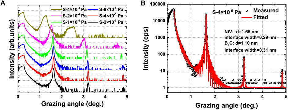
FIGURE 1. (A) Grazing incidence x-ray reflectivity (GIXR) measurement of NiV/B4C multilayer deposited with different background pressures. (B) GIXR measurement and fitted result of NiV/B4C multilayer deposited with a background pressure of 4 × 10⁻⁵ Pa.
Based on GIXR measurements, we can assume that the change in layer structure happened in NiV/B4C multilayers when the background pressure was higher than 1 × 10⁻⁴ Pa because all of the parameters for GIXR measurement and deposition are the same except for background pressure. There are two most possible reasons for broader Bragg peaks, one is the gradient d-spacing change in a multilayer, and the other one is the gradient refractive index change. How did the background pressure induce a gradient change in multilayer? We need further analysis to investigate how the change happened in NiV/B4C multilayers.
3.2 Transmission Electron Microscope Analysis
The cross-sectional TEM images and selected area electron diffraction (SAED) patterns of NiV/B4C multilayer deposited with different background pressures are shown in Figure 2. The bright layers are B4C, and the dark layers are NiV. Based on low-magnification images, we found that the total thickness of sample S-4 × 10⁻⁴ Pa was 47.7 nm thicker than that of sample S-4 × 10⁻⁵ Pa, which confirmed the structural change induced by background pressure. In Figures 2A,B, both samples have flat layers, but the interfaces of sample S-4 × 10⁻⁵ Pa are shaper. In the high-resolution images (Figures 2C,D), it can be easily found that the individual d-spacing of S-4 × 10⁻⁴ Pa was different from S-4 × 10⁻⁵ Pa, indicating the different positions of Bragg peak in Figure 1A. Based on further analysis of high-resolution images, we found that the d-spacing of sample S-4 × 10⁻⁴ Pa changed gradually from the surface to the substrate, which range from 3.38 to 4.18 nm. Such a gradient d-spacing will cause the broadened Bragg peak as shown in Figure 1A. The thicker layers were close to the substrate, and the B4C layers changed much more than the NiV layers. As for sample S-4 × 10⁻⁵ Pa, the d-spacing was constant for the whole multilayer. The d-spacing was 2.79 nm measured from high-resolution images, which was close to the fitted result (shown in Figure 1B) of GIXR measurement and indicating that the fitted model was similar with the actual structure. SAED images were recorded with a large electron beam covering several tens of bilayers of the NiV/B4C multilayers. Figures 2E,F display the SAED images of samples S-4 × 10⁻⁴ and S-4 × 10⁻⁵ Pa, respectively. Both of them only have a diffraction pattern coming from the multilayer structure indicating an amorphous layer structure in these samples [7]. However, compared with S-4 × 10⁻⁴ Pa, the electron diffraction pattern of S-4 × 10⁻⁵ Pa is more regular, which means that the layer structure in S-4 × 10⁻⁵ Pa is more uniform.
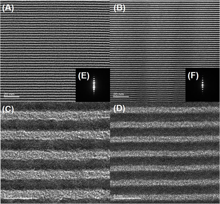
FIGURE 2. Transmission electron microscopy (TEM) and selected area electron diffraction (SAED) images of the NiV/B4C multilayers fabricated with background pressures of 4 × 10⁻⁴ Pa (A,C,E) and 4 × 10⁻⁵ Pa (B,D,F).
To our knowledge, the background pressure may cause the change in deposition rate for sputtering materials, but would not induce a gradient d-spacing in multilayers. Therefore, the only physical reason that can explain the formation of a gradient d-spacing is the element composition change in the multilayer due to the residual gas in the chamber [21, 22]. The element composition change will also cause the refractive index change. Analysis of this hypothesis will be performed in the following section.
3.3 Energy-Dispersive X-Ray Spectroscopy Analysis
The higher background pressure means more residual gas stayed in the chamber. During the deposition process, some gas would be activated by plasma environment, then forming compounds with sputtering particles. In order to analyze the elemental composition of samples S-4 × 10⁻⁴ and S-4 × 10⁻⁵ Pa, EDX mapping and one-dimensional line scans across several bilayers were performed during the TEM measurement. In our work, the EDX measurements were performed to characterize elements of boron (B), carbon (C), nitrogen (N), oxygen (O), nickel (Ni), and vanadium (V).
The EDX measurement allowed to approximately determine the atomic concentration of different elements. In Figures 3A,B, the high angle annular dark field (HAADF) images are combined with element mapping images, for observing the element distribution in samples S-4 × 10⁻⁴ and S-4 × 10⁻⁵ Pa, respectively. Vanadium and nitrogen mapping images are not included in these figures because of the low atomic concentration (vanadium is only 7% in NiV target). In HAADF images, the bright layers are NiV and the dark layers are B4C. As shown in Figures 3A,B, the Ni and C element distributions are both in accordance with HAADF images; the main difference happened in O and B elements distributions. In sample S-4 × 10⁻⁴ Pa, oxygen distribution exhibits the layer structure, and these layers are in keeping with B4C layers, which means a lot of oxygen atoms stayed in the B4C layers. On the contrary, the oxygen distribution in sample S-4 × 10⁻⁵ Pa does not have such an obvious layer structure. Because the sensitivity for boron detection in the EDX measurement is not good, the boron distributions in both samples are not as clear as the other elements, but in sample S-4 × 10⁻⁵ Pa, boron distribution seems to have a blurred layer structure compared with S-4 × 10⁻⁴ Pa.

FIGURE 3. Electron-dispersive x-ray spectroscopy (EDX) mapping-scan and line-scan (from surface to substrate) measurements of chemical elements in the NiV/B4C multilayers fabricated with background pressures of 4 × 10⁻⁴ Pa (A,C) and 4 × 10⁻⁵ Pa (B,D).
The detailed one-dimensional line scans of samples S-4 × 10⁻⁴ and S-4 × 10⁻⁵ Pa are shown in Figures 3C,D. In sample S-4 × 10⁻⁴ Pa (Figure 3C), except for boron, the other elements both have a periodic oscillation of concentration. The element with the most remarkable profile is oxygen, the average atomic concentration of oxygen in the whole scan area is more than 30%, and from the surface to substrate, the atomic concentration of oxygen keeps increasing, which is consistent with the d-spacing change in sample S-4 × 10⁻⁴ Pa. In sample S-4 × 10⁻⁵ Pa (Figure 3D), all measured elements have a periodic oscillation of concentration, which further illustrates that sample S-4 × 10⁻⁵ Pa has a uniform layer structure.
According to the EDX measurement results, we find that oxygen is the main reason for the gradient d-spacing in NiV/B4C multilayer. When the deposition process happened with a higher background pressure, the oxygen in residual gas would interact with boron and carbon atoms. Then the tri-element compound layer replaces B4C and causes the volume expansion. As the deposition time went by, the oxygen concentration in the chamber becomes lower, the tri-element compound layer also becomes thinner, which means the volume of the tri-element compound is proportion to the concentration of oxygen. Due to this phenomenon, the d-spacing of the multilayer is gradually thinning from the substrate to the surface. This gradient change is consistent with the results obtained from the GIXR and TEM measurements. Except for the volume change, the refractive index of this tri-element compound layer may also change with the oxygen concentration. When the deposition process happened with a lower background pressure, the oxygen concentration also lower in the residual gas. Although the oxygen still has the opportunity to interact with sputtering particles (which has been proved in our previous work [4]), the lower concentration of oxygen would not cause the obvious thickness change in the boron carbide layer, which promote the uniformity between bilayers (as shown in Figures 1B, 3D).
3.4 X-Ray Absorption Near-Edge Structure Spectroscopy Analysis
In order to further explore the chemical change caused by different background pressures, XANES measurements have been implemented in several samples (S-4 × 10⁻⁴ , S-1 × 10⁻⁴, S-8 × 10⁻⁵, S-4 × 10⁻⁵, S-2 × 10⁻⁵ Pa). Except for multilayer samples, we also fabricated two single-layer samples for comparison. One is NiV coating marked as S-NiV in the following part, and this sample was deposited with a background pressure of 1 × 10⁻⁴ Pa. Another one is B4C coating marked as S-B4C, which was deposited with a background pressure of 6 × 10⁻⁵ Pa. These two background pressure values were suggested by GIXR and TEM measurement results to mitigate the influence caused by residual gas. The thicknesses of S-NiV and S-B4C are 16 and 35 nm, respectively, which fitted the GIXR measurements. Because the purpose for this study is investigating the influence from background pressure, pre- and post-edge normalizations have not been carried out during the data analysis in this paper.
3.4.1 B K-Edge X-Ray Absorption Near-Edge Spectroscopy
The B K-edge absorption spectra of five NiV/B4C MLs are presented in Figure 4A. There are three prominent features in the B-K absorption spectra, which are marked as a, b, and c, respectively. Features a and b are both narrow peaks appearing at photon energies of ∼192.8 and ∼194.2 eV. Feature c looks like a broad bump in the high-energy regime (195–205 eV). The narrow edge peak a (192.8 eV) occurs due to the transition of a B 1s electron to the unoccupied B 2p π* state. According to Jiménez’ s research, this feature seems related to inter-icosahedral B–B bonds [28]. The other narrow peak b (194.2 eV) is due to transition of a B 1s electron to the unoccupied B 2p π* state in B in the presence of oxygen [29, 30]. The feature c is due to the transition of B 1s electrons to the unoccupied B σ* states, which corresponds to bonding within the C–B–C chain structure [31, 32].
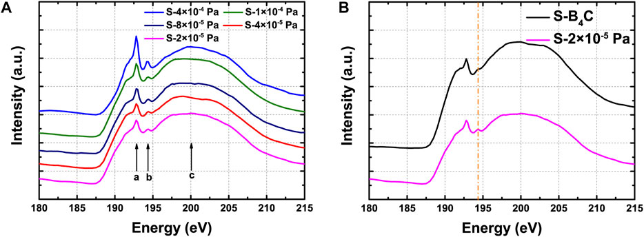
FIGURE 4. The B K-edge X-ray absorption near-edge spectroscopy (XANES) spectra of different samples: (A) NiV/B4C MLs deposited with different background pressures (S-4 × 10⁻⁴, S-1 × 10⁻⁴, S-8 × 10⁻⁵, S-4 × 10⁻⁵, and S-2 × 10⁻⁵ Pa). (B) NiV/B4C ML deposited with 2 × 10⁻⁵ Pa and B4C coating deposited with 6 × 10⁻⁵ Pa.
With the background pressure changing from 4 × 10⁻⁴ to 2 × 10⁻⁵ Pa, the relative intensities of features a and b become lower, but the intensity of feature c becomes higher. This result indicates the sputtered boron atoms tend to bond with carbon atoms to form a C–B–C chain with a lower background pressure in a vacuum chamber. These C–B–C chains mainly stay in boron carbide layers and make the boron carbide layer have a regular layer structure, which is proven by boron distribution in Figure 3D, but with a higher background pressure, the oxygen concentration becomes higher, the sputtered boron atoms seem to prefer to combine with oxygen atoms. Therefore, the oxygen atoms destroyed parts of the C–B–C chains and formed a lot of B–O bonds. These B–O bonds stayed in boron carbide layers and formed a tri-element compound layer, which is consistent with the oxygen distribution in Figure 3C. The increased B–B bonds may come from some dissociated boron in NiV/B4C ML [33], which results in an aperiodic boron distribution shown in EDX measurements (Figure 3C).
In Figure 4B, the B K-edge absorption spectra of NiV/B4C ML and B4C coating are presented. The main difference between these two curves is the feature b, which is marked by an orange line. The background pressure during the deposition of S-B4C (6 × 10⁻⁵ Pa) is higher than S6 (2 × 10⁻⁵ Pa), but S6 has a higher intensity at feature b, which means the boron in NiV/B4C ML is easier to bond with oxygen. We suspect in NiV/B4C ML that boron was excited by other elements then tend to combine with oxygen. There is a material worked as catalyst [34] during the deposition of NiV/B4C ML.
3.4.2 V L-Edge and O K-Edge X-Ray Absorption Near-Edge Spectroscopy
The V L-edge and O K-edge XANES were measured to investigate the catalysis of the boron oxidation that happened in NiV/B4C ML. The V L-edge and O K-edge absorption spectra of samples S-NiV, S-1 × 10⁻⁴ Pa and S-B4C are presented in Figure 5A. S-NiV and S-1 × 10⁻⁴ Pa were deposited with the same background pressure. There are much more features in V L-edge and O K-edge XANES compared with B K-edge. Each feature is labeled with different letters shown in Figure 5A.
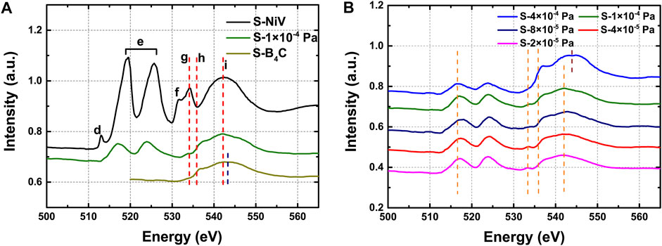
FIGURE 5. The V L-edge and O K-edge XANES spectra of different samples. (A) NiV/B4C ML and NiV coating deposited with 1 × 10⁻⁴ Pa, B4C coating deposited with 6 × 10⁻⁵ Pa. (B) NiV/B4C MLs deposited with different background pressures (S-4 × 10⁻⁴ , S-1 × 10⁻⁴, S-8 × 10⁻⁵, S-4 × 10⁻⁵, and S-2 × 10⁻⁵ Pa).
In the spectrum of S-NiV, the most distinct dual-peak feature (marked as e) at the region from 519.6 eV (left peak; known as L3-edge) to 525.7 eV (right peak; known as L2-edge), which correspond to the electronic transitions from the V 2p3/2 and V 2p1/2 core levels, respectively, to the unoccupied 3d levels [35]. Based on previous researches, the spectrum of S-NiV is similar with the V2O5, especially that they both have the small peak (peak d) besides the V L3-edge [36]. This small peak (centered at 513.0 eV) can be assigned to the splitting of the unoccupied V 3d orbitals, which also indicates that the V2O5-liked structured formed in the S-NiV sample during the deposition. The features located at the energy region higher than 530.0 eV originated from the electronic transitions from O 1s to O 2p hybridized V 3d orbitals and are known to provide valuable information on the crystal structure, local symmetry of metal ions, and ligand-field effects [37, 38]. In an octahedral environment, the metal eg (dz2, dx2—y2) orbitals are pointed directly toward the O ligands to form strongly bonded σ bonds with the O pz orbital. On the other hand, the metal t2g (dxy, dxz, dyz) orbitals point between the O ligands and make weak π bonds with O px and py [38]. In Figure 5A, peak f (531.7 eV) and peak g (534.1 eV) correspond to eg and t2g, respectively. The intensity of eg is lower than t2g, indicating that the V2O5-liked structured formed in S-NiV is closer to tetrahedrally coordinated compounds rather than octahedrally coordinated compounds [38, 39]. The broad feature i is due to the transition of O 1s electrons to the unoccupied O σ* states [38, 40].
Compared with S-NiV, the absorption spectrum of S-1 × 10⁻⁴ Pa shows less features. The dual-peak feature has a blue shift, L2-edge centered at 517.0 eV, and L3-edge changed to 523.9 eV, which means that the oxidation state of vanadium changed [41]. The position of features g and i are consistent with S-NiV, indicating that the coordinated structure around O atoms is similar, but the features d and f become absent, which means that the vanadium oxide in S-1 × 10⁻⁴ Pa is amorphous or highly disordered [36]. The O K-edge absorption spectrum of S-B4C only has two features, one looks like a shoulder around 535.9 eV (labeled as h), which is also shown in the curve of S-1 × 10⁻⁴ Pa. The other one is also a broad feature, but peak has a little bit of shift compared with feature i in S-1 × 10⁻⁴ Pa and S-NiV. This shift is because the local atomic structure around O atoms was changed in different samples.
In Figure 5B, we compared NiV/B4C MLs deposited with different background pressures. There are four orange dash lines corresponding to features e, g, h, and i (shown in Figure 5A), respectively. With the background pressure becoming lower, the L3-edge has a gradual blue shift, which means that the oxidation state of vanadium keep changing toward a higher oxidation state. All the five curves both have feature h, and this feature is located at the same position, but the relative intensity of feature h also becomes lower as the background pressure changed. This is the same with feature b shown in B K-edge XANES because these two features are both related to B–O bonds. As for features g and i, the curve of S-4 × 10⁻⁴ Pa is totally different with other samples. The feature g in the curve of S-4 × 10⁻⁴ Pa is absent, and feature i has a shift compared with others. This shift is also shown in Figure 5A. Except for S-4 × 10⁻⁴ Pa, in the other samples, features g and i are both located at the same position. The relative intensity of feature i has a slight change with the changed concentration of oxygen in a vacuum chamber. On the contrary, the relative intensity of feature g seems to become higher when oxygen atoms become fewer, which means the structure of vanadium oxide tends to become ordered with less oxidation of boron.
Based on the comparison of the V L-edge and O K-edge XANES of different samples, we can conclude that several facts had happened during the magnetron sputtering deposition process: 1) Vanadium will form vanadium oxide during the deposition even with a background pressure of 2 × 10⁻⁵ Pa, and vanadium oxide is a well-known catalyst [34], which enhanced the combination of boron and oxygen. 2) As the combination of boron and oxygen has been catalyzed, the boron will grab more and more oxygen atoms, which will prevent the vanadium oxide from going to its highest oxidation state. 3) When the background pressure is lower than 1 × 10⁻⁴ Pa, the local atomic structure around O atoms does not change a lot, which means the chemical state and the layer structure are relatively stable in NiV/B4C ML.
3.4.3 Nickel L-Edge X-Ray Absorption Near-Edge Spectroscopy
The Ni L‐edge x‐ray absorption near‐edge structure spectra were measured to analyze the change in local atomic structure around the nickel atoms. The Ni L-edge absorption spectra of five NiV/B4C MLs are presented in Figure 6A. There are two features in the measurement results, marked as j and k. The feature j centered at 857.3 eV (assigned at Ni L3-edge) and the feature k located at 875.0 eV (assigned at Ni L2-edge), which correspond to the electronic transitions from the Ni 2p3/2 and 2p1/2 ground states, respectively, to the unoccupied Ni 3d final states [42, 43]. As shown in Figure 6A, the relative intensities and positions of the different samples are the same, which means the background pressure does not cause any change in the Ni element in NiV/B4C ML.
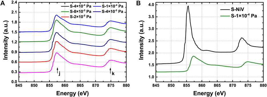
FIGURE 6. The nickel (Ni) L-edge XANES spectra of different samples. (A) NiV/B4C MLs deposited with different background pressures (S-4 × 10⁻⁴ , S-1 × 10⁻⁴, S-8 × 10⁻⁵, S-4 × 10⁻⁵, and S-2 × 10⁻⁵ Pa). (B) NiV/B4C ML and NiV coating both deposited with 1 × 10⁻⁴ Pa.
In Figure 6B, we compared the Ni L-edge absorption spectra of S-NiV and S-1 × 10⁻⁴ Pa. We found that features j and k both have a blue shift (∼1.9 eV) in the curve of S-NiV. In the NiV coating, only vanadium and oxygen atoms are around Ni atoms, but in a multilayer, Ni atoms also adhere to the interface between NiV and B4C layers. We suspected that the presence of interface caused the change in local atomic structure around Ni atoms, which caused the shift of Ni L-edge.
4 Conclusion
NiV/B4C multilayers fabricated with different background pressures were studied comparatively. When the background pressure was higher than 1 × 10⁻⁴ Pa, an obvious structural change has been found in multilayers. This structural change is mainly shown in the thickness change in the B4C layer. According to the EDX measurement, the thickness change is directly proportionate to the oxygen concentration in a vacuum chamber. Therefore, a gradient d-spacing change happened in a sample deposited with a high background pressure. Such a change will make the reflectivity spectrum broadened, which causes a severe performance loss when using an NiV/B4C combination for a multilayer monochromator. XANES has been applied to further investigate the chemical change that happened in NiV/B4C multilayers deposited with different background pressures. The oxidation of vanadium and boron has been found in all samples, which means the oxidation of active elements is inevitable during magnetron sputtering process, as long as the oxygen atoms stay in the vacuum chamber. After comparing the NiV/B4C multilayer, NiV coating, and B4C coating, an interesting phenomenon has been found. When the oxygen concentration is lower in the vacuum chamber, the vanadium oxidates work as a catalyst, which promotes the combination of boron and oxygen, but in the higher oxygen concentration environment, boron will “rob” the majority of oxygen atoms, which prevents the oxidation state of vanadium oxide toward its highest oxidation state. Besides the NiV/B4C multilayers, a similar catalysis has been found in the Pd/B4C multilayers [27]. Due to the catalysis, the ultrathin Pd/B4C multilayers degraded rapidly when stored in air. Therefore, the lifetime and stability of NiV/B4C multilayers is worth to be further studied. In this study, the structural and chemical changes both suggest that the NiV/B4C multilayers need to fabricate with a background pressure lower than 1 × 10⁻⁴ Pa. Besides, the chemical state change found in this work can also provide useful guidance for further development and fabrication of NiV/B4C multilayers.
Data Availability Statement
The raw data supporting the conclusion of this article will be made available by the authors, without undue reservation.
Author Contributions
ZZ and ZWa conceived and designed the research work. QH and RQ carried out the simulations. ZWe, YY and LJ prepared the samples. ZWe, ZZ, YF and CC analyzed the data. ZWe and ZZ wrote the paper. WY, CX and ZWa contributed to the helpful discussions for the research and modifications to the article. All authors have read and agreed to the published version of the manuscript.
Funding
This research was funded by the National Natural Science Foundation of China (Grant Nos. 12075170, 12003016 and U2030111(NSAF)).
Conflict of Interest
The authors declare that the research was conducted in the absence of any commercial or financial relationships that could be construed as a potential conflict of interest.
Publisher’s Note
All claims expressed in this article are solely those of the authors and do not necessarily represent those of their affiliated organizations, or those of the publisher, the editors, and the reviewers. Any product that may be evaluated in this article, or claim that may be made by its manufacturer, is not guaranteed nor endorsed by the publisher.
Acknowledgments
All authors would like to acknowledge the beamline MCD-A and MCD-B (Soochow Beamline for Energy Materials) at NSRL.
References
1. Huang Q, Medvedev V, Van de Kruijs R, Yakshin A, Louis E, Bijkerk F. Spectral Tailoring of Nanoscale EUV and Soft X-Ray Multilayer Optics. Appl Phys Rev (2017) 4:011104. doi:10.1063/1.4978290
2. Barrett R, Baker R, Cloetens P, Morawe C, Tucoulou R, Vivo A. Reflective Optics for Hard X-Ray Nanofocusing Applications at the ESRF. Synchrotron Radiat News (2016) 29:10–5. doi:10.1080/08940886.2016.1198668
3. Windt DL. Advancements in Hard X-Ray Multilayers for X-Ray Astronomy. Opt Euv, X-ray, Gamma-ray Astron (2015) VII:960396031C. doi:10.1117/12.2187481
4. Huang Q, Liu Y, Yang Y, Qi R, Feng Y, Kozhevnikov IV, et al. Nitridated Ru/B4C Multilayer Mirrors with Improved Interface Structure, Zero Stress, and Enhanced Hard X-ray Reflectance. Opt Express (2018) 26:21803. doi:10.1364/oe.26.021803
5. Liu Y, Huang Q, Qi R, Xiao L, Zhang Z, Li W, et al. Microstructure Evolution and Hard X-Ray Reflectance of Ultrathin Ru/C Multilayer Mirrors with Different Layer Thicknesses. Mater Res Express (2021) 8:026401. doi:10.1088/2053-1591/abdf13
6. Windt DL, Donguy S, Hailey CJ, Koglin JE, Honkimaki V, Ziegler E, et al. Optical Constants for Hard X-Ray Multilayers over the Energy Range E = 35 - 180 KeV. Proc SPIEOptics for EUV, X-Ray, and Gamma-Ray Astronomy (2004) 5168:35–40. doi:10.1117/12.505886
7. Ni H, Huang Q, Liu G, Qi R, Zhang Z, Li X, et al. Comparative Study of Pd/B4C X-Ray Multilayer Mirrors Fabricated by Magnetron Sputtering with Kr and Ar Gas. Materials (2020) 13:4504–10. doi:10.3390/ma13204504
8. Louis E, Yakshin AE, Tsarfati T, Bijkerk F. Nanometer Interface and Materials Control for Multilayer EUV-Optical Applications. Prog Surf Sci (2011) 86:255–94. doi:10.1016/j.progsurf.2011.08.001
9. Jensen CP, Madsen KK, Christensen FE. Investigation of New Material Combinations for Hard X-Ray Telescope Designs. Sp Telesc Instrum Ultrav Gamma Ray (2006) 6266:626612. doi:10.1117/12.673180
10. Christensen FE, Jensen CP, Madsen KK, Pivovaroff MJ, Chen H, Dariel A, . Novel Multilayer Designs for Future Hard X-Ray Missions. Sp Telesc Instrum Ultrav Gamma Ray (2006) 6266:626611. doi:10.1117/12.673181
11. Rack A, Weitkamp T, Riotte M, Grigoriev D, Rack T, Helfen L, et al. Comparative Study of Multilayers Used in Monochromators for Synchrotron-Based Coherent Hard X-Ray Imaging. J Synchrotron Radiat (2010) 17:496–510. doi:10.1107/S0909049510011623
12. Dietsch R, Braun S, Holz T, Mai H, Scholz R, Bruegemann L. Multilayer X-ray Optics for Energies E > 8 keV and Their Application in X-ray Analysis. Proc SPIE (2000) 4144:137–47. doi:10.1117/12.405887
13. Ivan A, Bruni RJ, Byun KW, Gorenstein P, Romaine SE. Hard X-Ray Multilayers: A Study of Different Material Systems. Proc Spie: Adv X-Ray Opt (2001) 4145:72–9. doi:10.1117/12.411622
14. Chen CMH, Christensen FE, Harrison FA, Mao PH, Windt DL. Design of a Soft Gamma-Ray Focusing Telescope for the Study of Nuclear Lines. X-ray Gamma-ray Telesc Instr Astron (2003) 4851:1356. doi:10.1117/12.461419
15. Morawe C, Carau D, Peffen J-C. Double Multilayer Monochromators for Upgraded ESRF Beamlines. Proc Spie: Adv X-Ray/EUV Opt Components (2017) XII:103861038603. doi:10.1117/12.2273609
16. Carau D, Peffen J-C, Morawe C. Thickness Uniformity Study on the ESRF Multilayer Deposition System. Proc Spie: Adv X-Ray/EUV Opt Components (2017) XII:10386103860V. doi:10.1117/12.2273273
17. Leake SJ, Chahine GA, Djazouli H, Zhou T, Richter C, Hilhorst J, et al. The Nanodiffraction Beamline ID01/ESRF: A Microscope for Imaging Strain and Structure. J Synchrotron Radiat (2019) 26:571–84. doi:10.1107/S160057751900078X
18. Vaughan GBM, Baker R, Barret R, Bonnefoy J, Buslaps T, Checchia S, et al. ID15A at the ESRF - a Beamline for High Speed Operando X-ray Diffraction, Diffraction Tomography and Total Scattering. J Synchrotron Radiat (2020) 27:515–28. doi:10.1107/S1600577519016813
19. Qi R, Huang Q, Yang Y, Zhang Z, Wang Z. Effects of Sputtering Parameters and Separator Plates on the Structure and Stress of W/Si Multilayers in X-Ray Telescope Applications. Opt Eng (2017) 56:035103. doi:10.1117/1.oe.56.3.035103
20. Windt DL, Brown WL, Volkert CA, Waskiewicz WK. Variation in Stress with Background Pressure in Sputtered Mo/Si Multilayer Films. J Appl Phys (1995) 78:2423–30. doi:10.1063/1.360164
21. Wen M, Ma S, Huang Q, Jiang L, Li P, Zhang Z, et al. Effect of Background Pressure on Co/C Multilayers. Appl Opt (2017) 56:C16. doi:10.1364/AO.56.000C16
22. Jiang H, Zhu J, Huang Q, Xu J, Wang X, Wang Z, et al. The Influence of Residual Gas on Boron Carbide Thin Films Prepared by Magnetron Sputtering. Appl Surf Sci (2011) 257:9946–52. doi:10.1016/j.apsusc.2011.06.113
23. Li H, Zhu J, Wang Z, Song Z, Chen H. Asymmetrical Diffusion at Interfaces of Mg/SiC Multilayers. Opt Mater Express (2013) 3:546. doi:10.1364/ome.3.000546
24. Henderson GS, de Groot FMF, Moulton BJA. X-Ray Absorption Near-Edge Structure (XANES) Spectroscopy. Rev Mineralogy Geochem (2014) 78:75–138. doi:10.2138/rmg.2014.78.3
25. Sun Z, Liu Q, Yao T, Yan W, Wei S. X-Ray Absorption Fine Structure Spectroscopy in Nanomaterials. Sci China Mater (2015) 58:313–41. doi:10.1007/s40843-015-0043-4
26. Yan W, Liu Q, Wang C, Yang X, Yao T, He J, et al. Realizing Ferromagnetic Coupling in Diluted Magnetic Semiconductor Quantum Dots. J Am Chem Soc (2014) 136:1150–5. doi:10.1021/ja411900w
27. Feng Y, Qi R, Jiang L, Huang Q, Li T, Liu G, et al. Chemical Modification of B4C Films and B4C/Pd Layers Stored in Different Environments. Materials (2021) 14:1319. doi:10.3390/ma14051319
28. Jiménez I, Terminello LJ, Himpsel FJ, Grush M, Callcott TA. Photoemission, X-Ray Absorption and X-Ray Emission Study of Boron Carbides. J Electron Spectros Relat Phenomena (1999)(101–103) 611–5. doi:10.1016/s0368-2048(98)00342-9
29. Jia JJ, Underwood JH, Gullikson EM, Callcott TA, Perera RCC. Soft X-Ray Absorption Spectroscopy in 100 - 1000 EV Region at the ALS. J Electron Spectrosc Relat Phenomena (1996) 80:509–12. doi:10.1016/0368-2048(96)03028-9
30. Rao PN, Goutam UK, Kumar P, Gupta M, Ganguli T, Rai SK. Depth-resolved Compositional Analysis of W/B4C Multilayers Using Resonant Soft X-ray Reflectivity. J Synchrotron Radiat (2019) 26:793–800. doi:10.1107/S1600577519002339
31. Jiménez I, Sutherland DGJ, van Buuren T, Carlisle JA, Terminello LJ, Himpsel FJ. Photoemission and X-Ray-Absorption Study of Boron Carbide and its Surface Thermal Stability. Phys Rev B (1998) 57:13167–74. doi:10.1103/PhysRevB.57.13167
32. Zhang D, Mcilroy DN, O'Brien WL, De Stasio G. The Chemical and Morphological Properties of Boron-Carbon Alloys Grown by Plasma-Enhanced Chemical Vapour Deposition. J Mater Sci (1998) 33:4911–5. doi:10.1023/A:1004422016254
33. Rao PN, Gupta RK, Saravanan K, Bose A, Joshi SC, Ganguli T, . Investigation of Composition of Boron Carbide Thin Films by Resonant Soft X-Ray Reflectivity. Surf Coat Techn (2018) 334:536–42. doi:10.1016/j.surfcoat.2017.12.010
34. Bond GC, Tahir SF. Vanadium Oxide Monolayer Catalysts Preparation, Characterization and Catalytic Activity. Appl Catal (1991) 71:1–31. doi:10.1016/0166-9834(91)85002-D
35. Sharma A, Varshney M, Chae K-H, Won SO. Electronic Structure and Luminescence Assets in white-light Emitting Ca2V2O7, Sr2V2O7 and Ba2V2O7 Pyro-Vanadates: X-ray Absorption Spectroscopy Investigations. RSC Adv (2018) 8:26423–31. doi:10.1039/C8RA03347A
36. Lu Q, Bishop SR, Lee D, Lee S, Bluhm H, Tuller HL, et al. Electrochemically Triggered Metal-Insulator Transition between VO 2 and V 2 O 5. Adv Funct Mater (2018) 28:1803024–8. doi:10.1002/adfm.201803024
37. Lu Y-R, Hsu H-H, Chen J-L, Chang H-W, Chen C-L, Chou W-C, et al. Atomic and Electronic Aspects of the Coloration Mechanism of Gasochromic Pt/Mo-Modified V2O5 Smart Films: an In Situ X-ray Spectroscopic Study. Phys Chem Chem Phys (2016) 18:5203–10. doi:10.1039/c5cp06870c
38. Chen JG. NEXAFS Investigations of Transition Metal Oxides, Nitrides, Carbides, Sulfides and Other Interstitial Compounds. Surf Sci Rep (1997) 30:1–152. doi:10.1016/S0167-5729(97)00011-3
39. Chen CL, Dong CL, Ho YK, Chang CC, Wei DH, Chan TC, et al. Electronic and Atomic Structures of Gasochromic V 2 O 5 Films. Epl (2013) 101:17006. doi:10.1209/0295-5075/101/17006
40. Abbate M, de Groot FMF, Fuggle JC, Ma YJ, Chen CT, Sette F, et al. Soft-x-ray-absorption Studies of the Electronic-Structure Changes through theVO2phase Transition. Phys Rev B (1991) 43:7263–6. doi:10.1103/PhysRevB.43.7263
41. Chen JG, Frühberger B, Colaianni ML. Near‐edge X‐ray Absorption fine Structure Characterization of Compositions and Reactivities of Transition Metal Oxides. J Vacuum Sci Techn A: Vacuum, Surf Films (1996) 14:1668–73. doi:10.1116/1.580316
42. Ufuktepe Y, Akgül G, Aksoy F, Nordlund D. Thickness and Angular Dependence of the L-Edge X-Ray Absorption of Nickel Thin Films. X-ray Spectrom (2011) 40:427–31. doi:10.1002/xrs.1362
Keywords: NiV/B4C, multilayer, magnetron sputtering, XANES, background pressure
Citation: Wei Z, Zhang Z, Jiang L, Yang Y, Chang C, Feng Y, Qi R, Huang Q, Yan W, Xie C and Wang Z (2022) Background Pressure Induced Structural and Chemical Change in NiV/B4C Multilayers Prepared by Magnetron Sputtering. Front. Phys. 10:837819. doi: 10.3389/fphy.2022.837819
Received: 17 December 2021; Accepted: 02 February 2022;
Published: 10 March 2022.
Edited by:
Xinping Zhang, Beijing University of Technology, ChinaReviewed by:
Maheswar Nayak, Raja Ramanna Centre for Advanced Technology, IndiaGregory Abadias, UPR3346 Institut P’ Recherche et Ingénierie en Matériaux, Mécanique et Energétique (Pprime), France
Copyright © 2022 Wei, Zhang, Jiang, Yang, Chang, Feng, Qi, Huang, Yan, Xie and Wang. This is an open-access article distributed under the terms of the Creative Commons Attribution License (CC BY). The use, distribution or reproduction in other forums is permitted, provided the original author(s) and the copyright owner(s) are credited and that the original publication in this journal is cited, in accordance with accepted academic practice. No use, distribution or reproduction is permitted which does not comply with these terms.
*Correspondence: Zhe Zhang, enpmaWdodDEyMjZAZm94bWFpbC5jb20=