 Charles R. Fisher
 John J. Mecholsky Jr.2
 Hunter B. Henderson
 Michael S. Kesler
- 1Naval Surface Warfare Center - Carderock Division, West Bethesda, MD, United States
- 2Department of Materials Science & Engineering, University of Florida, Gainesville, FL, United States
- 3Oak Ridge National Laboratory, Oak Ridge, TN, United States
Self-healing materials demonstrate the ability to close fractures and regain mechanical integrity after a catastrophic failure. However, self-healing in metals can be inhibited by the natural tendency for technologically-relevant metallic systems to oxidize on the crack surface. This study seeks to provide a thermodynamically-based mechanism to enhance healing capability at a solid/liquid interface through alloys designed with a reactive element alloying addition possessing a lower free energy of oxide formation than the parent element. In this study, model Sb-Cu and Sb-Zn systems enable comparisons between mechanistic behaviors based only on thermodynamic reactivity. Mechanical and microstructural investigation demonstrated that the more reactive alloying addition resulted in more effective bonding through increasing bond area and load-bearing capacity of the system. The improved bonding was attributed to improved wetting and reduction of the passivating surface oxide across an interface. The work has potential to advance self-healing capabilities in metallic systems through more appropriate alloy selection to enable improved healing.
Introduction
Engineered materials have suffered from the lack of healing or self-repair capabilities. However, material systems with intentionally designed self-healing characteristics have been developed (Wool, 2008; Ghosh, 2009; Zwaag et al., 2009). This design strategy has been employed most successfully in polymeric materials, where a variety of chemical pathways enable crack closure and bonding (White et al., 2001; Wu et al., 2008). For metallic systems, differences in thermodynamic forces compared to polymeric materials has required researchers to focus analysis on non-autonomous self-healing, typically through the introduction of thermal energy to enable the healing of the metallic system (Hager et al., 2010). A primary objective in this field has been to fabricate structural materials with self-repair capabilities. One example of healing in an aluminum-based, metal-matrix composite system was first described by Fisher et al. (2018). Using this technique, cracks are healed by a thermal treatment that creates a partially liquefied (specifically 20% liquid, 80% solid) matrix alloy. This elevated temperature also activates the shape memory behavior in the nickel-titanium (NiTi) shape-memory alloy (SMA) reinforcement, resulting a compressive force along the crack line during the healing phase. The compressive force across the crack surface, coupled with increased diffusion rates from the liquefied matrix, produces consolidation and healing in the composite structure. Upon cooling, self-healed specimens were shown to result in a > 90% retention of strength (compared to the original) for an aluminum-copper (Al-Cu) based matrix longitudinally reinforced with continuous NiTi SMA wires (Fisher et al., 2018).
However, one significant obstacle to self-healing in metallic systems is the formation an oxide layer on free surfaces, inhibiting full crack bonding. The focus of this work is a thermodynamic-based mechanism to enable oxide dissolution for potential usage in liquid-assisted self-healing metals. This oxide dissolution process employs a reactive element alloying addition that possesses a more negative free energy of oxide formation than the base metal. When molten, this reactive element reduces the native oxide on the free surface at the crack, thus forming a strong chemical bond. Figure 1 shows a schematic of this process, with predicted outcomes based on reactivity of the alloying element.
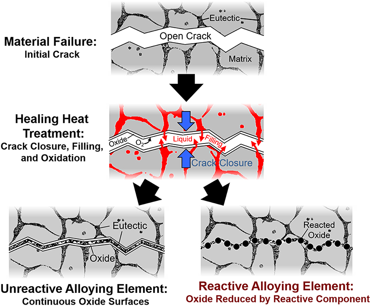
Figure 1. Schematic of crack healing in alloy systems with reactive vs. non-reactive element additions. An alloying element more reactive than the base metal will reduce oxides at the interface, thus creating a strong, thermodynamically-favorable bond.
The approach of using a more reactive element in a liquid phase has been used in joining technologies such as liquid phase sintering (LPS) (Kingery, 1959; German et al., 2009) and transient liquid phase bonding (TLP) (Gale and Butts, 2004; Cook and Sorensen, 2011). Additionally, investigations into lead-free solders with rare-earth element additions to increase bond strength between metals and oxides have yielded positive results (Mavoori et al., 2002; Wu, 2004; Dong et al., 2008). The improvement in bond strength is attributed to a strong chemical bond created at the solid/liquid interface through reduction of the metal oxide by the rare-earth element addition, which possess a highly negative free energy of formation (Mavoori et al., 2002; Ramirez et al., 2002; Wu and Wong, 2006). Thus, the increase in interface strength is not the result of oxide prevention, but of a reduction of the surface oxide enabling chemical bonding at the interface.
With the goal of incorporating these technologies into a self-healing metallic system, this study seeks to prove this phenomenon in a model system to ensure scientific rigor before shifting the technique to structural self-healing systems. Two similar alloys are investigated, one with an alloying element more reactive than the base metal and one with an alloying element less reactive. A Chevron Notched Short Bar Sample (CNSB) sample geometry enables quantification of the strength of bonded and monolithic material (Mecholsky and Barker, 1984; O'Dowd et al., 1992). Additionally, analysis using metallography and fractography techniques will be used connect thermodynamic parameters to mechanical properties.
Experimental
Alloy Design
To evaluate the difference in the bonding behavior between a reactive and non-reactive element in a healing cycle, two binary alloy systems of the same base metal were selected which displayed the following three characteristics: (1) each system exhibited a low temperature eutectic phase transformation with similar eutectic temperatures and compositions, (2) each system had limited solubility of the reactive or non-reactive species (i.e., translating to the additive element strongly partitioning to the liquid phase during heat treatment), and (3) one binary should possess an alloying element with a higher free energy of oxide formation than the base element, while the other binary should possess an alloying element with a lower free energy of oxide formation than the base element. These criteria ensured that the alloys are microstructurally and mechanically similar, with variable alloying element reactivity.
After a thorough search of thermodynamic data and phase diagrams, antimony-copper (Sb-Cu) and antimony-zinc (Sb-Zn) were chosen as the model system to test the reactive element hypothesis as shown in Figure 2. For this study, Sb serves as the base element, while Cu is the thermodynamically less reactive and Zn is the more reactive addition based on the Gibbs energy change for the respective reaction as shown in Figure 3A.
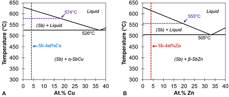
Figure 2. Partial binary phase diagrams for (A) Sb-Cu and (B) Sb-Zn highlighting the high Sb region. Note the similarities between the two eutectic reactions. Adapted from ASM (2012).
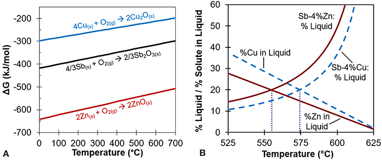
Figure 3. (A) Ellingham diagram of oxides showing Cu, Sb, and Zn. Note how oxide formation of ZnO would preferentially occur over Sb2O3, but not Cu2O over Sb2O3. Adapted from Reed (1971). (B) Percent liquid and percent solute in liquid at different temperatures for Sb-4at% Zn and Sb-4at% Cu. The crossing point for each alloy yields the healing temperature, 555°C for Sb-4Zn and 574°C for Sb-4Cu, as also shown in Figure 2. Adapted from ASM (2012).
The 4at% alloying element composition was selected by plotting the percent liquid and percent solute in liquid vs. temperature for a wide range of compositions, as shown in Figure 3B (ASM, 2012). The 4at% composition ensured there would be sufficient alloying element in the liquid phase during heat treatment while still maintaining a robust heat treatment temperature. Using the results of Figure 3B, each alloy's heat treatment temperature was chosen to be that which yielded 20% liquid and 80% solid to minimize liquid continuity and thus ensure structural stability during the healing cycle (Manuel, 2007). The desired intersections translate to heat treatment temperatures of 555°C for Sb-Zn and 574°C for Sb-Cu as shown in Figure 3B, and labeled on the phase diagrams in Figure 2. Alloys of each eutectic composition, Sb-37at% Cu and Sb-33at% Zn, were also prepared for testing to quantify the strength of the solidified liquid phase for comparative purposes.
Figure 4 shows the free energies of reaction for the three possible reactions of Zn or Cu with Sb2O3 on a per-mole oxygen basis at the calculated heat treatment temperatures (Reed, 1971). The ΔG0 values, as opposed to those used for the Ellingham diagram in Figure 3A, are adjusted to account for activity of the reactants since the compounds are assumed to be not in their standard states. Reactions with negative free energy are favorable, while those with positive energy are unfavorable. Thus, Zn should reduce Sb2O3 (to Sb metal and ZnO) at the heat treatment temperature and Cu should not, confirming the basis for choosing the alloys as the model system. This confirms the results from the original Ellingham diagram comparison of the relative reactivity of Zn, Sb, and Cu.
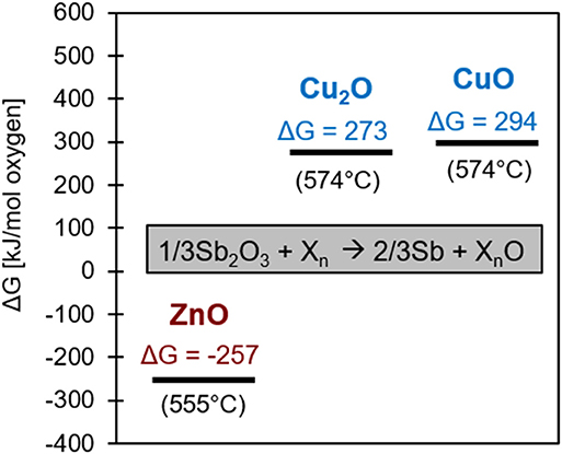
Figure 4. Free energy diagram of the three possible ways Zn or Cu can reduce Sb2O3. The adjustment of ΔG0, the reference free energy for each specific oxide of Cu or Zn, to ΔG considers thermodynamic activity for the 4 at% alloys at the healing temperature.
Experimental Procedure
A methodology based on interfacial plane-strain fracture toughness testing via the chevron-notch short bar (CNSB) technique (Chizhi et al., 1984; Mecholsky and Barker, 1984; Newman, 1984) was used to evaluate bonding effectiveness for each of the bonded and monolithic specimens. Fatigue pre-cracking was not necessary due to the brittle nature of the interface causing a sharp crack to be initiated at the tip of the chevron-shaped notch. A schematic of a representative CNSB specimen is found in Figure 5A. This geometry of the CNSB specimen fabricated a B/W ratio of 1.45 and an a0/W ratio of 0.4.
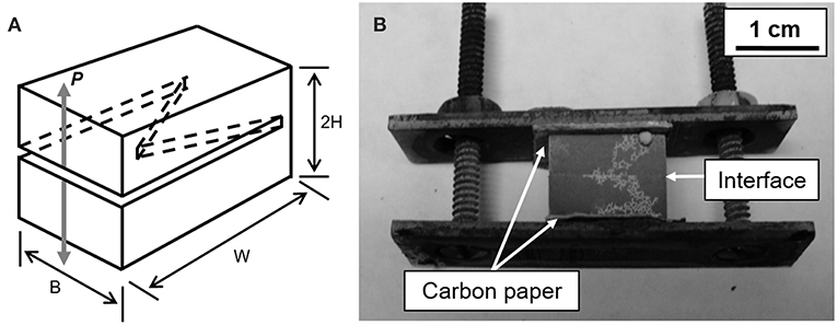
Figure 5. (A) Schematic of chevron notch short bar specimen (CNSB). Adapted from Newman (1984). (B) Representative image of a Sb-4Zn bonded specimen showing the configuration after heat treatment.
The alloys were prepared by placing appropriate amounts of antimony (99.999% shot, Alfa Aesar) and copper (99.9% shot, Alfa Aesar) or zinc (99.99% shot, Alfa Aesar,) in boron nitride-coated graphite crucibles at 750°C until a liquid solution formed. Each alloy was cast into a coated graphite bar mold and allowed to air cool.
The eutectic composition alloys, Sb-37Cu and Sb-33Zn, were heat-treated at 400°C in air for 24 h to homogenize the as-cast microstructure before machining. The Sb-4Zn and Sb-4Cu alloys were heat-treated in air for 24 h at 555 and 574°C, respectively, to stabilize the microstructure and then subsequently air-cooled. All specimens were machined to a nominal size of 10 mm × 10 mm × 14 mm and ground to a 320-grit surface finish to reduce the possibility of surface cracks skewing results.
To evaluate bonding characteristics, a set of the Sb-4Zn and Sb-4Cu alloys were longitudinally cut in half and polished to a 4,000-grit finish on the cut surfaces. The polished surfaces of each half were pressed together and placed into a steel clamp covered with carbon paper to prevent any chemical reaction between the steel and the specimen during heat treatment as shown in Figure 5B. These specimens underwent the identical heat treatment as their monolithic counterparts (Sb-4Zn and Sb-4Cu alloys heat-treated in air for 24 h at 555 and 574°C, respectively) in order to compare bonded and monolithic specimens with the same microstructure as confirmed through optical microscopy.
After heat treatment, a chevron notch was machined into all Sb-Zn and Sb-Cu specimens as per ASTM Standard E-1304 (ASTM, 2008). For the bonded specimens, the notch was located along the bonded interface. During testing, it was found that a portion of the bonded samples did not have full connectivity in the chevron notch region, making the test inappropriate for true K1c testing. However, the test is still useful for determining how well samples bonded and comparing to unbonded monolithic samples, thus maximum load during the test is used for comparison purposes. CNSB samples were tested on a TerraTek Model 4400A Fractometer. After testing, the specimens were also examined using optical microscopy (OM), scanning electron microscopy (SEM), and energy dispersive spectroscopy (EDS).
Results
The experimental data from the fracture toughness testing, in terms of maximum load, is summarized in Table 1. For each specimen type the average with one standard deviation values are shown. Comparing the bonded samples to each other, the difference in normalized maximum bond strength is statistically significant to p < 0.005. The maximum load of the bonded specimens, normalized to the monolithic of their sample type, is shown in the bar chart in Figure 6.
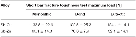
Table 1. Fracture toughness values of Sb-Cu and Sb-Zn chevron-notch short bar specimens.
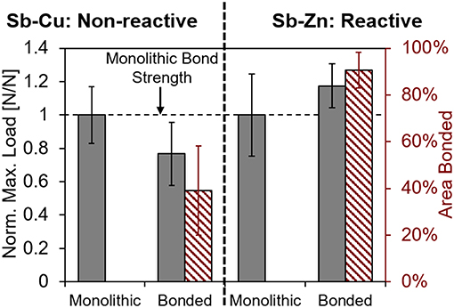
Figure 6. Results of chevron notch testing showing maximum load of bonded Sb-Cu and Sb-Zn normalized to their respective monolithic maximum loads.
Representative images of the fracture surfaces for both Sb-4Cu and Sb-4Zn bonded alloys are shown in Figure 7. The dashed lines show the location of the chevron notch, whereas the solid line represents the end of the bonded area over which the fracture occurred. For the Sb-4Cu alloys, the remaining, non-bonded, area is coated in a layer of Sb2O3 (as confirmed through EDS analysis) from the oxidation of Sb during heat treatment. It was noted that the Sb-Zn specimens bonded over a larger area than Sb-Cu specimens, as shown on the right axis of the chart in Figure 6.
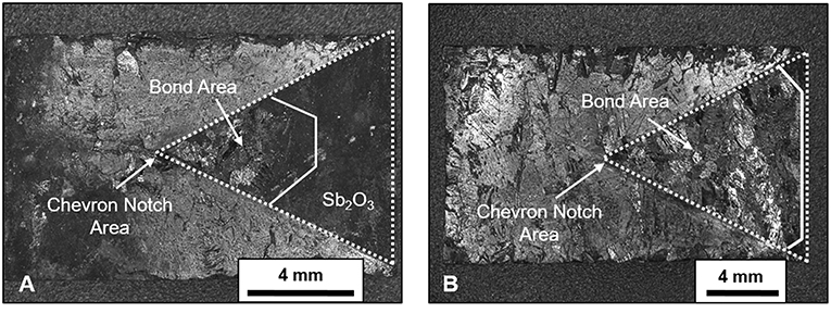
Figure 7. Images of (A) Sb-Cu and (B) Sb-Zn showing top view the chevron notch fracture surface after bonding heat treatment and subsequent fracture toughness testing. The dashed lines show the entire area of the chevron notch, whereas the solid white line shows the end of the bond, and hence fracture, area.
Representative micrographs of Sb-4Cu and Sb-4Zn in Figure 8 show that all alloys exhibit coarse microstructures; on average, the Sb-4Cu grains were approximately 500 μm and Sb-4Zn grains were approximately 700 μm. The coarseness of the microstructure likely contributes to the spread in bonding strength. The phases present at the grain boundaries of all the Sb-4Cu and Sb-4Zn monolithic and bond specimens was determined to be eutectic in nature based on the dual-phase morphology. As seen in Figure 8, the eutectic phases can be observed near the interface in both the Sb-Cu and Sb-Zn bond specimens. EDS analysis also revealed the presence of Zn and O at the bond interface, likely in the form of ZnO. Copper oxide was not found along the Sb-Cu bonded interface; instead, a Sb2O3 phase was found on the outer perimeter of the specimens.
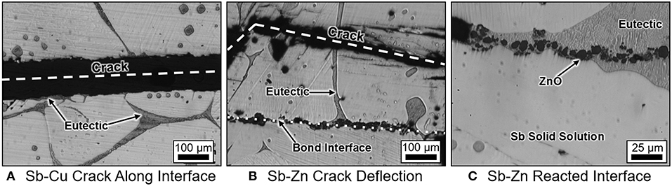
Figure 8. Representative micrographs of (A) Sb-4at% Cu and (B) Sb-4at% Zn showing fracture line after bonding. Note that the Sb-Zn alloys had fractures occur away from the bonded interface. (C) Image of the Sb-4at% Zn bonded microstructure highlighting ZnO along the bond interface formed by the reduction of Sb2O3 by Zn.
Discussion
The behavior of bonded alloys Sb-4Cu and Sb-4Zn in the chevron notch testing is different in three important ways. First, during healing, the bond area reliably bonded to a much greater degree in the Sb-Zn samples as highlighted by the chart in Figure 6 and the representative images in Figure 7. Second, the bonded Sb-Zn samples became stronger than their monolithic counterparts, whereas the bonded Sb-Cu samples became weaker after healing than their monolithic counterparts as shown by the chart in Figure 6. Finally, the crack propagation pathway through the specimen was distinct between the alloy types. For Sb-4Cu, the crack in the bonded specimens moved along the bond line, whereas for Sb-4Zn, the strong bond along the interface causes crack deflection away from the bonded interface and along the grain boundaries as shown in Figure 8C. A detailed description of the thermodynamic driving force to explain the crack deflection in Sb-4Zn follows. These interconnected effects are attributed to the thermodynamic driving force for oxide formation in the liquid phase during the bonding heat treatment.
Thermodynamic Driving Force
During the bonding heat treatment for the Sb-4Zn and Sb-4Cu alloys, the eutectic constituents (Sb + β-SbZn or Sb + η-SbCu) and a portion of primary Sb liquefied as the temperature was raised above the eutectic temperature. The main half-reactions of Sb, Zn and Cu with O2 at the processing temperatures are shown in Table 2. Since Sb is known to oxidize readily at elevated temperatures, especially above 500°C (Russell and Lee, 2005), the newly liquefied eutectic phases in the Sb-Cu and Sb-Zn alloys would immediately begin to form Sb2O3 on the exposed surfaces, including the cut and polished interface in accordance with the Sb + O2 half reaction shown in Table 2.
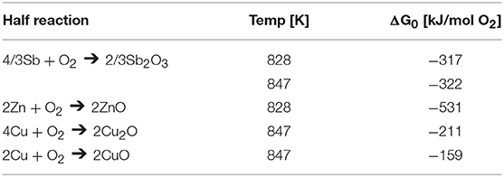
Table 2. Thermodynamic half-reactions of Sb, Zn, and Cu at relevant heat treatment temperatures.
Figure 5B shows the small spheres of excess Sb2O3 formed on the outside of each specimen. These features were found on all of the bonded specimens after heat treatment. The presence of this surface oxide was noted on every Sb alloy and verified through EDS analysis.
To analyze the propensity for each reaction to occur, activities of each component in the reaction were considered by the following method. For Equation (1) below, in which two reactants (i and j) react to form two products (k and l), w, x, y and z are the coefficients. For this reaction, the free energy of formation can be calculated by Equation (2), in which ΔG0 is the standard free energy of formation at temperature T, R is the gas constant, and aw to az are the activities of each reaction component raised to their coefficients. Given this relationship and the relevant half-reactions, the free energies Zn(l) and Cu(l) reacting with Sb2O3 to form their oxides are calculated in Table 3. Activities of Zn and Cu with Sb are provided from literature (Li et al., 2007; Gierlotka and Jendrzejczyk-Handzlik, 2009). Activities for the oxides are assumed to be 1.
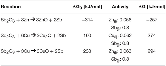
Table 3. Free energies for the reaction of Sb2O3 with Zn and Cu at 555 and 574°C, respectively, according to Equation (2).
Bonding Behavior
The ability to bond the separated halves of material was found to be dependent on the ability of the alloying element to reduce Sb2O3 at the interface. At the heat treatment temperatures (555°C for Sb-4Zn and 574°C for Sb-4Cu), the alloys have a liquid phase with 20at% solute available to react with oxygen. As seen in Table 3, Zn(l) is expected to react with Sb2O3 to form ZnO, as the reaction has a significantly negative free energy (Reed, 1971). However, since both Cu2O and CuO possesses a greater Gibbs free energy of formation than Sb2O3, it is not thermodynamically favorable for Cu to reduce the Sb2O3 formed along the interface during heat treatment, as indicated by the positive free energy of formation.
This formation of ZnO creates a chemical bond, essentially welding the two halves of the specimen together during the heat treatment. Additionally, Zn reduces the Sb2O3 that normally would not melt at 555°C and thus inhibit bonding. Although it was anticipated that the Sb-4Zn alloys would display an increase in interfacial fracture toughness over the monolithic value due to its increased propensity of forming a strong bond the interface, it was noted that the bonded samples did not deviate significantly from monolithic. Close inspection of the crack path in Figure 8B shows that the crack progressed through the bulk of the specimen as opposed to the strongly bonded interface. The low fracture toughness of the bulk facilitated this failure mechanism as it represented the “weakest link.” It was also noted that often the crack path followed the eutectic constituent network, which was the least fracture resistant component of the system. The crack had to follow a more tortuous path not along the main bond line, possibly accounting for the slightly elevated maximum load.
There was also no physical evidence of Cu2O bonding the halves together as there was ZnO in the Sb-4Zn alloys. The Sb2O3 in Sb-Cu bonded specimen passivated the crack surface, thereby preventing efficient bonding by the liquefied eutectic constituent. Figure 7 shows the reduction of bonded surface area at the interface, which is quantified in Figure 6. It is suspected that the Sb2O3 would start forming at the exterior edges of the interface first and continue inward to the center of the specimen. Therefore, the bonded area of the interface would have only been in the center of each specimen where the Sb2O3 was not able to form. As the chevron notch was cut after the heat-treatment was completed, the bonded area was near the tip of the chevron notch, locating the crack front at the center of the specimen. This unexpected processing condition would explain why the fracture area for the Sb-Cu alloys was at the interior of each of the chevron notch specimens. The reduction in bond area could account for the lowered maximum load shown in Figure 6.
Another possible explanation for differences in bond area is a change in wettability. This phenomenon would correlate with previous studies in which a reactive element increased liquid metal wettability on metal oxide (Humenik and Kingery, 1954; Naidich, 1981; Peden et al., 1991; Finnis, 1996). This increase in wettability and bonding was also similar to results found by several groups working on lead-free solders (Mavoori et al., 2002; Ramirez et al., 2002; Wu and Wong, 2006; Dong et al., 2008). These groups have shown that small additions of rare-earth elements to lead-free solders enables interfacial bonding to several classes of materials including steels, oxides and carbides.
Conclusion
This paper illustrates how a reactive element alloying addition possessing a lower free energy of oxide formation than the base element can improve self-healing capability in a metallic system. Results from a model system showed an improvement in bonded area across a bonded interface, compared to non-reactive control, as well as crack deflection away from the healed crack. The improved bonding was attributed to the formation of stable oxides formed at the interface through the reduction of the passivate parent metal surface oxide, resulting in a strong chemical bond across the interface.
The results from the model Sb-Cu/Zn system show promise for using the reactive element technique within self-healing in structural metallic systems, especially for healing in an oxygen-containing environment. Additionally, this work could benefit powder additive manufacturing of metals, in which oxygen incorporation reduces toughness dramatically. However, there is a need for further investigation to better understand the effect of solute and liquid volume fractions on the process, as only 4% solute, 20% liquid, and 24 h heat treatment schedules were investigated. Additionally, this methodology must be demonstrated in more industrially relevant systems like Al and Mg with the addition of reactive alloying elements to find industrial application.
Author Contributions
CF performed the majority of the material testing and manuscript writing. JM assisted with test program design and manuscript revision. HH and MK assisted with manuscript revisions and figure development. MM served as advisor to CF, HH, and MK in addition to project design and manuscript revision.
Conflict of Interest Statement
The authors declare that the research was conducted in the absence of any commercial or financial relationships that could be construed as a potential conflict of interest.
Acknowledgments
The authors would like to gratefully acknowledge the support of the NASA Space Technology Research Opportunities for Early Career Faculty under grant number NNX12AQ42G and the Department of Defense and the Office of the Navy for their financial support through the Science, Mathematics, and Research for Transformation (SMART) Scholarship, a part of the National Defense Education Program.
References
ASTM (2008). “Standard E 1304 - 97 (Reapproved 2008),” in Standard Test Method for Plane-Strain (Chevron-Notch) Fracture Toughness of Metallic Materials, eds. H. Okamoto, M. E. Schlesinger, and E. M. Mueller (West Conshohocken, PA: ASTM International), 585–590.
Chizhi, W., Maochan, Y., and Tzeguang, C. (1984). “An investigation on the method for determination of fracture toughness KIc of metallic materials with chevron-notched short-rod and short-bar specimens,” in Chevron-Notched Specimens: Testing and Stress Analysis, ASTM STP 855, eds. J. H. Underwood, S. W. Freiman., and F. I. Baratta (Philidelphia, PA: American Society for Testing and Materials), 193–204. doi: 10.1520/STP32730S
Cook, G. O., and Sorensen, C. D. (2011). Overview of transient liquid phase and partial transient liquid phase bonding. J. Mater. Sci. 46, 5305−5323. doi: 10.1007/s10853-011-5561-1
Dong, W., Shi, Y., Xia, Z., Lei, Y., and Guo, F. (2008). Effects of trace amounts of rare earth additions on microstructure and properties of Sn-Bi-based solder alloy. J. Electron. Mater. 37, 982–991. doi: 10.1007/s11664-008-0458-8
Finnis, M. W. (1996). The theory of metal-ceramic interfaces. J. Phy. Condensed Matter 8, 5811–5836. doi: 10.1088/0953-8984/8/32/003
Fisher, C. R., Henderson, H. B., Kesler, M. S., Zhu, P., Bean, G. E., Wright, M. C., et al. (2018). Repairing large cracks and reversing fatigue damage in structural metals. Appl. Mater. Today 13, 64–68. doi: 10.1016/j.apmt.2018.07.003
Gale, W. F., and Butts, D. A. (2004). Transient liquid phase bonding. Sci. Technol. Weld. Join. 9, 283–300. doi: 10.1179/136217104225021724
German, R. M., Suri, P., and Park, S. J. (2009). Review: liquid phase sintering. J. Mater. Sci. 44, 1–39. doi: 10.1007/s10853-008-3008-0
Ghosh, S. K. (2009). Self-Healing Materials: Fundamentals, Design Strategies, and Applications. Hoboken, NJ: Wiley-VCH. doi: 10.1002/9783527625376
Gierlotka, W., and Jendrzejczyk-Handzlik, D. (2009). Thermodynamic description of the Cu–Sb binary system. J. Alloys Comp. 484, 172–176. doi: 10.1016/j.jallcom.2009.05.056
Hager, M. D., Greil, P., Leyens, C., Zwaag, S. V. D., and Schubert, U. S. (2010). Self-healing materials. Adv. Mater. 22, 5424–5430. doi: 10.1002/adma.201003036
Humenik, J. M., and Kingery, W. D. (1954). Metal-ceramic interactions: III, surface tension and wettability of metal-ceramic systems. J. Am. Ceram. Soc. 37, 18–23. doi: 10.1111/j.1151-2916.1954.tb13972.x
Kingery, W. D. (1959). Densification during sintering in the presence of a liquid phase - 1. theory. J. Appl. Phy. 30:301 doi: 10.1063/1.1735155
Li, J.-B., Record, M.-C., and Tedenac, J.-C. (2007). A thermodynamic assessment of the Sb–Zn system. J. Alloys Comp. 438, 171–177. doi: 10.1016/j.jallcom.2006.08.035
Manuel, M. V. (2007). Design of a biomimetic self-healing alloy composite (Ph.D), Evanston, IL: Northwestern University.
Mavoori, H., Ramirez, A. G., and Jin, S. (2002). Lead-free universal solders for optical and electronic devices. J. Electron. Mater. 31, 1160–1165 doi: 10.1007/s11664-002-0005-y
Mecholsky, J. J., and Barker, L. M. (1984). “A chevron-notched specimen for fracture toughness measurements of ceramic-metal interfaces,” in Chevron-Notched Specimens: Testing and Stress Analysis, ASTM STP 855, eds. J. H. Underwood, S. W. Freiman & F. I. Baratta (Philadelphia: American Society for Testing and Materials), 324–336. doi: 10.1520/STP32738S
Naidich, J. V. (1981). The wettability of solids by liquid metals. progress in surface and membrane science. Prog. Surf. Membr. Sci. 14, 353–484. doi: 10.1016/B978-0-12-571814-1.50011-7
Newman, J. C. Jr. (1984). “A review of chevron-notched fracture specimens,” in Chevron-Notched Specimens: Testing and Stress Analysis, ASTM STP 855, eds. J. H. Underwood, S. W. Freiman and F. I. Baratta. (Philadelphia: American Society for Testing and Materials), 5–31. doi: 10.1520/STP32719S
O'Dowd, N. P., Stout, M. G., and Shih, C. F. (1992). Fracture toughness of alumina-niobium interfaces: experiments and analyses. Philos. Mag. A 66, 1037–1064. doi: 10.1080/01418619208248005
Peden, C. H. F., Kidd, K. B., and Shinn, N. D. (1991). Metal/metal-oxide interfaces: a surface science approach to the study of adhesion. J. Vacuum Sci. Technol. A 9:1518. doi: 10.1116/1.577656
Ramirez, A. G., Mavoori, H., and Jin, S. (2002). Bonding nature of rare-earth containing lead-free solders. Appl. Phy. Lett. 80, 398–400. doi: 10.1063/1.1435075
Reed, T. B. (1971). Free Energy of Formation of Binary Compounds: An Atlas of Charts for High Temperature Chemical Calculations. Cambridge, MA: MIT Press. doi: 10.1149/1.2404111
Russell, A. M., and Lee, K. L. (2005). Structure-Property Relations in Nonferrous Metals. Hoboken, NJ: John Wiley and Sons, Inc. doi: 10.1002/0471708542
White, S. R., Sottos, N. R., Geubelle, P. H., Moore, J. S., Kessler, M. R.S., Viswanathan, R., et al. (2001). Automatic healing of polymer composites. Nature 409, 794–797. doi: 10.1038/35057232
Wu, C. (2004). Properties of lead-free solder alloys with rare earth element additions. Mater. Sci. Eng. R Rep. 44, 1–44. doi: 10.1016/j.mser.2004.01.001
Wu, C. M. L., and Wong, Y. W. (2006). Rare-earth additions to lead-free electronic solders. J. Mater. Sci. Mater. Electron. 18, 77–91. doi: 10.1007/s10854-006-9022-6
Wu, D. Y., Meure, S., and Solomon, D. (2008). Self-healing polymeric materials: a review of recent developments. Prog. Poly. Sci. 33, 479–522. doi: 10.1016/j.progpolymsci.2008.02.001
Keywords: interfacial bonding, thermodynamic, chevron notch, liquid phase, self-healing
Citation: Fisher CR, Mecholsky JJ Jr, Henderson HB, Kesler MS and Manuel MV (2019) A Reactive Element Approach to Improve Fracture Healing in Metallic Systems. Front. Mater. 6:210. doi: 10.3389/fmats.2019.00210
Received: 22 November 2018; Accepted: 14 August 2019;
Published: 29 August 2019.
Edited by:
John L. Provis, University of Sheffield, United KingdomReviewed by:
Amit Bandyopadhyay, Washington State University, United StatesAmy Sarah Gandy, University of Sheffield, United Kingdom
Copyright © 2019 Fisher, Mecholsky, Henderson, Kesler and Manuel. This is an open-access article distributed under the terms of the Creative Commons Attribution License (CC BY). The use, distribution or reproduction in other forums is permitted, provided the original author(s) and the copyright owner(s) are credited and that the original publication in this journal is cited, in accordance with accepted academic practice. No use, distribution or reproduction is permitted which does not comply with these terms.
*Correspondence: Michele V. Manuel, bW1hbnVlbEBtc2UudWZsLmVkdQ==