 Christian Riekel
 Manfred Burghammer
- The European Synchrotron Radiation Facility (ESRF), Grenoble, France
This report focuses on current possibilities and perspectives of scanning X-ray nanodiffraction for probing nanoscale heterogeneities in silk fibers such as nanofibrils, skin-core morphologies, nanocrystalline inclusions and fine fibers down to submicron diameters.
Introduction
Progress in mimicking biological silk production and designing advanced functional materials relies on understanding silks hierarchical organization and its relation to macroscopic function. While mechanics trends across the spider phylogeny for major ampullate silks (MaS) can be deduced from protein sequence (Blackledge et al., 2012), detailed modeling of specific mechanical properties requires information on silks functional elements and their hierarchical organization. Here we will consider functional elements up to the nanoscale, which are accessible to X-ray scattering techniques. Indeed, β-sheet nanodomains of several nm size, embedded in an amorphous matrix of protein chains, are basic functional elements of MaS fibers observed by wide-angle X-ray scattering (WAXS) (Fraser and MacRae, 1973). This two-phase model is used in various molecular modeling approaches based on phenomenological or molecular dynamics approaches for simulating protein chain behavior in the amorphous phase (Termonia, 1994; Papadopoulos et al., 2009; Su and Buehler, 2016; Puglisi et al., 2017). Morphological features such as protein chain self-assembly into nanofibrils (see below) can be simulated by assuming nanodomains interconnected by pre-strained chains (Papadopoulos et al., 2009). Lamellar distributions of nanodomains are also obtained from bottom-up molecular dynamics simulations (Cetinkaya et al., 2011). Interestingly a skin-core morphology is assumed for balancing prestressed chains in the core, experimentally observed by infrared spectroscopy (Papadopoulos et al., 2009).
The experimental observation of nanofibrils relies principally on scattering (e.g., X-ray and neutron small-angle scattering, SAXS/SANS) and imaging (e.g., transmission electron microscopy, TEM, and others) techniques. SAXS/SANS data provide shape information but have to be transformed into real space assuming usually cylindrical objects (Yang et al., 1997; Sapede et al., 2005). For highly crystalline bagworm silk several levels of nanofibrillar assembly have been revealed (Yoshioka et al., 2019). The local distribution and interactions of nanoscale functional elements including skin-core morphologies cannot, however, be obtained from such studies which are usually performed on fiber bundles. X-ray microbeam diffraction (microXRD) allows probing single, μm-sized silk fibers (Riekel and Vollrath, 2001), paving the way for studying silks available only in small quantities (Craig, 2003), but has a limited reciprocal space (SAXS) resolution (see also conclusions) and cannot resolve skin-core morphologies. In contrast, high resolution imaging techniques such as transmission electron microscopy (TEM) and atomic force microscopy (AFM) allow local imaging of nanoscale functional elements from single nanofibrils to skin-core morphologies but only for very thin samples, which may require embedding, sectioning and staining. Indeed, a skin-core morphology has been revealed by TEM for Nephila's MaS fibers (Frische et al., 1998) and single recluse spider nanofibrils of 20 × 7 nm2 cross-section have been imaged by AFM (Wang and Schniepp, 2018). Arguably there is, however, insufficient knowhow on dimensional aspects, volume density and spatial distribution of nanofibrils and other nanoscale functional elements in silk fibers, limiting the development of mechanical models (Wang and Schniepp, 2019).
Here we will discuss the scope of scanning X-ray nanodiffraction (nanoXRD) combining bulk sensitivity with nanoscale lateral resolution. Specifically, we will provide an update on Argiope's MaS skin-core morphology (Riekel et al., 2017) and extend it to B. mori's cocoon silk. Radiation damage issues will be discussed for the smallest focal spots used. We will show for the case of Argiope's stabilimentum that scanning nanoXRD allows probing down to subμm diameter silk fibers and provide an outlook on R&D opportunities enabled by the ongoing upgrade of the ESRF source brightness.
Methods
NanoXRD experiments were performed at the ID13 undulator beamline at The European Synchrotron (ESRF: www.esrf.eu) (Riekel et al., 2017). Monochromatic focal spots of 170–180 nm fwhm (full-width-half-maximum) with a flux density of ~1.5*105 photons/s/nm2 were generated by refractive lenses (Riekel et al., 2017) and of 40–50 nm fwhm with a flux density of ~1.3*107 photons/s/nm2 by multilayer Laue lenses (Kubec et al., 2017). X-ray transparent Si3N4 membranes provide stable sample supports (Figures 1C–E) (Riekel et al., 2017). Local structural information is obtained by step-scanning samples through the focal spot and recording diffraction patterns in transmission geometry at each position by a single photon counting pixel detector (Dectris®) at a calibrated distance (Figures 1A,B). Typical exposure times used were 2 s for the ~180 nm and 0.1 s for the ~40 nm focal spots. The sequence of patterns obtained in a mesh-scan (Figures 1A,B) is transformed into a composite diffraction image (called here: “composite image”) corresponding to a real space projection of local reciprocal space variations. Selecting the angular range of pixels extending into the wide-angle scattering (WAXS) or small-angle X-ray scattering (SAXS) range allows visualizing atomic-scale or morphological-scale features (Riekel et al., 2009, 2017).
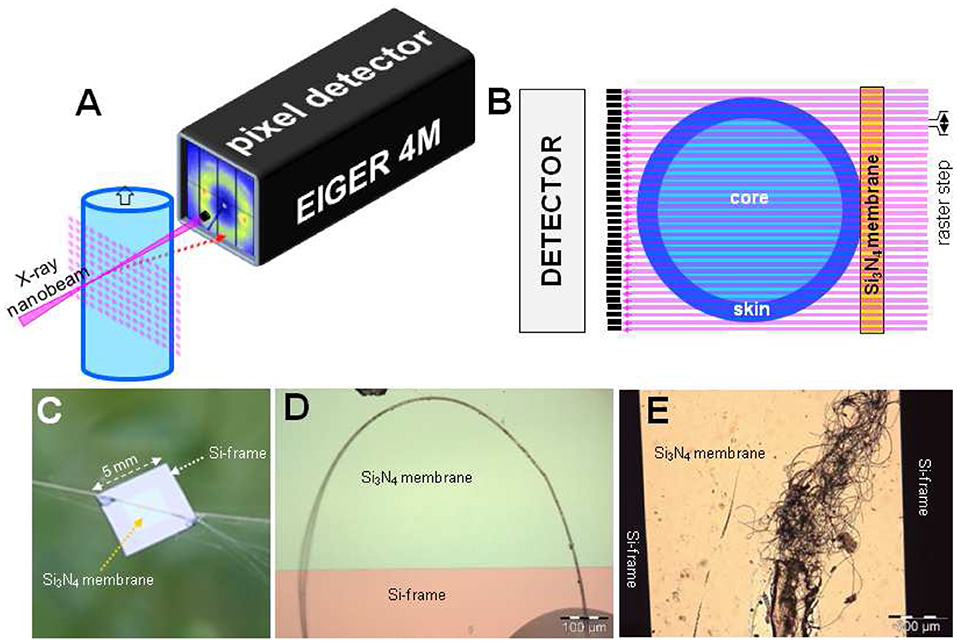
Figure 1. Methodological aspects of scanning nanoXRD. (A) Mesh-scan of fiber through X-ray focal spot. Diffraction patterns are recorded at each step. (B) View normal to beam direction of mesh-scan through fiber section with skin-core morphology. The depth-of-focus guarantees a quasi-constant spot diameter across the fiber. (C) A. bruennichi's bridge-thread bundle glued to Si3N4 membrane supported by a Si-frame; (D) Bridge-thread bent into a loop for probing local deformation (not reported below). (E) Decorating fibers from A. bruennichi's stabilimentum. (B,C) Reproduced/adapted from Riekel et al. (2017) with permission from ACS.
Applications
NanoXRD Patterns
NanoXRD patterns for Argiope bruennichi's MaS bridge-thread with the ~180 nm focus (Riekel et al., 2017) and an untreated Bombyx mori's cocoon bave with the ~40 nm focus are shown in Figures 2A–D. The fiber texture (observed also for single patterns) is due to a preferential axial alignment of the polypeptide chains in the <5 nm size nanodomains. Indeed, for ~180 nm focus at the center of a 5 μm diameter B. mori fiber of ~50% crystallinity ~108 unit cells contribute to the Bragg peaks and ~5*106 unit cells for a 40 nm focus, decreasing by factor 20 for a 100 nm thick layer at the rim. The equatorial WAXS profiles agree to those obtained by X-ray microdiffraction (microXRD) (Riekel et al., 1999; Martel et al., 2007; Figures 2E,F), holding also for derived crystallographic parameters (e.g., peak position, particle size) (Riekel et al., 2017). The beam divergence of the ~180 nm focus allows resolving the MaS ~10 nm SAXS correlation peak from the beamstop (inset Figure 2B) (Riekel et al., 2017). A broadened correlation peaks is just visible for the ~40 nm focus at the edge of the beamstop (Figure 2C; red arrow). The geometry (e.g., beamstop size, sample-detector distance) was, however, not optimized for SAXS.
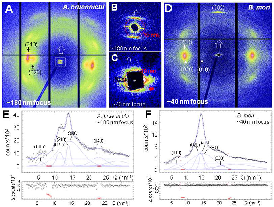
Figure 2. NanoXRD patterns of silk fibers. 20 patterns were averaged for the ~180 nm focus and 201 patterns for the ~40 nm focus. (A) A. bruennichi's MaS fiber pattern for 190 nmhor × 170ver nm2 (fwhm) focus. Black vertical and horizontal lines correspond to inactive detector areas. (B) SAXS-range for ~180 nm focus. Open arrow along (meridional) fiber axis. (C) SAXS-range for ~40 nm focus; red arrow points to correlation peak at the edge of the beamstop. (D) B. mori's pattern for 50hor × 35ver nm2 (fwhm) focus. (E,F) Equatorial intensity profiles (black crosses) and fitted curves by Gaussians for Bragg/SRO peaks; 0-order polynomial for random background (Q = 2π/d; d: lattice spacing); individual Gaussians shown after subtraction of polynomial. Lower plots: differences of observed minus simulated profiles. Inactive detector areas (in red) masked for the fits. Millers indices correspond to poly(L-alanine) or poly(L-alanylglycine) lattices (Marsh et al., 1955a,b). The forbidden (100)* reflection is discussed in Riekel et al. (2017).
MaS Fibers
Biochemical and spectroscopic studies suggest a skin-core morphology with two proteneous and a very thin lipidic coat surrounding the core (Sponner et al., 2007). Scanning nanoXRD suggests that the inner proteneous coat is amorphous, consisting of nanofibrillar bundles (Riekel et al., 2017). Indeed, the WAXS composite image appears to be homogeneous (Figures 3A,B). This holds also for the SAXS composite image based on the meridional correlation peak, attributed to the nanodomains stacks making up the nanofibrils (Figures 3C,D). A skin-layer is, however, revealed in the SAXS composite image based on the equatorial streak (Figures 3E,F). The modulated intensity profile of one of the streaks (inset Figure 3G) can be modeled by scattering from cylindrical rods (Figure 3G). Streaks from different locations within the skin suggest a variability in rod diameters from about 40–140 nm (Figure 3H) which was also observed by AFM for nanofibrils from the skin-layer of B. mori and wild silk fibers (Putthanarat et al., 2000).
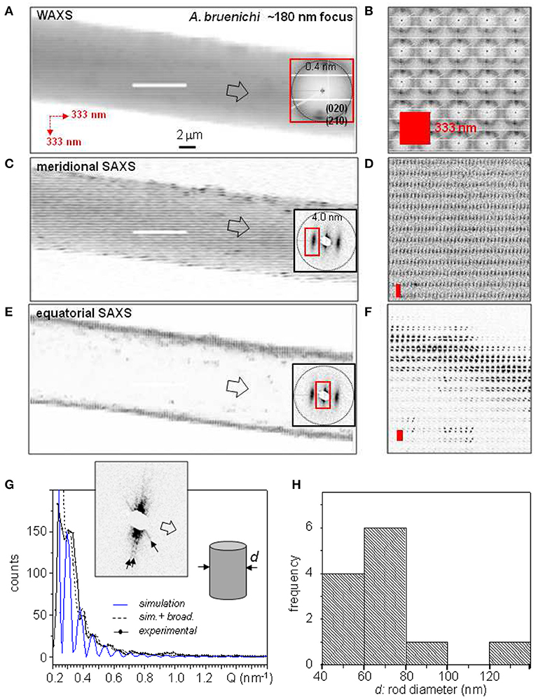
Figure 3. Composite images of A. bruennichi's bridge-thread based on 333 nmhor × 333 nmver raster-steps through 170 nmhor × 170 nmver (fwhm) focus. The insets show patterns from the center of the fiber. (A) Based on strongest WAXS peaks and SRO scattering. (C) Based on meridional SAXS correlation peak. (E) Based on equatorial SAXS streak. (B,D,F) Zooms of composite images to the left; red rectangles correspond to step-increments. (G) Simulation of scattering from nanofibrils in the skin-layer by cylindrical model. (H) Histogram of skin-layer cylinder diameters. Reproduced/adapted from Riekel et al. (2017) with permission from ACS.
The smallest rod diameters for the MaS thread are observed for positions close to the inner interface of the skin-layer. Individual streaks from nanofibrils observed at this location support the suggestion of a less densely packed layer at the inner interface of the skin-layer (Frische et al., 1998). The local nanofibrillar orientation agrees to the model of a nanofibrillar layer wound around the core (Vollrath et al., 1996).
Evidence for a fragile glycoprotein skin-layer covering the protein coat (Sponner et al., 2007) has not been clearly established as only amorphous patches covered by a thin lipidic layer -possibly due to a degraded glycoprotein coat- were observed (Riekel et al., 2017). A partially peeled-off layer provides, however evidence for a further skin-layer (Figure 4A). Indeed, the WAXS composite image reveals powder-like scattering (Figure 4B). Averaged patterns show two textured powder rings from Bragg peaks with d = 0.415 (±0.001) nm, d = 0.375 (±0.003) nm lattice spacings which do not correspond to β-sheet peaks (Figures 4C,D). Additional SRO scattering supports the model of a thin disordered proteneous layer decorated by nanocrystalline inclusions. The Bragg peaks can be related to clusters of nanocrystals of about 40 nm size derived from their peak-width using Scherrer's equation (Klug and Alexander, 1974). The peak positions and calculated intensities agree to hexagonal polyglycine II (PG-II) (Crick and Rich, 1955) with a = b = 0.481 (±0.001) nm, c = 0.960 (±0.003) nm. We note that a skin-layer decorated by ~3.5 nm PG-II nanocrystallites has also been observed by scanning nanoXRD for thin flag silk fibers (Riekel et al., 2019). Although the topic will not be discussed in this article, PG-II reflections can provide an alternative explanation for the S,S* peaks and their intensity ratio observed in MaS fibers (Riekel et al., 1999, 2017; Trancik et al., 2006), which were discussed previously only in the context of the non-periodic lattice (NPL) model (Thiel et al., 1994, 1997).
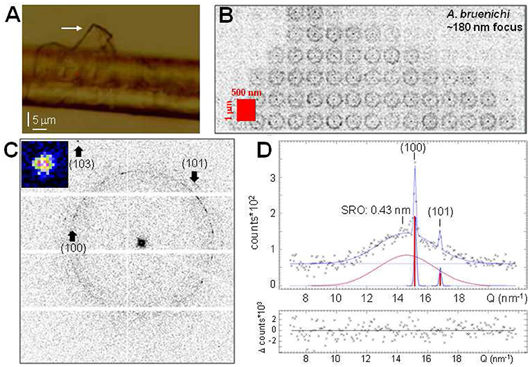
Figure 4. Polyglycine-II (PG-II) nanocrystallites in MaS skin-layer. (A) Optical microscopy of thin layer (white arrow) detaching from A. bruennichi's MaS thread's surface. (B) WAXS composite image based on 500 nmhor × 1 μmver raster-steps (red rectangle) from the tip of the layer in (A) through a 190hor × 170ver nm2 (fwhm) focus. The pixels are 16× binned to enhance weak scattering. (C) Average of patterns from the composite image; positions of (100)/(101) PG-II reflections indicated. A (103) peak with d = 0.254 nm (zoom) is indicated at the edge. The limited amount of higher order PG-II reflections is due to the preferred [001] texture, reducing the probability of Bragg scattering. (D) Radial intensity profile of (C). Gaussians fitted to Bragg peaks (dotted-blue) and SRO scattering (dotted-red); 0-order polynomial fitted to random background. The calculated intensities of the PG-II (100)/(101) Bragg peaks (Crick and Rich, 1955) are indicated as red bars, scaled to the height of the (100) Gaussian.
Silkworm Fibers
Composite images from a B. mori bave were obtained for the ~40 nm focus. WAXS composite images based on the equatorial (210/020) and meridional (002) reflections show a homogeneous matrix as for the MaS thread (Figures 5A–D). The weak SAXS streaks are oriented normal to the fiber axis implying axially oriented nanofibrils. A slight intensity increase of the streaks is only observed at the rim (Figures 5E,F). Three nanofibrillar fractions of ±48°/0° with respect to the fiber axis in a supposedly layered morphology were deduced from AFM images of peeled, degummed B. mori fibers and correlated with WAXS data (Putthanarat et al., 2000). We tested this model by averaging all patterns in every horizontal scan-line to increase counting statistics, resulting in a pseudo line-scan normal to the bave axis. A continuous intensity increase of the (020)/(210) Bragg peak from the interface is observed as the fiber volume probed by the focal spot increases while the SAXS streak intensity shows an anomalous increase for 3–4 patterns near the interface (Figure 5G). The azimuthal intensity profile at the (020) position can best be simulated by an overlap of two Gaussians with different width (Figure 5H). Three Gaussians simulating three nanofibrillar fractions splitting the peak (Putthanarat et al., 2000) do, however, not fit the profile. The narrow peak is attributed to scattering from nanodomains while the broader peak -extending outside the Bragg peaks along the equator- is probably due to a more ordered SRO fraction overlapping the SRO powder ring. We determined the nanodomains orientation function as fc~0.93 from the (002) reflections azimuthal width of 12.76° fwhm, corresponding to A. bruennichi's MaS fc-value (Riekel et al., 2017). A ribbon-like nanofibrillar layer wound around the core would imply a variation of the streaks orientations (e.g., Figure 3G) which is not observed for B. mori. The anomalous intensity of the streaks near the interface could be due to an increase in scattering density contrast due to sericin penetrating the outer fibroin layers (Mueller and Hentschel, 2004), analog to water penetrating MaS fibers (Riekel and Vollrath, 2001). In summary, there is no evidence for a significant fraction of nanofibrils differing from a unique axial orientation distribution. While it cannot be excluded that the three fractions differing in orientation deduced by AFM (Putthanarat et al., 2000) are related to the degumming process, caution is necessary when correlating surface sensitive AFM with bulk sensitive XRD results.
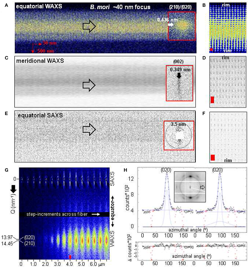
Figure 5. Composite images of B. mori bave based on 50 nmhor × 500 nmver raster-steps through a 50 nmhor × 35 nmver focus. Note that the two fibers are nearly overlapping in projection. Insets: patterns from the center of the bave. (A) Based on (210)/(020) Bragg peaks. (C) Based on the (002) Bragg peak. (E) Based on the equatorial SAXS streak. Open arrows along fiber axis. (B,D,F) Zooms of composite images to the left (distorted for better viewing). Red rectangles correspond to step-increments. (G) Pseudo line-scan across part of the bave covering the equatorial SAXS streak and the (020)/(210) peaks. The upper part of the streak is partially extinguished due to a scattering artifact (image expanded vertically by about factor 5). (H) Fit of azimuthal profile through (020) peak (inset) for pattern indicated by red arrow in (G) by Gaussian and 0-order polynomial functions. Fit by single Gaussian to the left; fit by two Gaussians with different width to the right. Inactive detector areas (in red) masked for the fits.
X-Ray Radiation Damage
X-ray radiation damage due to radicals generated from residual water molecules affects the crystallinity of unexposed neighboring scan-points in a scanning nanoXRD experiment (Riekel et al., 2017). This loss in order increases as the step-width is reduced and affects particularly experiments with the smallest focal spots. We determined radiation damage effects for a ~50 nm focal spot by performing consecutive line-scans normal to A. bruennichi's MaS fiber axis at 1 μm distance for 500, 250, 100, and 50 nm step-increments (Figure 6A).
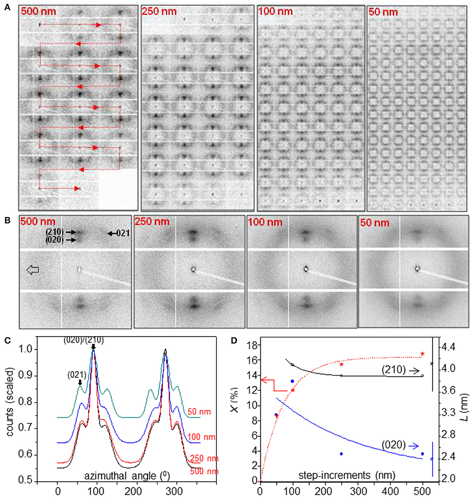
Figure 6. Radiation damage effects during line-scans of A. bruennichi's MaS fiber through a ~50 nm focus. (A) Linear scans normal to fiber axis for step-increments indicated as red insets; 1 s exposure per pattern. The red line for 500 nm step-increments indicates the succession of patterns in a line-scan across the fiber. (B) Averaged patterns for each line-scan. (C) Radially integrated averaged patterns up to the 1st layer-line scaled to the maximum intensity of the (210) reflections (=1.0). (D) Variation of crystallinity (X; red stars) and particle size (L) for (020) (blue circles) and (210) (black circles) peaks as a function of step-increments. Exponential functions fitted as guides-to-the eye, assuming X = 0% for 0 nm focal spot size. L-values with 2σ error bars to the right were obtained for a 170 nm focus (Riekel et al., 2017).
The patterns were averaged for each line-scan and integrated radially (Figures 6B,C). An increase in SRO with reduction of Bragg peak intensities is observed for 100/50 nm step-increments. This is also reflected in the variation of the crystallinity (X) and is accompanied by a reduction of the radial peak width of the equatorial reflections corresponding to a particle size (L) increase (Figure 6D). L-values for 250/500 nm step-increments correspond within errors to those obtained for a 170 nm focus (Riekel et al., 2017). As the L-values correspond to an average over all crystalline nanodomain sizes we assume that a preferential destruction of the smaller nanodomains explains the shift to larger L-values with increasing radiation damage. This conclusion was also derived from mesh scans through a 170 nm focus suggesting that the step increment has to be in the order of ≥500 nm to minimize radiation damage effects for current scanning nanoXRD conditions (Riekel et al., 2017). For qualitative work a certain extent of radiation damage can be accepted when reducing step-increments. To reduce radiation damage effects, mesh-scans are often performed as successive line-scans with as small as possible step-increment while the separation of neighboring scan-lines is increased to ≥500 nm (Figures 5A–F). Radiation damage effects are generally less important for higher crystalline B. mori fibers allowing line-scans with down to 50 nm step-increments.
Fine Silk Fibers
Fine silk fibers down to subμm diameters are becoming accessible to scanning nanoXRD as shown for decorating fibers composing the stabilimentum of Argiope spiders (Figure 7A) which are attributed to aciniform silk (Herberstein et al., 2000; Foelix, 2011). Indeed, composite images reveal the contours of the fibers (Figures 7B,D,E). The WAXS pattern is dominated by diffuse scattering from a disordered fraction with additional weak intensity modulations resembling MaS SRO scattering (Figure 7C). A narrow equatorial peak at the MaS (210) position suggests a fraction of β-type nanodomains of about 5 nm particle size. The relatively strong peak at the position of the forbidden MaS (100) reflection (Riekel et al., 2017) could be due to side-group disorder of polypeptide chains. We estimate the volume fraction of the β-type material <5% from the ratio of the β-type scattering to the broad diffuse scattering background. The focal spot size is, however, too large for determining the local distribution of β-type scattering and verifying the possibility of a skin-core structure. The rim of the fibers is revealed by equatorial SAXS streaks (Figures 7D,E) with intensity modulations implying a nanofibrillar morphology (Figure 7F). Analysis of the intensity modulations for a rod-like objects (see Figure 3G) suggests a rod diameter of about 50 nm.
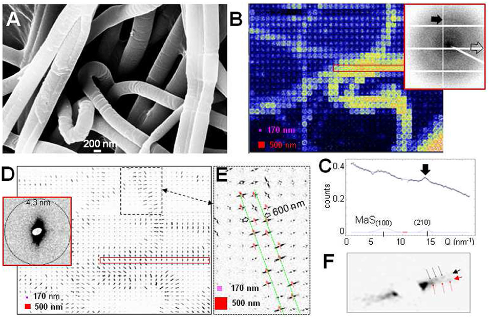
Figure 7. Scanning nanoXRD of A. bruennichi's decorating fibers with 500 nmhor × 500 nmver raster-steps through a 170 nmhor × 170 nmver focus. (A) Scanning electron microscopy (SEM) image of decorating fibers (Zeiss Leo SEM: 10 KV, 10 nm sputtered gold layer). (B) WAXS composite image covering diffuse powder ring in inset-pattern; pink square: focus size; red square: step-increments (also in D,E). Inset: averaged scattering from patterns within red, open rectangle. Black arrow indicates a weak equatorial peak; open arrow along local fiber axis. (C) Equatorial WAXS profile fitted by 2 Gaussians for Bragg peaks and a 1st-order polynomial for the overall diffuse scattering. Black arrow as for inset-pattern in (B). MaS(100)/(210) positions: (Riekel et al., 2017). (D) SAXS composite image based on equatorial streak. Inset shows averaged scattering from within red rectangle. (E) Zoom of dashed area in (D); SAXS streaks define the contours (in green) of an about 600 nm diameter fiber (or thread); red arrows: local fiber axes. (F) Zoom into streak at rim of the fiber in (E) revealing two intensity-modulated streaks with ~100 angular separation (black/red arrows).
Conclusions and Outlook
The skin-core morphology of MaS fibers has been investigated by scanning nanoXRD and the presence of two proteneous layers -suggested by biochemical and spectroscopic studies (Sponner et al., 2007)—has been confirmed. No evidence for skin-core morphology has, however, been obtained for a silkworm fiber. One of the MaS layers appears to be amorphous with nanofibrillar morphology. The other layer, which is probably formed by glycoproteins (Sponner et al., 2007), is decorated by PG-II nanocrystallites. This type of skin-layer covering an amorphous core has also been observed for A. marmoreus flagelliform silk (Riekel et al., 2019). We note that morphologies based on ordered skin-layers and a more disordered core, providing a balance of strength and toughness, are well-known for synthetic polymeric fibers (Müller et al., 2000; Liu et al., 2014). PG-II nanodomains have only recently been suggested as functional elements, reinforcing flagelliform silk fibers (Perea et al., 2013). S,S* reflections observed for MaS fibers are probably also based on PG-II nanodomains. Systematic studies of nanoscale heterogeneities across the spider phylogeny should shed light on the presence and local distribution of β-sheet, PG-II and possibly other nanocrystalline inclusions. Potential targets are β-type nanodomains in Argiope decorating fibers (Figure 7B), the probably ribbon-like morphology of Eriophora MiS fibers (Riekel et al., 2001) and PG-II nanodomains in several flagelliform silks probed by microXRD (Craig, 2003; Perea et al., 2013). Such studies could also contribute to an understanding of the nature of graphene and single-walled carbon nanotubes inclusions in spiders MaS and silkworm fibroin fibers (Wang et al., 2014, 2016; Lepore et al., 2017).
The ESRF is currently being upgraded in the context of the “Extremely Bright Source” (EBS) project from a 3rd to a 4th generation synchrotron radiation source with an expected increase in brightness by more than an order in magnitude (Dimper et al., 2015). This should allow scanning nanoXRD techniques evolving into providing enhanced reciprocal space (SAXS) resolution for focal spots down to around 100 nm or aim at very small focal spots in the 10–30 nm range with a limited SAXS resolution. Both types of focal spots will likely provide new insights into silks hierarchical organization and will also require exploring advanced sectioning approaches such as focused ion beam (FIB) techniques. Increasing the composite image spatial resolution (pixel-density) will require, however, new data collection approaches for reducing radiation damage, enabling also tomographic approaches. Indeed, cryocooling techniques adapted to the high positional sample stability requirements would allow blocking radical propagation. The aim of correlating microstructure with macroscopic (e.g., mechanical) properties will continue, however, requiring room temperature experiments. It will be interesting exploring whether more intense nanobeams would allow outrunning radical propagation into unexposed scan-points by faster scan-modes enabled by high readout-frequency pixel detectors. This could provide access to nanoscale resolution composite images of parts of orb-webs comprising functionally different fibers including junctions and of dynamic processes related to crystallization or aggregation.
Data Availability Statement
All datasets generated for this study are included in the article/supplementary material.
Author Contributions
All authors listed have made a substantial, direct and intellectual contribution to the work, and approved it for publication.
Conflict of Interest
The authors declare that the research was conducted in the absence of any commercial or financial relationships that could be construed as a potential conflict of interest.
Acknowledgments
We thank Dr. Irina Snigireva (ESRF microimaging lab) for providing the SEM image of decorating fibers.
References
Blackledge, T. A., Pérez-Rigueiro, J., Plaza, G. R., Perea, B., Navarro, A., Guinea, G. V., et al. (2012). Sequential origin in the high performance properties of orb spider dragline silk. Sci. Rep. 2:782. doi: 10.1038/srep00782
Cetinkaya, M., Xiao, S., Markert, B., Stacklies, W., and Gräter, F. (2011). Silk fiber mechanics from multiscale force distribution analysis. Biophys. J. 100, 1298–1305. doi: 10.1016/j.bpj.2010.12.3712
Craig, C. L. (2003). Spiderwebs and Silk: Tracing Evolution From Molecules to Genes to Phenotypes. New York, NY: Oxford University Press.
Crick, F. H., and Rich, A. (1955). Structure of polyglycine II. Nature 176, 780–781. doi: 10.1038/176780a0
Dimper, R., Reichert, H., Raimondi, P., Sánchez Ortiz, L., Sette, F., and Susini, J. (2015). Orange Book: ESRF Upgrade Programme Phase II (2015-2022)-Technical Design Study. Grenoble: ESRF; The European Synchrotron.
Fraser, R. D. B., and MacRae, T. P. (1973). Conformations of Fibrous Proteins. New York, NY: Academic Press.
Frische, S., Maunsbach, A., and Vollrath, F. (1998). Elongate cavities and skin-core structure in Nephila spider silk observed by electron microscopy. J. Microscopy 189, 64–70. doi: 10.1046/j.1365-2818.1998.00285.x
Herberstein, M. E., Craig, C. L., Coddington, J. A., and Elgar, M. A. (2000). The functional significance of silk decorations of orb-web spiders: a critical review of the empirical evidence. Biol. Rev. 75, 649–669. doi: 10.1111/j.1469-185X.2000.tb00056.x
Klug, H. P., and Alexander, L. E. (1974). X-ray Diffraction Procedures for Polycrystalline and Amorphous Materials. New York, NY: Wiley Interscience.
Kubec, A., Melzer, K., Gluch, J., Niese, S., Braun, S., Patommel, J., et al. (2017). Point focusing with flat and wedged crossed multilayer laue lenses. J. Synchotron Rad. 24, 413–421. doi: 10.1107/S1600577517001722
Lepore, E., Bosia, F., Bonaccorso, F., Bruna, M., Taioli, S., Garberoglio, G., et al. (2017). Spider silk reinforced by graphene or carbon nanotubes. 2D Mater. 4:031013. doi: 10.1088/2053-1583/aa7cd3
Liu, Q., Gao, H., Zha, L., Hu, Z., Ma, Y., Yu, M., et al. (2014). Tuning bio-inspired skin–core structure of nascent fiber via interplay of polymer phase transitions. Phys.Chem.Chem.Phys. 16, 15152–15157. doi: 10.1039/C4CP00792A
Marsh, R. E., Corey, R. B., and Pauling, L. (1955a). An investigation of the structure of silk fibroin. Biochim. Biophys. Acta 16, 1–34. doi: 10.1016/0006-3002(55)90178-5
Marsh, R. E., Corey, R. B., and Pauling, L. (1955b). The Structure of Tussah Silk Fibroin. Acta Cryst. 8, 710–715. doi: 10.1107/S0365110X5500217X
Martel, A., Burghammer, M., Davies, R. J., and Riekel, C. (2007). Thermal degradation of Bombyx mori silk: evolution of molecular dtructure, crystalline parameters and mechanical properties. Biomacromolecules 8, 3548–3556. doi: 10.1021/bm700935w
Mueller, B. R., and Hentschel, M. P. (2004). Synchrotron radiation refraction tomography for characterization of lightweight materials. X-ray Spectr. 33, 402–406. doi: 10.1002/xrs.736
Müller, M., Riekel, C., Vuong, R., and Chanzy, H. (2000). Skin/core micro-structure in viscose rayon fibres analysed by X-ray microbeam and electron diffraction mapping. Polymer 41, 2627–2632. doi: 10.1016/S0032-3861(99)00433-4
Papadopoulos, P., Soelter, J., and Kremer, F. (2009). Hierarchies in the structural organization of spider silk - a quantitative model. Colloid Polym. Sci. 287, 231–236. doi: 10.1007/s00396-008-1968-x
Perea, G. B., Riekel, C., Guinea, G. V., Madurga, R., Daza, R., Burghammer, M., et al. (2013). Identification and dynamics of polyglycine II nanocrystals in Argiope trifasciata flagelliform silk. Sci. Rep. 3:3061. doi: 10.1038/srep03061
Puglisi, G., De Tommasi, D., Pantano, M. F., Pugno, N. M., and Saccomandi, G. (2017). Micromechanical model for protein materials: from macromolecules to macroscopic fibers. Phys. Rev. E 96:042407. doi: 10.1103/PhysRevE.96.042407
Putthanarat, S., Stribeck, N., Fossey, S. A., Eby, R. K., and Adams, W. W. (2000). Investigation of the nanofibrils of silk fibers. Polymer 41, 7735–7747. doi: 10.1016/S0032-3861(00)00036-7
Riekel, C., Braenden, C., Craig, C., Ferrero, C., Heidelbach, F., and Müller, M. (1999). Aspects of X-ray diffraction on single spider fibers. Int. J. Biol. Macrom. 24, 179–186. doi: 10.1016/S0141-8130(98)00084-1
Riekel, C., Burghammer, M., Dane, T. J., Ferrero, C., and Rosenthal, M. (2017). Nanoscale structural features in spider bridge thread fibres. Biomacromolecules 18, 231–241. doi: 10.1021/acs.biomac.6b01537
Riekel, C., Burghammer, M., Davies, R., Gebhardt, R., and Popov, P. (2009). “Fundaments of soft condensed matter scattering and diffraction with microfocus techniques,” in Applications of Synchrotron Light to Scattering and Diffraction in Materials, Vol. 776, eds T. A. Ezquerra, M. Garcia-Gutierrez, A. Nogales, and M. Gomez. Heidelberg: Springer. 91–104. doi: 10.1007/978-3-540-95968-7_4
Riekel, C., Burghammer, M., and Rosenthal, M. (2019). Skin-core morphology in spider flagelliform silk. Appl. Phys. Lett. 115:123702. doi: 10.1063/1.5110268
Riekel, C., Craig, C. L., Burghammer, M., and Müller, M. (2001). Microstructural homogeneity of support silk spun by Eriophora fuliginea (C.L. Koch) determined by scanning X-ray microdiffraction. Naturwissenschaften 88, 67–72. doi: 10.1007/s001140000197
Riekel, C., and Vollrath, F. (2001). Spider silk fibre extrusion: combined wide- and small-angle X-ray microdiffraction experiments. Int. J. Biol. Macrom. 29, 203–210. doi: 10.1016/S0141-8130(01)00166-0
Sapede, D., Seydel, T., Forsyth, V. T., Koza, M., Schweins, R., Vollrath, F., et al. (2005). Nanofibrillar structure and molecular mobility in spider dragline silk. Macromolecules 38, 8447–8453. doi: 10.1021/ma0507995
Sponner, A., Vater, W., Monajembashi, S., Unger, E., Grosse, F., and Weisshart, K. (2007). Composition and hierarchical organisation of a spider silk. PLOS One 10:e998. doi: 10.1371/journal.pone.0000998
Su, I., and Buehler, M. J. (2016). Nanomechanics of silk: the fundamentals of a strong, tough and versatile material. Nanotechnolohy 27:302001. doi: 10.1088/0957-4484/27/30/302001
Termonia, Y. (1994). Molecular modelling of spider silk elasticity. Macromolecules 27, 7378–7381. doi: 10.1021/ma00103a018
Thiel, B. L., Guess, K. B., and Viney, C. (1997). Non-periodic lattice crystals in the hierarchical microstructure of spider (major ampullate) silk. Biopolymers 41, 703–719. doi: 10.1002/(SICI)1097-0282(199706)41:7<703::AID-BIP1>3.0.CO;2-T
Thiel, B. L., Kunkel, D., and Viney, C. (1994). Physical and chemical microstructure of spider dragline: a study by analytical transmission electron microscopy. Biopolymers 34, 1089–1097. doi: 10.1002/bip.360340812
Trancik, J. E., Czernuszka, J. T., Bell, F. I., and Viney, C. (2006). Nanostructural features of a spider dragline silk as revealed by electron and X-ray diffraction studies. Polymer 47, 5633–5642. doi: 10.1016/j.polymer.2005.01.110
Vollrath, F., Holtet, T., Thøgersen, H. C., and Frische, S. (1996). Structural organization of spider silk. Proc. R. Soc. Lond. B 263, 147–151. doi: 10.1098/rspb.1996.0023
Wang, J. T., Li, L. L., Zhang, M. Y., Liu, S. L., Jiang, L. H., and Shen, Q. (2014). Directly obtaining high strength silk fiber from silkworm by feeding carbon nanotubes. Mat Sci Eng C 34, 417–421. doi: 10.1016/j.msec.2013.09.041
Wang, Q., and Schniepp, H. C. (2018). Strength of recluse spider's silk originates from nanofibrils. ACS MacroLett. 7, 1364–1370. doi: 10.1021/acsmacrolett.8b00678
Wang, Q., and Schniepp, H. C. (2019). Nanofibrils as building blocks of silk fibers: critical review of the experimental evidence. JOM 71, 1248–1263. doi: 10.1007/s11837-019-03340-y
Wang, Q., Wang, C., Zhang, M., Jian, M., and Zhang, Y. (2016). Feeding single-walled carbon nanotubes or graphene to silkworms for reinforced silk fibers. Nano Lett. 16, 6695–6700. doi: 10.1021/acs.nanolett.6b03597
Yang, Z., Grubb, D. T., and Jelinski, L. W. (1997). Small-angle X-ray scattering of spider dragline silk. Macromolecules 30, 8254–8261. doi: 10.1021/ma970548z
Keywords: silk fibers, X-ray nanodiffraction, synchrotron radiation, skin-core structure, nanocrystallites, radiation damage
Citation: Riekel C, Burghammer M and Rosenthal M (2019) Nanoscale X-Ray Diffraction of Silk Fibers. Front. Mater. 6:315. doi: 10.3389/fmats.2019.00315
Received: 20 August 2019; Accepted: 20 November 2019;
Published: 04 December 2019.
Edited by:
Nicola Maria Pugno, University of Trento, ItalyReviewed by:
Domenico De Tommasi, Politecnico di Bari, ItalyDongchan Jang, Korea Advanced Institute of Science and Technology (KAIST), South Korea
Copyright © 2019 Riekel, Burghammer and Rosenthal. This is an open-access article distributed under the terms of the Creative Commons Attribution License (CC BY). The use, distribution or reproduction in other forums is permitted, provided the original author(s) and the copyright owner(s) are credited and that the original publication in this journal is cited, in accordance with accepted academic practice. No use, distribution or reproduction is permitted which does not comply with these terms.
*Correspondence: Christian Riekel, cmlla2VsQGVzcmYuZnI=