 Marco Rossi
 Daniele Veber1
 Massimiliano Gei
- 1Department of Civil, Environmental and Mechanical Engineering, University of Trento, Trento, Italy
- 2School of Engineering, Cardiff University, Cardiff, United Kingdom
A relevant application of transformation elastodynamics has shown that flexural waves in a Kirchhoff-Love plate can be diverted and channeled to cloak a region of the ambient space. To achieve the goal, an orthotropic meta-structural plate should be employed. However, the corresponding mathematical transformation leads to the presence of an unwanted strong compressive prestress, likely beyond the buckling threshold of the structure, with a set of in-plane body forces to warrant equilibrium. In addition, the plate must possess, at the same time, high bending stiffnesses, but a null twisting rigidity. With the aim of estimating the performance of cloaks modelled with approximate parameters, an in-house finite element code, based on a subparametric technique, is implemented to deal with the cloaking of transient waves in orthotropic thin plates. The tool allows us to explore the sensitivity of specific stiffness parameters that may be difficult to match in a real cloak design. In addition, the finite element code is extended to investigate a meta-plate interacting with a Winkler foundation, to confirm how the subgrade modulus should transform in the cloak region.
Introduction
State of the Art and Research Challenges
The control of elastic waves to cloak a region of the ambient space has been shown achievable by transformation elastodynamics, which provides the mechanical properties of the material surrounding the region (Milton et al., 2006; Brun et al., 2009; Norris and Shuvalov, 2011). A relevant application of this broad area is the control of transverse waves in plates, for which solutions have been proposed mainly based on two approaches: a “passive” one, where the features of the cloak are achieved by a given microstructure (Farhat et al., 2009a; Farhat et al., 2009b; Brun et al., 2014; Colquitt et al., 2014; Climente et al., 2016; Zareei and Alam, 2017; Liu and Zhu, 2019; Misseroni et al., 2019) and an “active” one, in which tunable quantities depending on the actual mechanical input are employed for the same goal (see e.g., Futhazar et al., 2015; O’Neill et al., 2015; Chen et al., 2016; Ning et al., 2020). Experiments have been also proposed to validate some of the previous theoretical proposals (Stenger et al., 2012; Misseroni et al., 2016; Darabi et al., 2018; Misseroni et al., 2019). Most of these investigations show that this technique can be feasible and likely to be employed in centimetre-size real-life systems with wave frequencies in the order of a few kHz.
Within the set of attempts based on the “passive” approach, Colquitt et al. (2014) proposed a transformation to conceive a Kirchhoff-Love plate theory for cloaking flexural waves. The resulting governing equations for the thin plate in the transformed domain involve the presence of variable (in space) bending and torsional stiffnesses, and density, in addition to the presence of in-plane body forces and prestresses in the plate. In the same paper, the general framework was specialised to the case of a square cloak composed of four trapezoidal elements (see Figure 1) embedded in an isotropic, homogeneous domain. For this geometry, a set of relationships was established to provide explicit expressions of the quantities concerned in each part of the cloak. The broadband effectiveness of the meta-material plate cloak was then assessed by means of numerical tests.
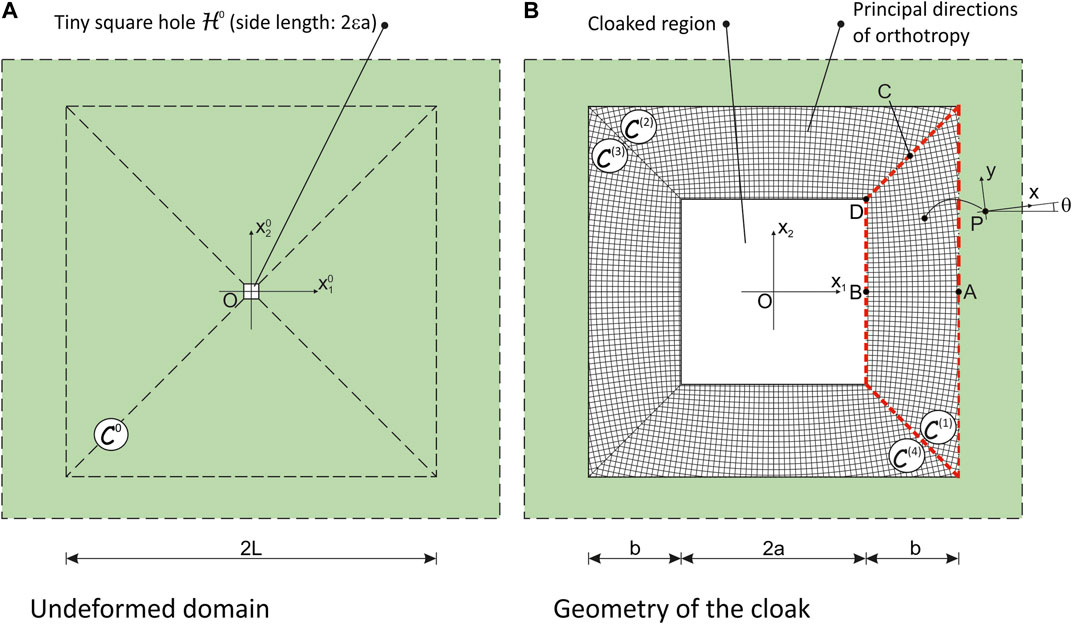
FIGURE 1. Sketch of a square meta-structural cloak studied by Colquitt et al. (2014): (A) initial, undeformed domain
The features of the suggested meta-structure can be summarised as follows:
(1) the cloak is locally an orthotropic thin plate with principal directions varying point-to-point. These directions obey the geometric symmetries of the domain (see, e.g., trapezoid displayed in Figure 1B, where the principal directions are sketched with thin lines). In the same figure, the increase of the out-of-alignment of the local principal system with the axis of symmetry towards the diagonals of the cloak can be noticed;
(2) by investigating how the stiffnesses of the plate in the orthotropic principal system depend on the position and thinking to construct the plate with a homogeneous material, it turns out that the thickness of the plate must assure an increase in bending stiffness along the direction parallel to the inner boundary of the cloak moving away the axis of symmetry of each trapezoid and a decrease of the bending stiffness along the “radial” direction moving towards the centre of the cloak. These two requirements are apparently in contradiction, but they must be addressed in an effective design;
(3) the twisting stiffness in the principal system of orthotropy vanishes at each point of the domain;
(4) the mass density of the cloak is not constant and varies with the Jacobian of the transformation; in particular, this quantity decreases by approaching the inner boundary of the cloak;
(5) in-plane body forces and prestresses in the interior of the domain as well as forces per unit length applied along the diagonals of the cloak are necessary to warrant equilibrium. The predicted prestress is compressive in a large part of the domain with values that are likely to exceed the buckling threshold for the thin structure.
The set of listed properties demonstrates that the design and engineering of an effective cloak for flexural waves based on transformation elastodynamics of Kirchhoff-Love plates is an exceptional challenge. Actually, the presence of severe compressive prestresses leads to the conclusion that it is impossible to construct a stable, ideal cloak. Therefore, an approach based on carefully considered approximations are required to achieve the goal. In the experimental test conducted by Misseroni et al. (2016), for instance, the design of the approximated cloak has focused mainly on the match of bending stiffnesses along the directions of orthotropy.
Moving from the points raised in the just edited list, the goal of the paper is four-fold:
(1) the first aim is to design and implement a fully open in-house FE code, based on a subparametric technique, to simulate transient wave propagation in locally orthotropic Kirchhoff-Love plates;
(2) the numerical tool is then exploited to assess the performance of meta-structural square cloaks designed by assuming reasonable approximations (prestress free, local twisting stiffness as limited as possible, cross sections of the plate ensuring the required local bending stiffnesses, non-constant mass density);
(3) the same tool is employed to investigate the role of certain stiffness parameters, i.e., twisting and coupling bending stiffnesses;
(4) in addition, a non-secondary purpose of the paper is to propose an extension of the theory to encompass interaction of the cloak with an elastic substrate modelled with a Winkler foundation and assess its effectiveness.
Background
The definition of the flexural cloak is based on a transformation, say
In both configurations, the exterior domain
where
The function
are instrumental in defining the properties of the cloak as shown by Colquitt et al. (2014).
In order to have a complete overview on the established theory of meta-plate cloaks, we remind that the local governing equation of a Kirchhoff-Love plate takes the form (Timoshenko and Woinowsky-Krieger, 1959; Lekhnitskii et al., 1968)
where σ is the mass density per unit area,
The next step is to substitute the constitutive equations that connect
an equation used by Colquitt et al. (2014) to identify the different terms corresponding to the transformation and confirm that the flexural displacement of a Kirchhoff-Love plate under an arbitrary coordinate mapping may be interpreted as a generalised plate.
The identification of terms shows that the stiffness tensor of the transformed plate corresponds to
the in-plane body forces to
and the transformed density per unit area turns out to be
When the Winkler foundation is involved, the subgrade coefficient transforms similarly to the density, i.e.,
a quantity that is now dependent on the position.
Focusing now on the square cloak transformation sketched in Figure 1 and, in particular, on trapezoid
and
and
For the same trapezoid
where
In the new local system
where the new stiffness moduli contained therein are provided in terms of
Interestingly, as shown by Colquitt et al. (2014), the twisting stiffness
The cloak is subjected to traction-free boundary conditions in the inner free boundary and to continuity conditions at the interface between itself and the outer homogeneous plate.
Numerical Model and Implementation in a In-House Finite Element Code
With the aim of performing numerical simulations via the Finite Element Method (FEM) of the transient dynamic behaviour of a square cloak, a weak form of the governing equations is now obtained. The formulation can be derived by multiplying Eq. 4 by the test function
where the term involving
Geometric and analytical approximations are performed to achieve the discretised formulation by dividing the entire domain into a finite subset of elements, i.e.,
respectively, where
where
A parametric representation is implemented in the code: the shape functions are defined in the local coordinate system
The structured mesh employed in the numerical analyses is composed of quadrangular elements with four nodes in the corner of each element whose generalised displacements are
leading to (
Finally, after substitution and integration of the aforementioned shape functions in Eq. 1 and the assembly operation over all the Finite Elements of the mesh, the set of algebraic equations used for the spatial approximation of this problem can be written as
where
The approximation in the time domain is performed with the single-step time-integration algorithm Generalized-α method (Chung and Hulbert, 1993; Chung and Hulbert, 1994) which is an evolution of the well-known Newmark method that is frequently used for transient dynamical analysis in mechanics (see Imbert, 1979; Hughes, 1987; Petyt, 1990; Zienkiewicz and Taylor, 2005). According to this method, Eq. 15 is written as
where a generic damping matrix
is performed with respect to the time-domain
The Taylor’s expansions of the solution
where
where
where
The Generalized-α method is completely described by the four parameters
It is worth mentioning that Eq. 15 can be profitably employed to perform time-harmonic simulations once a harmonic form for
The mass matrix can generally be computed in different ways: the consistent mass matrix
We implemented this numerical model in a Finite Element code, written using the software Matlab. The program deals with anisotropic and inhomogeneous thin elastic plates with different possible shapes of the domain and various kind of boundary and loading conditions. Using this code, it is also possible to perform static and modal analyses.
Numerical Simulations and Performance of the Cloak
Using the code described above, we studied the transient propagation of flexural waves in a simply-supported square plate in which a square hole is cloaked with respect to out-of-plane vibration generated by a point force varying sinusoidally. With reference to Figure 2, the homogeneous plate in
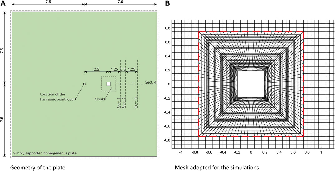
FIGURE 2. A) Geometry of the studied plate where it is visible the point where the time-varying force is enforced (dimensions in m) and the sections considered in Figure 4; (B) detail of the mesh, the external boundary of the cloak is marked with a dashed red line.
The boundary conditions on the outer perimeter are those of a simply supported plate, namely null transversal displacement
The mesh that we used for the transient analysis is composed of (
We performed a transient dynamical analysis with the Generalized-α method (see above) for which we chose
The performance of the cloak is now assessed with reference to the following case studies:
(1) a cloak possessing all properties of the Theoretical Transformation Without Prestress (TTWP) is analysed first. As recalled in the Introduction, the prestress is ruled out as it is not realistic to assume the distribution of initial stress
(2) a cloak possessing all properties of the TTWP–but with a different amount of torsional stiffness
(3) same as 2), but with the goal of estimating the role of the coupling bending stiffness
(4) a cloak with the properties predicted by the TTWP is then studied, but resting on a substrate modelled as a Winkler foundation whose position-dependent subgrade modulus obeys relationship Eq. 7.
For all case studies, the displacement maps and the other relevant quantities that are illustrated are computed at a time t compatible with a propagation of the wavefront located downline of the region of the cloak, but not significantly disturbed by secondary waves reflected at the boundary of the plate.
Performance of the Cloak
The displacement map of a TTWP cloak computed at
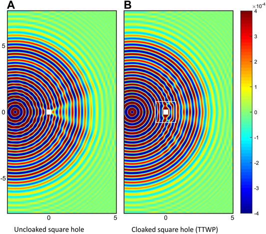
FIGURE 3. Displacement map w (in m) computed numerically at
In order to appraise more in detail the quality of the cloaking, Figure 4 reports the out-of-plane displacement w for the four sections sketched in Figure 2; the first three sections are transverse with respect to the propagation of the wave, at a distance from the centre of the hole of 1.25 m (Section no. 1), 1.75 m (Section no. 2) and 3 m (Section no. 3); the fourth one runs longitudinally from a point at 0.25 m just outside the right-hand boundary of the cloak to the external side of the plate. In all plots, the red line, which describes the displacements of the TTWP cloak, follows quite well the dashed line representing the response of the square, hole-less, homogeneous plate
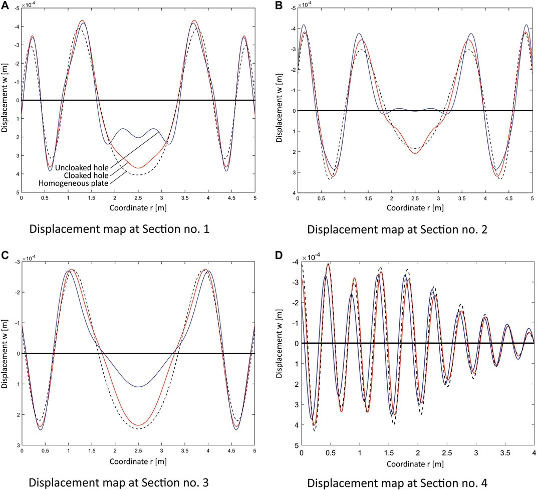
FIGURE 4. Displacement map w (in m) computed at
In order to measure quantitatively the quality of the cloak we adopt the index (Colquitt et al., 2014)
that is computed along the relevant section ς that is described by the co-ordinate r. Perfection corresponds to
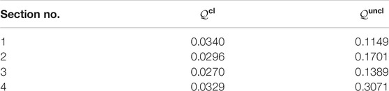
TABLE 1. Quality index for the four sections reported in Figure 4.
The effect of an amount of twisting stiffness on the displacement map of a cloak TTWP is displayed in Figure 5 where several increasing values of the parameter
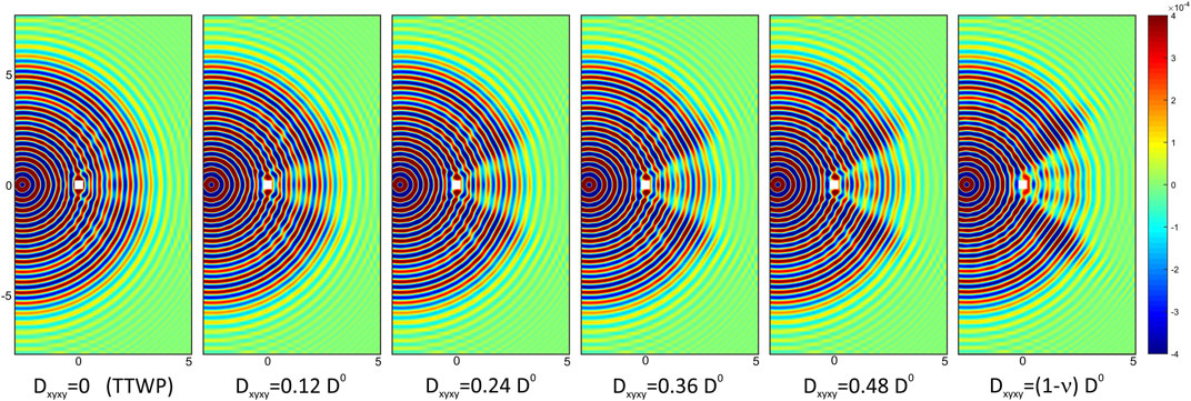
FIGURE 5. Displacement map w (in m) computed numerically at
A similar analysis can be reiterated for the coupling stiffness
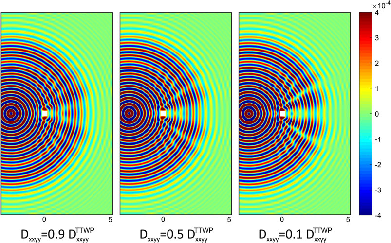
FIGURE 6. Displacement map w (in m) computed numerically at
The last picture of this subsection (Figure 7) refers to a TTWP cloak subjected to point-loads pulsating at different ω, to show that the approximate model is behaving well for a quite broad range of frequencies. The time of computation t differs from one picture to the other in order to compare a similar displacement pattern. For all displayed cases, the meta-plate is able to reconstruct satisfactorily the circular wavefront.
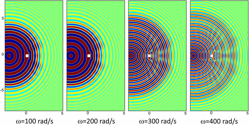
FIGURE 7. Displacement maps w (in m) computed numerically at frequencies 100, 200, 300 and 400 rad/s (at different times t in order to compare a similar displacement pattern) for a TTWP cloak.
Flexural Cloaks on Winkler Substrates
In real applications, cloaks are likely grounded to a substrate which also provides the support of the object to hide. The cloaking features of a plate resting on a Winkler foundation is analysed in Figure 8 for
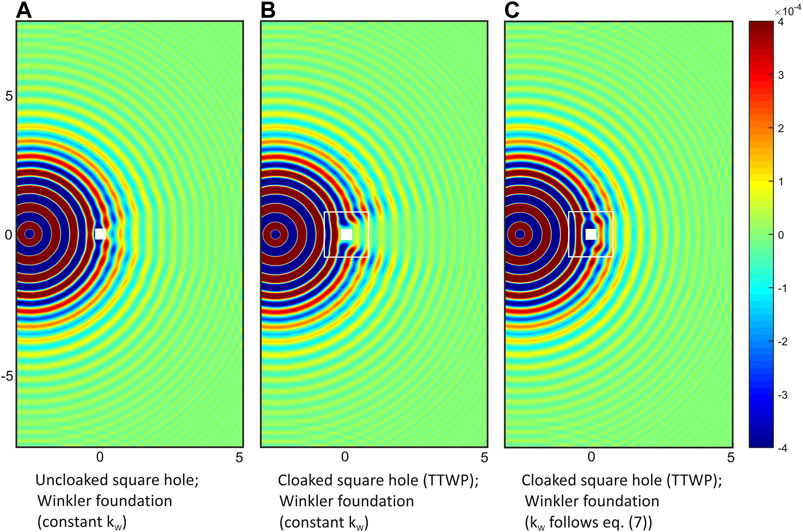
FIGURE 8. Displacement maps w (in m) computed numerically at
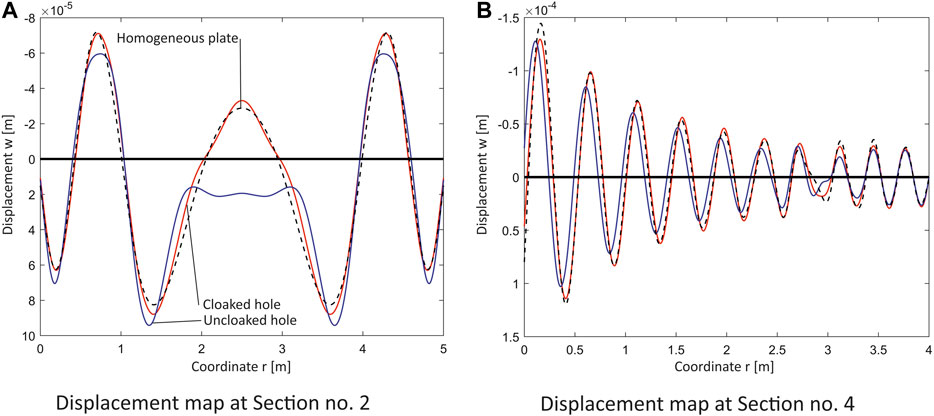
FIGURE 9. Displacement map w (in m) computed at
As a final remark of this section, one must note that the employed geometrical, elastic and loading conditions correspond to a chosen prototype geometry, but the scale of the dimensions, and the load intensity and frequency can be changed to obtain an identical behaviour on a different scaled structure subjected to different load conditions.
Concluding Remarks
The engineering of a meta-structural cloak for elastic flexural waves based on transformation elastodynamics is an exceptional challenge which theoretically would require the implementation of unfeasible compressive prestresses and in-plane body forces to warrant equilibrium. Therefore, reasonable assumptions should be adopted that are however grounded on the following main points: 1) the meta-plate has a locally orthotropic response with 2) an almost vanishing twisting stiffness, 3) spatially-varying bending stiffnesses and 4) density. In addition, the structure invariably would interact with a substrate.
With the aim of dealing with a fully open simulation tool, a FE code is developed and implemented with the specific purpose of studying transient wave propagation in locally orthotropic Kirchhoff-Love plates. A subparametric technique is adopted for spatial discretization, whereas the approximation in the time domain is performed with the single-step time-integration algorithm Generalized-α method.
The performance of a prototype meta-plate square cloak based on the approximate assumption of null prestress is then assessed parametrically by focusing specially on the role of the twisting stiffness and the coupling bending stiffness. The reason is that while the local principal bending rigidities can be matched quite easily in a microstructured plate, for those two parameters the process is much more difficult.
The simulations show that for an effective cloaking response, the twisting stiffness should be lower than 10
A second contribution of this work consists in the extension of the general theory of thin-plate cloaks to comprise interaction of the meta-structure with an elastic substrate via Winkler-foundation model. The conclusion is that the subgrade modulus transforms similarly to the mass density of the plate. The numerical simulations confirm this finding and clearly show that a constant modulus beneath the cloak jeopardizes dramatically the functionality of the structure.
The FE tool can be further expanded to embed inelastic responses of plate and substrate, thus enabling simulations of approximate supported meta-plates subjected to transient waves arising from seismic shocks.
Data Availability Statement
The raw data supporting the conclusions of this article will be made available by the authors, without undue reservation
Author Contributions
DV and MG conceived the idea. MR and DV developed and implemented the numerical tool. MR performed the simulations. MR, DV, and MG wrote the paper.
Conflict of Interest
The authors declare that the research was conducted in the absence of any commercial or financial relationships that could be construed as a potential conflict of interest.
Acknowledgments
MR acknowledges Italian Ministry of Education, University and Research (MIUR) for supporting their research under grant PRIN no. 2015LYYXA8. MG acknowledges support from EU-H2020-Marie Curie-Sklodowska Action-COFUND grant SIRCIW (agreement no. 663830).
Appendix A: Material Parameters and Pre-Stress for the Cloak
The six independent flexural stiffnesses for trapezoid
The remaining components can be deduced from the major and minor symmetries of
Stiffnesses transform locally as follows:
Appendix B: An Example of a Micro-Structured Plate Cloak
A design based on a micro-structured meta-plate is here proposed with the aim of matching locally the principal bending stiffnesses
In the spirit of the Kirchhoff-Love theory for plates, the core material is subjected to a plane-stress state, therefore the linear elastic constitutive equations read
whereas the teeth undergo a uniaxial stress (i.e.,
The effective stiffnesses
can be calculated by applying the standard methodology of integrating locally stresses across the plate thickness. The integration leads to
where
With reference to the square transformation displayed in Figure 1B, the properties of the two cross sections of the micro-structured plate can be defined as follows:
1) the function
2) Equation 25 can now be employed to compute
3) the teeth density
Eventually, the coupling term
The outcome of the design is shown in Tables 2 and 3 with reference to two transformations whose parameters are (both with
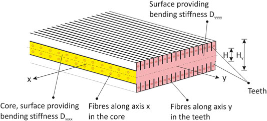
FIGURE 10. Local micro-structure of the meta-plate for cloaking flexural waves. The yellow (resp. pink) cross section provides the bending stiffness
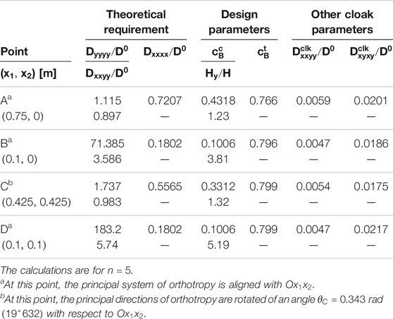
TABLE 2. Microstructural parameters of the boron/epoxy cloak for the transformation whose parameters are
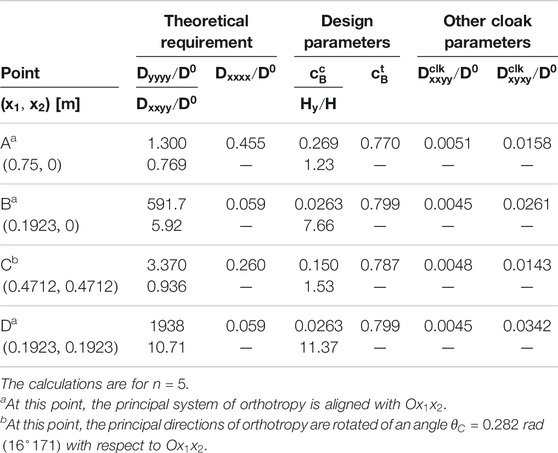
TABLE 3. Microstructural parameters of the boron/epoxy cloak for the transformation whose parameters are
Footnotes
1Uppercase and lowercase indices, both ranging between 1 and 2, are referred to reference and transformed domains, respectively, whereas a 0 in either super- or sub-script position indicates that the quantity concerned is evaluated in the reference configuration.
2ϵ plays the role of regularisation parameter for the construction of a near cloak (Kohn et al., 2008) in which the material properties at the inner boundary of the cloak are not singular.
3The summation over the repeated index is implied throughout the paper.
4With this set of parameters, it turns out that for the trapezoid
5In particular,
References
Bigoni, D., Gei, M., and Movchan, A. B. (2008). Dynamics of a prestressed stiff layer on an elastic half space: filtering and band gap characteristics of periodic structural models derived from long-wave asymptotics. J. Mech. Phys. Solid. 56, 2494–2520. doi:10.1016/j.jmps.2008.02.007
Brun, M., Colquitt, D. J., Jones, I. S., Movchan, A. B., and Movchan, N. V. (2014). Transformation cloaking and radial approximations for flexural waves in elastic plates. New J. Phys. 16, 093020. doi:10.1088/1367-2630/16/9/093020
Brun, M., Guenneau, S., and Movchan, A. B. (2009). Achieving control of in-plane elastic waves. Appl. Phys. Lett. 94, 061903. doi:10.1063/1.3068491
Chen, Y., Hu, J., and Huang, G. (2016). A design of active elastic metamaterials for control of flexural waves using the transformation method. J. Intell. Mater. Syst. Struct. 27, 1337–1347. doi:10.1177/1045389x15590273
Chung, J., and Hulbert, G. M. (1993). A time integration algorithm for structural dynamics with improved numerical dissipation: the generalized-α method. J. Appl. Mech. 60, 371–375. doi:10.1115/1.2900803
Chung, J., and Hulbert, G. M. (1994). A family of single-step houbolt time integration algorithms for structural dynamics. Comput. Methods Appl. Mech. Eng. 118, 1–11. doi:10.1016/0045-7825(94)90103-1
Climente, A., Torrent, D., and Sánchez-Dehesa, J. (2016). Analysis of flexural wave cloaks. AIP Adv. 6, 121704. doi:10.1063/1.4968611
Colquitt, D. J., Brun, M., Gei, M., Movchan, A. B., Movchan, N. V., and Jones, I. S. (2014). Transformation elastodynamics and cloaking for flexural waves. J. Mech. Phys. Solid. 72, 131–143. doi:10.1016/j.jmps.2014.07.014
Darabi, A., Zareei, A., Alam, M.-R., and Leamy, M. J. (2018). Experimental demonstration of an ultrabroadband nonlinear cloak for flexural waves. Phys. Rev. Lett. 121, 174301. doi:10.1103/physrevlett.121.174301
Farhat, M., Guenneau, S., and Enoch, S. (2009a). Ultrabroadband elastic cloaking in thin plates. Phys. Rev. Lett. 103, 024301. doi:10.1103/PhysRevLett.103.024301
Farhat, M., Guenneau, S., Enoch, S., and Movchan, A. B. (2009b). Cloaking bending waves propagating in thin elastic plates. Phys. Rev. B 79, 033102. doi:10.1103/PhysRevB.79.033102
Futhazar, G., Parnell, W. J., and Norris, A. N. (2015). Active cloaking of flexural waves in thin plates. J. Sound Vib. 356, 1–19. doi:10.1016/j.jsv.2015.06.023
Gei, M. (2008). Elastic waves guided by a material interface. Eur. J. Mech. Solid. 27, 328–345. doi:10.1016/j.euromechsol.2007.10.002
Halpin, J. C., and Kardos, J. L. (1976). Halpin-tsai equations: a review. Polym. Eng. Sci. 16, 344–352. doi:10.1002/pen.760160512
Hughes, T. (1987). The finite element method - linear static and dynamic finite element analysis. Upper Saddle River, NJ: Prentice-Hall.
Kohn, R. V., Shen, H., Vogelius, M. S., and Weinstein, M. I. (2008). Cloaking via change of variables in electric impedance tomography. Inverse Probl. 24, 015016. doi:10.1088/0266-5611/24/1/015016
Lekhnitskii, S., Tsai, S., and Cheron, T. (1968). Anisotropic plates. New York, NY: Gordon and Breach.
Liu, M., and Zhu, W. D. (2019). Nonlinear transformation-based broadband cloaking for flexural waves in elastic thin plates. J. Sound Vib. 445, 270–287. doi:10.1016/j.jsv.2018.12.025
Milton, G. W., Briane, M., and Willis, J. R. (2006). On cloaking for elasticity and physical equations with a transformation invariant form. New J. Phys. 8, 248. doi:10.1088/1367-2630/8/10/248
Misseroni, D., Colquitt, D. J., Movchan, A. B., Movchan, N. V., and Jones, I. S. (2016). Cymatics for the cloaking of flexural vibrations in a structures plate. Sci. Rep. 6, 23929. doi:10.1038/srep23929
Misseroni, D., Movchan, A. B., and Bigoni, D. (2019). Omnidirectional flexural invisibility of multiple interacting voids in vibrating elastic plates. Proc. R. Soc. A 475, 2229. doi:10.1098/rspa.2019.0283
Mroz, A. (2011). Stability analysis of a plane, rectangular, boron-epoxy laminated plate basing on strength properties determined by different methods. Mech. Mech. Eng. 15, 161–181.
Ning, L., Wang, Y.-Z., and Wang, Y.-S. (2020). Active control cloak of the elastic wave metamaterial. Int. J. Solid Struct. 202, 126–135. doi:10.1016/j.ijsolstr.2020.06.009
Norris, A. N., and Shuvalov, A. L. (2011). Elastic cloaking theory. Wave Motion. 48, 525–538. doi:10.1016/j.wavemoti.2011.03.002
O’Neill, J., Selsil, O., McPhedran, R. C., Movchan, A. B., and Movchan, N. V. (2015). Active cloaking of inclusions for flexural waves in thin elastic plates. Q. J. Mech. Appl. Math. 68, 263–288. doi:10.1093/qjmam/hbv007
Petera, J., and Pittman, J. F. T. (1994). Isoparametric hermite elements. Int. J. Numer. Meth. Engng. 37, 3489–3519. doi:10.1002/nme.1620372006
Petyt, M. (1990). An introduction to the finite element method. Cambridge, UK: Cambridge University Press.
Stenger, N., Wilhelm, M., and Wegener, M. (2012). Experiments on elastic cloaking in thin plates. Phys. Rev. Lett. 108, 014301. doi:10.1103/PhysRevLett.108.014301
Timoshenko, S., and Woinowsky-Krieger, S. (1959). Theory of plates and shells. New York, NY: McGraw-Hill.
Zareei, A., and Alam, M.-R. (2017). Broadband cloaking of flexural waves. Phys. Rev. E 95, 063002. doi:10.1103/PhysRevE.95.063002
Keywords: meta-materials, transformation elastodynamics, invisibility cloak, wave propagation, finite element method
Citation: Rossi M, Veber D and Gei M (2020) Numerical Assessment of the Performance of Elastic Cloaks for Transient Flexural Waves. Front. Mater. 7:603667. doi: 10.3389/fmats.2020.603667
Received: 07 September 2020; Accepted: 12 October 2020;
Published: 27 November 2020.
Edited by:
Andrea Bacigalupo, University of Genoa, ItalyCopyright © 2020 Rossi, Veber and Gei. This is an open-access article distributed under the terms of the Creative Commons Attribution License (CC BY). The use, distribution or reproduction in other forums is permitted, provided the original author(s) and the copyright owner(s) are credited and that the original publication in this journal is cited, in accordance with accepted academic practice. No use, distribution or reproduction is permitted which does not comply with these terms.
*Correspondence: Massimiliano Gei, bWFzc2ltaWxpYW5vLmdlaUBkaWEudW5pdHMuaXQ=
†Current address: Department of Engineering and Architecture, University of Trieste, Trieste, Italy.