 Fang Liu
 Fuxiao Yu
 Dazhi Zhao
 Li Gao
- Key Laboratory of Lightweight Structural Materials, School of Materials Science and Engineering, Northeastern University, Shenyang, China
The fatigue life of a hot extruded Al-12.7Si-0.7Mg alloy under T1, T4, and T6 conditions was studied. The microstructure and tensile properties of the alloy were investigated in order to analyze the fatigue behavior. The results of the fatigue test showed that an extruded Al-12.7Si-0.7Mg alloy provided greater fatigue life compared to a cast Al-Si alloy, which was explained by the refined microstructure characterized by fine Si particles uniformly distributed in the Al matrix of fine equiaxed grains promoted by hot extrusion. The fatigue property of the alloy in T6 treatment was higher than that in the T4 and T1 conditions due to strengthening precipitation.
Introduction
Wrought Al-Si alloys for structural application have been generated by the combination of direct chill casting and plastic deformation (Yu et al., 2005). The microstructure of the deformed Al-12.7Si-0.7Mg alloy consists of fine and uniformly distributed Si particles on equiaxed Al grain boundaries. The alloy after artificial aging treatment exhibits good ductility and much higher proof strength as well as tensile strength compared to the 6,063 alloy, as the result of the microstructure feature (Yu et al., 2005; Liu et al., 2011).
In terms of casting Al-Si alloys, many researchers have indicated that casting defects like porosity is one factor which effects the fatigue performance (Casellas et al., 2005; Yi et al., 2006; Atxaga et al., 2013). Microstructure features including eutectic silicon characteristics (i.e., size and morphology) (Casellas et al., 2005; Ammar et al., 2008; Mbuya et al., 2011), secondary dendrite arm spacing (SDAS) (Yi et al., 2004; Shaha et al., 2015), and intermetallic compounds also influence the fatigue properties. Mbuya et al. (2011) found that larger-sized Si particles and elongated particles are more likely to cause crack initiation than average-sized Si particles. In addition, a fine microstructure with smaller SDAS and cell size could increase the fatigue life (Yi et al., 2004; Shaha et al., 2015).
The fatigue properties of wrought Al-Mg-Si alloys have also been studied. Coarse intermetallic secondary phases, Mg2Si metastable phase, and surface qualities influence the fatigue properties (Borrego et al., 2004; Azzam et al., 2010). The wrought Al-12.7Si-0.7Mg alloy has the same elements as wrought Al-Mg-Si alloys. However, it should be pointed out that the microstructure of the wrought Al-Si alloy distinguishes itself from that of most wrought Al-Mg-Si alloys, by its fine equiaxed grains in the Al matrix and the uniform distribution of fine Si particles on the grain boundaries (Liu et al., 2011). Compared to a casting Al-Si alloy, the Si morphology distribution of the wrought Al-12.7Si-0.7Mg alloy is dispersed due to hot-deformation (Liu et al., 2011). There are few studies reporting the fatigue behavior of extruded Al-Si alloys (Ham et al., 2017; Wang et al., 2018).
In this paper, the fatigue properties of the wrought Al-12.7Si-0.7Mg alloy were investigated to fully supplement the previously unaddressed properties of the newly developed structural applications for the Al-Si alloy when it is under repeated cyclic loading.
Materials and Methods
An extruded Al-12.7Si-0.7Mg alloy rod was studied, which was produced by direct chill casting and then hot extruded. The diameter of the extruded rod was 12 mm. The extruded bar (T1) was subjected to T4 (solution treatment + nature aging) and T6 (solution treatment + artificial aging) heat treatment carried out in a Muffle furnace. The solution treatment of the sample was performed at 540°C for 90 min and quenched into water at room temperature. After quenching, artificial aging of the specimens was carried out at 180°C for 3 h.
Mechanical tests were performed on a SHIMADZU AG-X plus testing machine at a cross-head speed of 0.2 mm/min. The mechanical properties of the alloy in different conditions were the average for three specimens. Fatigue tests were performed on a fatigue testing machine (NYEEHF-EV200K2-040-1A) at a stress ratio of -1 using a sinusoidal cycle at a frequency of 20 Hz at room temperature. Figure 1 shows the dimension of the specimen for the mechanical test and fatigue test. Based on tensile test results, the cyclic maximum stress levels of the extruded alloy (T1) were set to 130, 140, 150, 160, and 180 MPa, respectively. The cyclic maximum stress levels of the T4 condition were set to 150, 160, 170, 180, and 190 MPa, respectively. The cyclic maximum stress levels of the T6 condition were set to 170, 180, 190, 200, 210, and 220 MPa, respectively. Four fatigue specimens were tested at each stress level to obtain the average fatigue life. The fatigue test was stopped at 2 × 10⁶ cycles without failure.
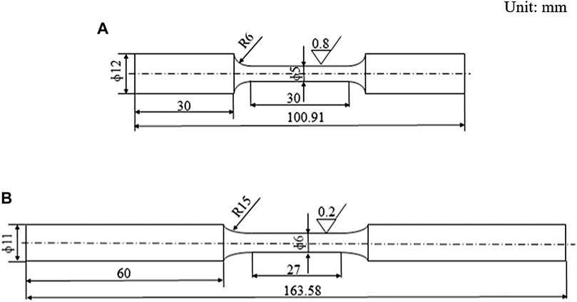
FIGURE 1. Dimension diagram of the specimen, (A) mechanical test, (B) fatigue test.
The microstructure of the alloys in the T1, T4, and T6 conditions were analyzed by an optical microscope (Olympus DSX500). In order to analyze the grain size, the EBSD band contrast image was carried out by FIB-SEM (crossbeam550). Image-Pro Plus image analysis software was used to investigate the Si particle size and matrix grain size. Conventional transmission electron microscope (TEM) observations were performed using a FEI Tecnai F20 electron microscope operated at 200 KV. TEM thin foils were prepared by double jet electropolishing with a solution of 30% nitric acid in methanol at −20°C and a voltage of 20 V. The fracture surfaces were studied by ZEISS Ultra Plus scanning electron microscopy (SEM) to determine the fracture mode.
Results and Discussion
Microstructure
The microstructures of the longitudinal (along the extrusion direction) section of the alloy are shown in Figure 2. Compared with the T1 condition, the solid solution treatment changed the size of the Si particles. Si particles were gradually round and their aspect ratio was decreased in the T4 condition. The grain size of the Al matrix on the cross-section (transverse to the extrusion direction) of the extruded alloy was analyzed by electron back-scattered diffraction (EBSD). The EBSD band contrast images of the alloy under T1, T4, and T6 conditions are shown in Figure 3. Hot extrusion resulted in a uniform distribution of fine Si particles as well as other second phase particles in the Al matrix of fine equiaxed grains via dynamic recrystallization (Liu et al., 2011). After solution treatment, the Al grain size increased from 6.5 to 6.9 μm. It is worth noticing that the change of the size of the Si particles and the Al matrix grains was not considerable during solid solution treatment due to mutual restraint between the grain growth of the Al matrix and the coarsening of the Si particles.
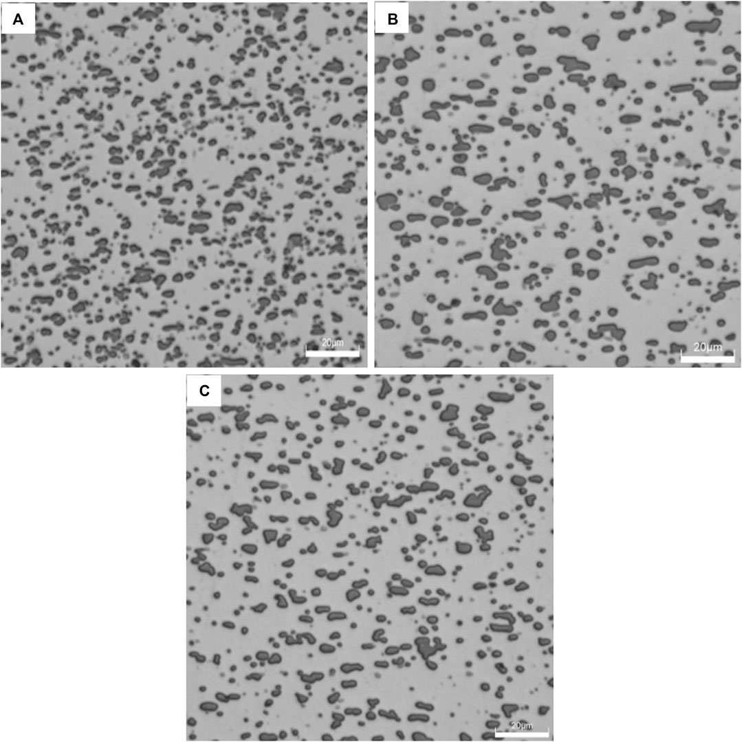
FIGURE 2. The optimal microstructure of the alloy in different conditions, (A) T1, (B) T4, (C) T6.
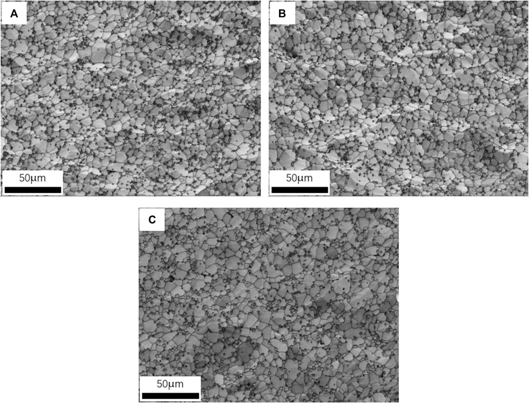
FIGURE 3. The EBSD band contrast images of the alloy in different conditions, (A) T1, (B) T4, (C) T6.
Figure 4 shows the TEM images (B = [110] Al) of the alloy in different conditions. It can be seen that in the T1 and T4 conditions a high density of dislocations in the Al matrix occurred. While needle-like precipitates were visible in the Al matrix in the T6 condition as shown in Figure 4C.
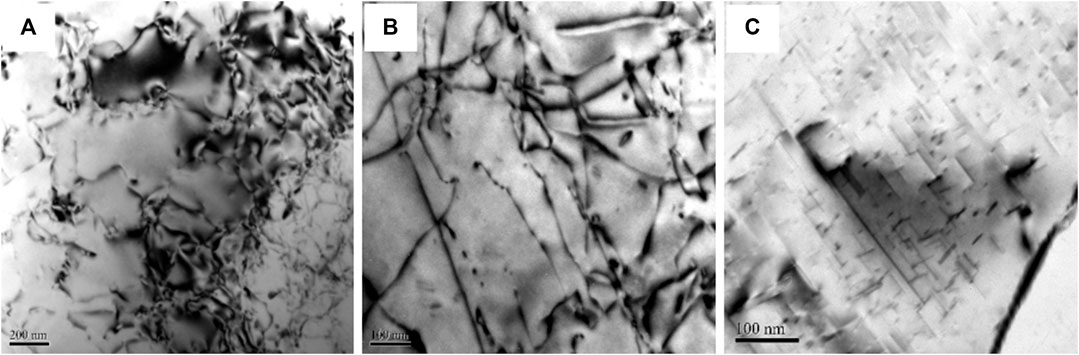
FIGURE 4. The TEM image of the alloy in different conditions, (A) T1, (B) T4, (C) T6.
Mechanical Properties
Table 1 lists the room temperature mechanical properties of the alloy in the three conditions. Yield strength (YS), ultimate tensile strength (UTS), and elongation of the alloy in T4 and T6 were much higher than that in the T1 condition. The Mg2Si phase was in the form of solute atoms in the matrix in the T4 condition which led to solid-solution strengthening (Liu et al., 2011). It is clear that precipitation hardening contributed to increased YS and UTS in T6 treatment. Precipitates and Si particles had a strong pinning effect on the movement of dislocations.
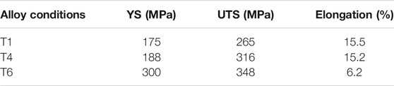
TABLE 1. Mechanical properties of the alloy in different conditions.
Fatigue Properties
The fatigue test data were fitted by the square method based on a linear correlation between fatigue life and fatigue strength as shown in Eq. 1. Table 2 lists the material constants of the samples under different conditions. And the fitted curve of the logarithmic scale was plotted, as shown in Figure 3.
N is the fatigue life, Cs and n are the material constants; and Smax is the maximum stress.
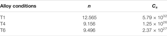
TABLE 2. Material constants of the alloy in different conditions.
Figure 5 shows the S-N curves of the alloy in the T1, T4, and T6 conditions. Fatigue lives of the alloy in each condition gradually increased with a decrease in stress amplitude. It is clearly shown that fatigue lives for the specimens in T4 and T6 treatment increased compared to the T1 condition at the same stress amplitude. The fatigue strength increased significantly in T4 and T6 after heat treatment. The optical microstructures and the EBSD band contrast image shown in Figures 2, 3 present information about the changes of the Si particles and the grain. In contrast, the Si particles were coarsened by solid solution treatment. There was no obvious change in grain size and Si particles after aging. However, there were obvious differences between that in the T6 condition and that in the T4 and T1 conditions according to the TEM images shown in Figure 4. Uniform and fine distribution of precipitates were observed in the matrix. It is obvious that considerable improvement in fatigue life and fatigue strength occurred, which was attributed to solution treatment and artificial aging.
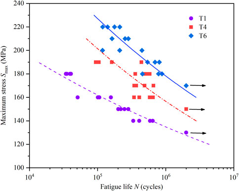
FIGURE 5. S-N curves of the Al-12.7Si-0.7Mg alloy in different conditions.
There have been no similar fatigue results of a wrought Al-Si alloy with similar compositions that could be compared with the results in this study. However, according to the study of Ammar et al. (2008), the fatigue life of A356 is between 106 and 4 × 10⁶ cycles when the stress amplitude is 68 MPa, and the value also depends on the size of the pore area. The stress amplitude in this study was much higher. Yi et al. (2004) investigated the fatigue life of an A356 alloy in the T6 condition which is comparable to the extruded Al-12.7Si-0.7Mg alloy at the same stress amplitudes. It would indirectly indicate that the extruded Al-12.7Si-0.7Mg alloy especially in the T4 and T6 conditions has excellent fatigue properties.
Fractography
Macroscopic views of the fatigue fracture surface of the alloy in different conditions are illustrated in Figure 6. It can be clearly seen that there is a fatigue crack initiation zone, crack propagation zone, and final fracture zone under each condition. The area of crack propagation zone in T6 condition is larger and more obvious than others.
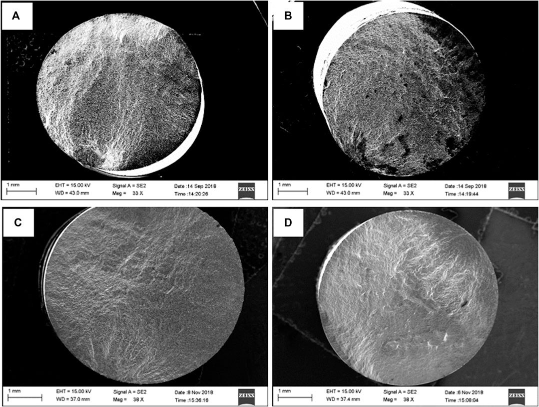
FIGURE 6. Macroscopic view of the fatigue fracture surface of the alloy in different conditions and stress amplitudes, (A) T1-160 MPa, (B) T4-160 MPa, (C) T4-190 MPa, (D) T6-190 MPa.
In order to investigate the fatigue crack initiation zone in detail, Figure 7 shows the fatigue crack initiation zone of the alloy in different conditions and stress amplitudes. The observation of fatigue crack initiation of the as-extruded alloy at 140 MPa is given in Figure 7A. As shown in the figure, the fatigue crack initiated a crystal slip as marked by the white line frame. Figures 7B,C indicate that the crack of the as-extruded alloy at 160 MPa and the as-solutioned alloy at 180 MPa alloy were from the specimen surface. The crack initiation site of the alloy in the T6 condition is shown in Figure 7D loaded with a stress amplitude of 180 MPa. There were silicon particles deboned from the matrix near the specimen surface. Based on the above observation, the crack initiation area was commonly from the surface. Even though crystal slip and interface debonding between the silicon and the matrix could be observed in Figures 7A,D, that is rare. In the cast Al-Si alloy, the defects at or near the sample surface, the larger size of eutectic Si, or intermetallic compounds acted as origin sites for crack nucleation. The wrought Al-Si alloy in this study had no casting defects due to hot extrusion. Strong interfacial bonding between the Si particle and the aluminum matrix existed because of the morphology of Si. Mbuya et al. (2011) concluded that larger-sized Si particles and elongated particles are more likely to cause crack initiation.
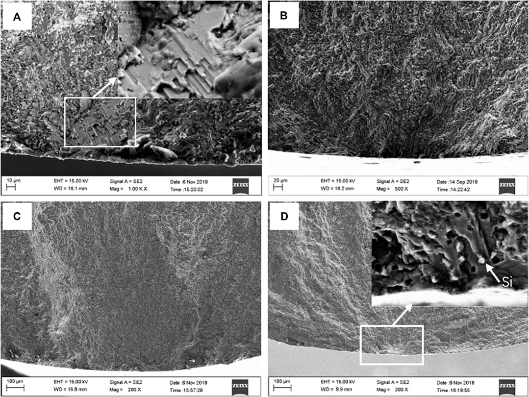
FIGURE 7. Fatigue crack initiation zone of the alloy in different conditions and stress amplitudes, (A) T1-140 MPa, (B) T1-160 MPa, (C) T4-180 MPa, (D) T6-180 MPa.
Figure 8 shows the crack propagation area of the alloy in different conditions. The areas are characterized by fatigue striations caused by several successive cycles. In Figures 8A,B, fatigue striations are accompanied by secondary cracks. The Si particles and precipitates in the T6 condition played a role in the strengthening phase by changing the crack propagation direction. The final fracture zone of the alloy is presented in Figure 9. It is noticeable that all tested conditions exhibited the characteristics of classic ductile fractures.
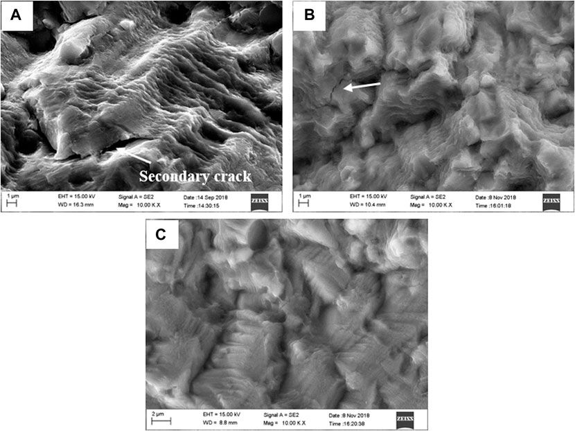
FIGURE 8. Fatigue crack propagation zone of the alloy in different conditions and stress amplitudes, (A) T1-160 MPa, (B) T4-180 MPa, (C) T6-180 MPa.
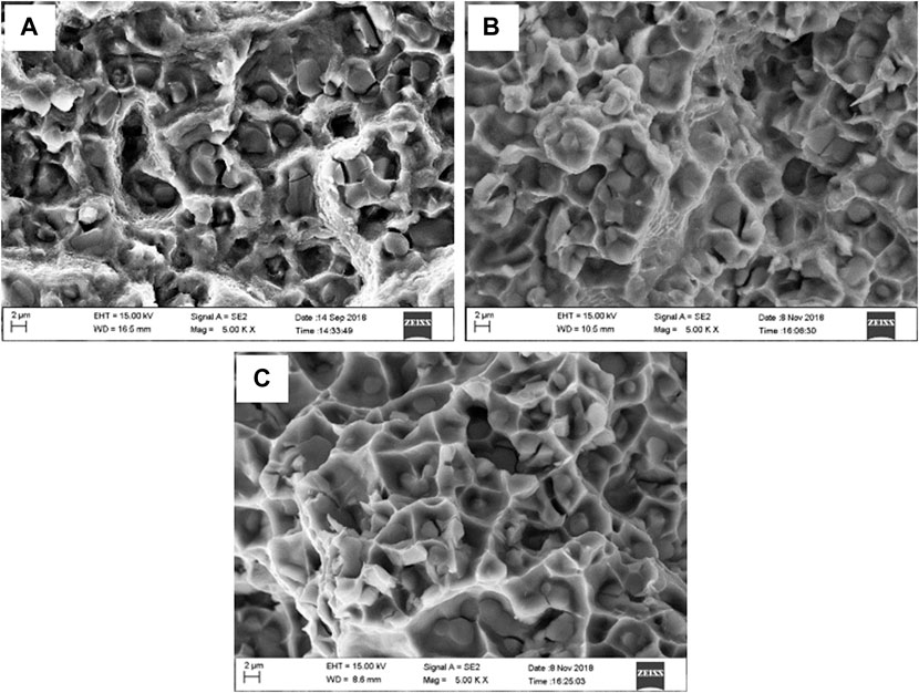
FIGURE 9. Final fracture zone of the alloy in different conditions and stress amplitudes, (A) T1-160 MPa, (B) T4-180 MPa, (C) T6-180 MPa.
Total fatigue life is dependent on crack initiation life and crack propagation life (Yi et al., 2004). The function of the Si particles of the studied alloy was to block the movement of dislocation. A high strain concentration would occur between the Si particle and Al matrix because of dislocation accumulation. Fatigue cracks may be formed either by cracking Si particles or along the interface between Si particles and the Al matrix at the point of reaching critical stress. The debonding of Si particles was observed, as shown in Figure 7D. After solid solution treatment, Si particles were gradually rounded and their aspect ratio decreased which is beneficial to extending crack initiation life and crack propagation life. In addition, the matrix was strengthened by Mg2Si in the form of solute atoms where crack growth rate and crack propagation are slow. The precipitates in the T6 condition further increased yield stress which decreased the number and size of the plastic deformation areas (Yi et al., 2004). Moreover, precipitates increased the resistance of the crack growth to produce a longer fatigue life.
Conclusion
An extruded Al-12.7Si-0.7Mg alloy has excellent fatigue properties due to the refined microstructure characterized by fine Si particles uniformly distributed in the Al matrix of fine equiaxed grains promoted by hot extrusion. The mechanical properties and fatigue properties of the alloy in T6 treatment was higher than that in the T4 and T1 conditions due to precipitation strengthening. Fatigue cracks were more likely to initiate from the specimen surface. Crystal slip bands and interface debonding between the silicon and matrix may act as crack initiation sites as was found to be the case in a certain sample tested.
Data Availability Statement
The original contributions presented in the study are included in the article/Supplementary Material, further inquiries can be directed to the corresponding author.
Author Contributions
FL designed the experiments, analyzed data and wrote the manuscript. FY designed the experiments and revised the manuscript. DZ performed the experimental work of preparing the studied alloy including casting and hot deformation. LG performed the experimental work of fatigue properties tests.
Funding
This work was funded by the National Key R&D Program of China (2017YFB0306402) and the National Natural Science Foundation of China under the grant nos. 50771030 and 51401047.
Conflict of Interest
The authors declare that the research was conducted in the absence of any commercial or financial relationships that could be construed as a potential conflict of interest.
References
Ammar, H. R., Samuel, A. M., and Samuel, F. H. (2008). Effect of Casting Imperfections on the Fatigue Life of 319-F and A356-T6 Al-Si Casting Alloys. Mater. Sci. Eng. A 473, 65–75. doi:10.1016/j.msea.2007.03.112
Atxaga, G., Pelayo, A., and Irisarri, A. M. (2013). Effect of Microstructure on Fatigue Behaviour of Cast Al-7Si-Mg Alloy. Mater. Sci. Technology 17 (4), 446–450. doi:10.1179/026708301101510023
Azzam, D., Menzemer, C. C., and Srivatsan, T. S. (2010). The Fracture Behavior of an Al-Mg-Si alloy during Cyclic Fatigue. Mater. Sci. Eng. A 527, 5341–5345. doi:10.1016/j.msea.2010.04.023
Borrego, L. P., Abreu, L. M., Costa, J. M., and Ferreira, J. M. (2004). Analysis of Low Cycle Fatigue in AlMgSi Aluminium Alloys. Eng. Fail. Anal. 11 (5), 715–725. doi:10.1016/j.engfailanal.2003.09.003
Casellas, D., Pérez, R., and Prado, J. M. (2005). Fatigue Variability in Al-Si Cast Alloys. Mater. Sci. Eng. A 398, 171–179. doi:10.1016/j.msea.2005.03.034
Ham, G. S., Baek, M. S., Kim, J. H., Lee, S. W., and Lee, K. A. (2017). Effect of Heat Treatment on Tensile and Fatigue Deformation Behavior of Extruded Al-12wt%Si Alloy. Met. Mater. Int. 23 (1), 35–42. doi:10.1007/s12540-017-6351-3
Liu, F., Yu, F., Zhao, D., and Zuo, L. (2011). Microstructure and Mechanical Properties of an Al-12.7Si-0.7Mg alloy Processed by Extrusion and Heat Treatment. Mater. Sci. Eng. A 528, 3786–3790. doi:10.1016/j.msea.2011.01.041
Mbuya, T. O., Sinclair, I., Moffat, A. J., and Reed, P. A. S. (2011). Analysis of Fatigue Crack Initiation and S-N Response of Model Cast Aluminium Piston Alloys. Mater. Sci. Eng. A 528, 7331–7340. doi:10.1016/j.msea.2011.06.007
Shaha, S. K., Czerwinski, F., Kasprzak, W., Friedman, J., and Chen, D. L. (2015). Effect of Solidification Rate and Loading Mode on Deformation Behavior of Cast Al-Si-Cu-Mg alloy with Additions of Transition Metals. Mater. Sci. Eng. A 636, 361–372. doi:10.1016/j.msea.2015.03.077
Wang, G. D., Tian, N., Li, C., Zhao, G., and Zuo, L. (2018). Effect of Si Content on the Fatigue Fracture Behavior of Wrought Al-xSi-0.7Mg Alloy. Msf 941, 1143–1148. doi:10.4028/www.scientific.net/msf.941.1143
Yi, J., Gao, Y., Lee, P., and Lindley, T. (2004). Effect of Fe-Content on Fatigue Crack Initiation and Propagation in a Cast Aluminum-Silicon alloy (A356-T6). Mater. Sci. Eng. A 386, 396–407. doi:10.1016/s0921-5093(04)00964-5
Yi, J. Z., Gao, Y. X., Lee, P. D., and Lindley, T. C. (2006). Microstructure-Based Fatigue Life Prediction for Cast A356-T6 Aluminum-Silicon Alloys. Metall. Materi Trans. B 37 (2), 301–311. doi:10.1007/bf02693159
Keywords: Al-Si alloy, extrusion, heat treatment, microstructure, fatigue, fractography
Citation: Liu F, Yu F, Zhao D and Gao L (2021) Fatigue Behavior of an Al-12.7Si-0.7Mg Alloy Processed by Extrusion and Heat Treatment. Front. Mater. 8:667771. doi: 10.3389/fmats.2021.667771
Received: 14 February 2021; Accepted: 03 May 2021;
Published: 09 June 2021.
Edited by:
Qi Chao, Deakin University, AustraliaReviewed by:
Lu Jiang, Deakin University, AustraliaXin Xin, Institute of Metals Research (CAS), China
Copyright © 2021 Liu, Yu, Zhao and Gao. This is an open-access article distributed under the terms of the Creative Commons Attribution License (CC BY). The use, distribution or reproduction in other forums is permitted, provided the original author(s) and the copyright owner(s) are credited and that the original publication in this journal is cited, in accordance with accepted academic practice. No use, distribution or reproduction is permitted which does not comply with these terms.
*Correspondence: Fuxiao Yu, Znh5dUBtYWlsLm5ldS5lZHUuY24=