 Dehui Ye
 Jie Tan
 Yabin Liang
 Qian Feng
- 1Key Laboratory of Earthquake Early Warning, Institute of Seismology, China Earthquake Administration, Wuhan, China
- 2Wuhan Institute of Earthquake Engineering Co. Ltd., Wuhan, China
The pounding tuned mass damper (PTMD) is a novel passive damper that absorbs and dissipates energy by an auxiliary tuned spring-mass system. Viscoelastic materials are attached to the interface of the limitation collar in the PTMD so that the energy dissipation capacity can be enhanced. Previous studies have successfully demonstrated the effectiveness of PTMD at room temperature. However, in practice, the PTMD may face a broad temperature range, which can affect the mechanical properties of the viscoelastic materials. Thus, the study of vibration control effectiveness of PTMD at different temperatures is of great significance for its practical engineering application. In this paper, a series of experiments were conducted to investigate the performance of a PTMD in a temperature-controlled environment. A PTMD device was designed to suppress the vibration of a portal frame structure and tested across environmental temperatures ranging from –20°C to 45°C. The displacement reduction ratios demonstrated the temperature robustness of the PTMD. Additionally, the numerical results validated the accuracy of the pounding force model and the performance of PTMD.
Introduction
It is nearly impossible for the engineers to fully predict the excitations of structures throughout their entire service lives (Shirai et al., 2019; Cai et al., 2020). Overdesigning the structure against all possible disturbances is often impractical and prohibitively expensive (Li et al., 2007; Ou et al., 2007; Zhang and Ou, 2008). Structural vibration control is a safe and economical approach to protect structures against severe disturbances such as expected in natural disasters (Xu et al., 2011; Teng et al., 2016; Wang et al., 2017a; Zhang et al., 2017; Tan et al., 2020). Such control can be accomplished through passive devices such as the pounding tuned mass damper (PTMD).
The PTMD is a novel and effective structure control technique, which can dissipate energy through an internal collision mechanism. The PTMD was first reported by Zhang et al. (Zhang et al., 2013) in 2013. The configuration and schematic of the typical PTMD proposed by Zhang et al. is illustrated in Figure 1A. In the PTMD, a mass is connected to the host structure by a spring, and the natural frequency of the spring-mass system is tuned closely to that of the host structure by changing the stiffness of the spring. The displacement of the tuned mass is restricted by two delimiters. The spring-mass system consumes energy similar to a tuned mass damper (TMD) when the displacement is small; however, when the displacement is large enough to induce collision between the mass and the delimiter, the PTMD effectively dissipates energy beyond the capacity of a TMD. In order to improve the vibration suppression capacity during the impact, an energy-dissipation material is bonded to the delimiters.
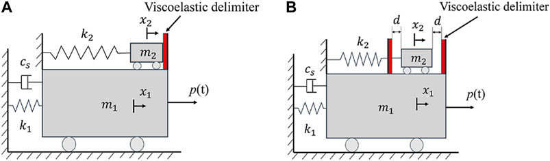
FIGURE 1. Typical configuration of the pounding tuned mass damper (PTMD): (A) Double-sided PTMD; (B) Single-sided PTMD.
Since then, researchers have demonstrated a wide range of applications for the PTMD and its remarkable effectiveness. Li et al. (Li et al., 2015) employed a PTMD to suppress the wind-induced vertical buffeting response of a traffic signal pole. The PTMD caused the damping ratios of the vertical vibration to increase to 4% from 1%. Allen et al. (Allen et al., 2016) employed PTMDs to control the vibrations of a submerged jumper. The seismic control performance of the PTMD was investigated by Xue et al. (Xue et al., 2016; Xue et al., 2017). A parameter study and impact fatigue of double-sided PTMD was performed by Zhang et al. (Zhang et al., 2015; Zhang et al., 2018). They found that the response is influenced by the mass ratio, the exciting force, and the gap between mass and the delimiters. These studies all showed the effective vibration control performance and robustness of the PTMD.
Based on the original double-sided PTMD, Wang et al. (Wang et al., 2017C) proposed a novel single-sided PTMD as shown in Figure 1B. In the single-sided PTMD, the tuned mass is set at the equilibrium position and is contact with energy-dissipation material. When the main mass begins to move due to external excitation, the tuned mass will impact the delimiter and dissipate kinetic energy during the collision. As shown by Zhang et al. (Zhang et al., 2015), the reduction ratio of the PTMD is related to many parameters including the mass ratio, the gap between the delimiter, and the pounding stiffness. The design of the single-sided PTMD does not require careful tuning of the gap between the mass the delimiter, thus affording it several significant advantages, such as a simple structure and ease of design. In addition, pounding in a single-sided PTMD occurs at the location where collisions occur at the highest velocity, which translates to high effectiveness and efficiency in the pounding mechanism. Furthermore, the tuned mass only moves toward one side, thereby opening up half of the working space, and improving the range of its applications.
The single-sided PTMD has been investigated through many theoretical and experimental studies. Wang et al. (Wang et al., 2017b; Wang et al., 2017c; Wang et al., 2018a; Wang et al., 2018b; Wang et al., 2019) studied single-sided the optimum PTMD design, including its control performance and impact force modelling through experiments and simulations. Tan et al. (Tan et al., 2019a; Tan et al., 2019b) designed a novel single-sided PTMD to control the vibration of a suspended piping system, and compared the control performances between PTMDs using viscoelastic materials versus shape memory alloy (SMA) sponges as the energy dissipating material.
Viscoelastic materials are extensively utilized as energy dissipating components due to their excellent combination of high energy dissipation capacity, low cost, and ease of manufacturing (Feng et al., 2018; Feng et al., 2020). However, a drawback of viscoelastic materials is that their mechanical properties are strongly influenced by temperature (Bergman and Hanson, 1993; Guo et al., 2009; Bhatti, 2013). In recent decades, extensive experimental and theoretical investigations on the mechanical properties of viscoelastic materials have been conducted (Zhong et al., 2017). Zhang et al. (Zhang et al., 2019) compared pounding stiffness and pounding damper ratio of viscoelastic materials between room temperature and 2°C, found that the pounding mechanical properties of viscoelastic materials changed considerably under different temperature conditions. At low temperatures, viscoelastic materials are in a glassy state, which is characterized by having a high modulus, a small loss factor and brittleness. In the glassy state, the viscoelastic material is typically destroyed when strain rate exceeds 5%. With the increase of temperature, materials return to the viscoelastic region, where the loss factor is the highest. As the temperature continues to rise, viscoelastic materials will be transformed into a highly elastic state, whereupon the shear modulus and loss factor begin to decrease.
When considering the effects of temperature, the shear modulus and loss factor are used to describe the properties of viscoelastic dampers. However, the pounding process has a high strain rate, which is different from the shear process. Therefore, to describe the properties of PTMD and analyze the structural dynamic responses with when the structure is equipped with the added PTMD, experiments are required. The parameters to demonstrate the mechanical properties of the pounding process are the pounding stiffness and the pounding damping, both of which are mostly neglected in prior literature.
Consequently, this paper presents an experimental study on the control performance for a PTMD over a wide range of temperatures. First, a single-sided PTMD is designed to control a single degree of freedom structure. The movement of the structure during free vibration and forced vibration are used to validate the effectiveness. Then, control tests are conducted repeatedly from –20°C to 45°C in temperature-controlled environment. The experimental results demonstrate the PTMD has a good temperature robustness and show that the control performance of PTMD can be gauged into three stages when the temperature increases. The originality of this work is that the vibration reduction performance of viscoelastic materials PTMD is experimentally studied within a wide temperature range. The results are significant for design and application of viscoelastic materials PTMD.
Theoretical Foundation
In this section, the related theoretical foundations of PTMD are briefly introduced, including structure-PTMD coupled equation of motion and the pounding force model. In addition, the effect of temperature on viscoelastic materials is described subsequently.
Structure-PTMD Coupled Equation of Motion
A structure with PTMD is modelled in Figure 1B. The mass, stiffness, damping coefficient of structure are respectively denoted by
where
Pounding Force Model
A linear viscoelastic model has been proposed to describe the contacting force
where
where
However, the linear viscoelastic model may produce a negative force at the end of impact, which is not consistent with experimental observation (Jankowski, 2005). Subsequently, a modified linear viscoelastic model (Mahmoud and Jankowski, 2011), divides the pounding into two individuals periods and assumes that energy loss only happens when the material experiences compression, is given by Eq (9):
where c has same form as in Eq (7), and the pounding damping ratio
Given its simplicity, the modified linear viscoelastic model can be easily implemented for numerical simulations. However, at the beginning of impact, a sudden rise of impact force may occur as a result of nonzero relative velocity. In order to overcome disadvantages of the modified linear viscoelastic model, a nonlinear viscoelastic model was introduced by Jankowski (Jankowski, 2005;2006). And it is expressed in Eq (11):
where c has the form in Eq (12):
where the pounding damping ratio
Temperature Effect of Viscoelastic Materials
The influence of temperature on the behavior of viscoelastic layers, viscoelastic dampers and structures with viscoelastic dampers were analyzed by many researchers (Chang et al., 1992; Park and Min, 2010; Guo et al., 2016). In one of their works, Chang et al. (Chang et al., 1992) tested a simple solid viscoelastic damper at different ambient temperatures and established empirical formulas that described the temperature dependence of the damper and loss factor. Previous studies(Tsai, 1994; Park and Min, 2010; Guo et al., 2016) have shown that different kinds of viscoelastic materials have similar dependencies on temperature, but differ in the specifics. Figure 2 shows the typical changes of shear modulus and loss factor of viscoelastic materials to changes in temperature. Note that Tg is the transition temperature of viscoelastic materials.
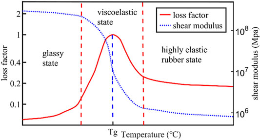
FIGURE 2. Variation curves of shear modulus and loss factor of viscoelastic materials with temperature increase.
The figure indicates that the shear modulus and loss factor of viscoelastic materials change with temperature, and viscoelastic materials have high damping in the characteristic temperature range. Additionally, the changes can be divided into three phases:
(1) At low temperature, the viscoelastic materials are in the glassy state. The material molecules undergo ordinary elastic deformation under the action of external force, and the material possesses high rigidity, high modulus and small loss factor;
(2) With the increase of the temperature, the materials return to viscoelastic state. The modulus of materials decreases sharply by several orders of magnitude. The loss factor also changes greatly and passes through a peak value (i.e. damping peak), which is equivalent to the maximum loss factor at the glass transition temperature. This transition zone is usually the temperature at which most viscoelastic materials are used.
(3) At high temperature, the viscoelastic materials are in the highly elastic rubber state. The modulus value is small, the loss factor is moderate. Both the modulus and loss factor of materials change slowly as the temperature increases.
Despite the known features described above, the relationship between the pounding stiffness
Experimental Setup
The experimental system consists of three parts: the experimental device and equipment, a portal frame, and a specially designed single-sided PTMD.
In the experiment, a portal frame with a single degree of freedom served as the primary structure, a PTMD was designed to control the displacements of the frame. The forced vibration experiments were conducted at temperature conditions ranging from –20°C to 45°C. The detail of temperatures in the experiment are listed in Table 1.
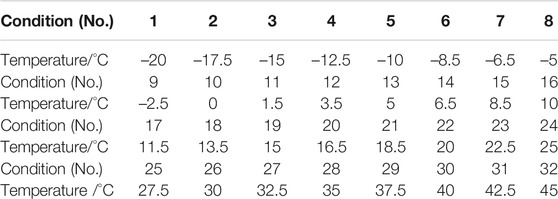
TABLE 1. Experimental conditions.
Experimental Device and Equipment
Figure 3A shows the experimental device and equipment. A noncontact laser displacement senor (HG-C1400, Panasonic Industrial Devices, China) measured the displacements of the frame. A data acquisition board (NI USB-6363, National Instruments, USA) recorded sensor signals at a sampling frequency of 1 kHz. An eccentric motor (JGB37-3650, Xytmotor, China) fixed to the frame provided the exciting force.
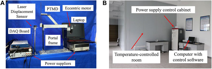
FIGURE 3. (A) Experimental device and equipment; (B) Temperature-controlled lab.
As shown in Figure 3B, the temperature experiment is carried out in the temperature-controlled room (MW-BD1824, Ziweiheng testing equipment, China). The temperature of the room can be adjusted from –20°C to 50°C.
Portal Frame
As shown in Figure 4, the portal frame is composed of an aluminum block, two spring steel columns, and an aluminum plate base. The detailed parameters of the portal frame are listed in Table 2. The aluminum block is served as the main structural mass. Spring steels served as structural columns because of its high fatigue performance and high elasticity. The base fixes the portal frame to the ground. The free vibration experiment was conducted by applying an initial displacement to the portal frame and releasing. The experimental result shows that the equivalent viscous damping ratio is 0.29%.
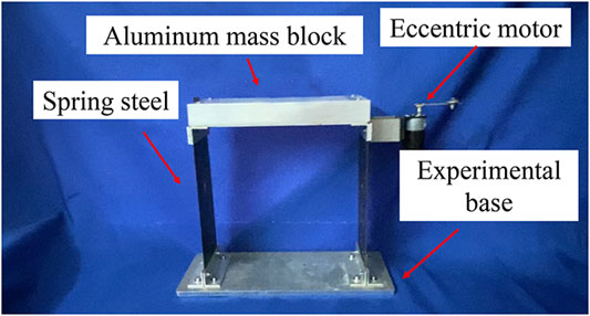
FIGURE 4. Portal frame and its components.

TABLE 2. Parameters of Portal frame.
A motor is attached to the top of the frame. A quasi-periodic disturbance is generated when the motor rotates. The generated frequency can be controlled by adjusting the excitation voltage motor. In the forced vibration experiments, the structure was excited at twenty different sweep frequency conditions ranging from 2.6Hz to 5Hz. The experimental results indicate that portal frame reaches the maximum displacement when the excitation frequency is 3.13Hz.
Design of PTMD
As shown in Figure 5, the single-sided PTMD consists of mass block, spring steel, and a viscoelastic delimiter (EVA sponge, produced by 3M). An aluminum pole connects the PTMD to the portal frame. To avoid affecting the dynamic characteristics of the structure, the pole of the PTMD consisted of aluminum. The optimum frequency of the PTMD,
where
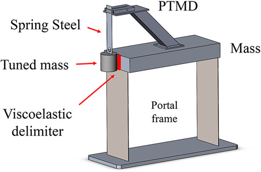
FIGURE 5. Portal frame with PTMD.
The weight of the tuned masses is 246g, and the corresponding mass ratio is 4.7%. A coupon of spring steel connected the tuned mass to the PTMD body. This design is an update of prior designs in which a nylon rope served as the connector and sometimes suffer from circular, out-of-plane motions (Tan et al., 2019b).
Experimental Results and Analysis
Preliminary Test of PTMD at Room Temperature
At first, the free vibration and forced vibration experiments with and without PTMD control were carried out at room temperature (18°C).
Figure 6 shows the free vibration of the portal frame with and without PTMD control. With PTMD control, the displacement of the frame rapidly reduced to a very small level compared to the case without control. The time taken to suppress the displacement from 10mm to 2mm reduced from 57.4s to 1.19s. The damping ratio of the system is correspondingly increased from 0.29% to 4.4%.
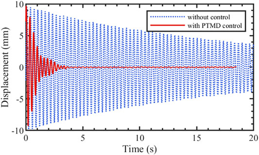
FIGURE 6. Displacement response of portal frame in time domain.
The displacements during forced vibration experiment are shown in Figure 7. The blue line describes the frequency response of the portal frame with PTMD control. The frequency response curve only has one peak at 3.13Hz, and the maximum displacement is 18.43mm, which occurred on the right side of the uncontrolled resonance frequency. Additionally, the peak displacement of the controlled vibration is 3.26mm, which is 17.7% of the uncontrolled resonant amplitude.
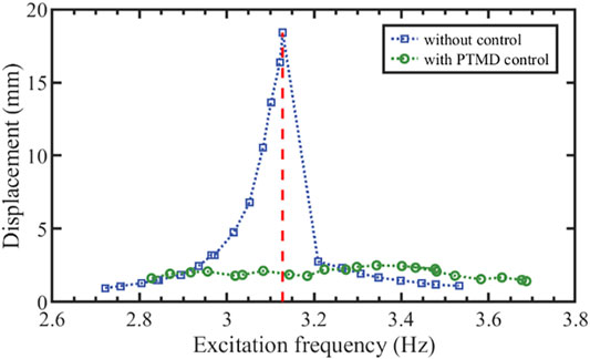
FIGURE 7. Displacement response of portal frame in frequency domain.
Figure 8 shows the vibration response of the portal frame before and after the PTMD is released. After the release of the PTMDs, the portal frame reached a new steady state in a short time. The displacement amplitude decreased from 16.34mm to 2.61mm.
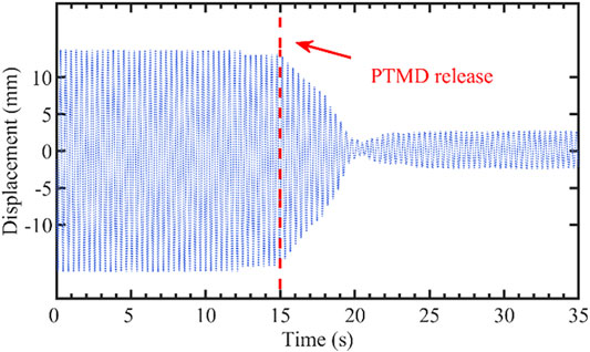
FIGURE 8. Displacement response of forced vibration with PTMD release.
Experiment on the Effect of Temperature on PTMD Control
The experiment on the effect of temperature on PTMD control was carried out in the temperature-controlled room. The forced vibration test in Preliminary test of PTMD at room temperature was repeated at different temperatures (listed in Table 1). The maximum displacements of the structure with PTMD at different temperatures are shown in Figure 9. As can be seen in Figure 9, the control performance of PTMD can be divided to three phases. In Phase 1 (–20°C to –8.5°C), the displacement of portal frame decreased slightly from 4.4mm to 4.34mm, and the reduction ratio increased from 76.1% to 76.4%. In Phase 2 (–8.5°C to 20°C), the maximum displacement of portal frame decreased first before decreasing. The corresponding reduction ratio increased first before decreasing. The maximum displacement decreased to 2.5mm at 10°C. In the meantime, the maximum reduction ratio reached 86.4%. In Phase 3 (20°C to 45°C), the displacement and reduction ratio remained almost constant (3.26mm and 82.3%, respectively) despite further changes in temperature.
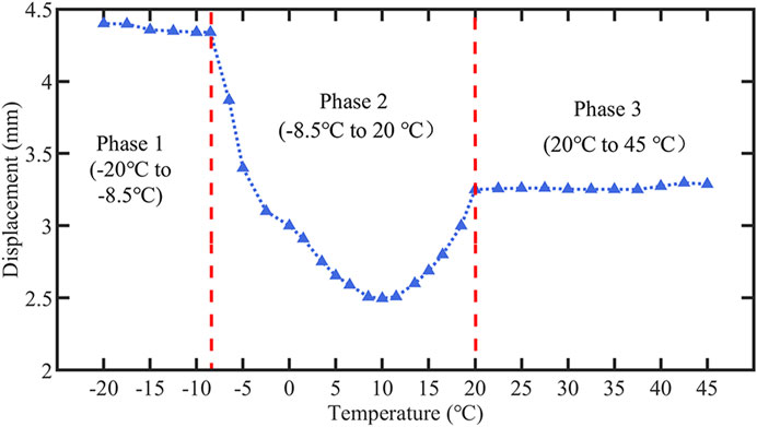
FIGURE 9. Displacement response of portal frame in frequency domain.
At glassy stage, the damping effect of PTMD almost does not change obviously with temperature variation. For the viscoelastic region (–8.5°C to 20°C), the damping effect of the PTMD changes with temperature, and there is an optimal control temperature, which is around 10°C for this viscoelastic material. Between 20–45°C the material behaved elastically, and the damping effect of PTMD remained in a steady state.
Although the damping effect is affected at low and high temperatures, the maximum displacement of the structure can still be reduced beyond 75%. As the thermal influence on PTMD control performance can be divided to three phases, results of each phase for the forced vibration experiments are shown in Figure 10. The results shows that PTMD has a good temperature robustness.
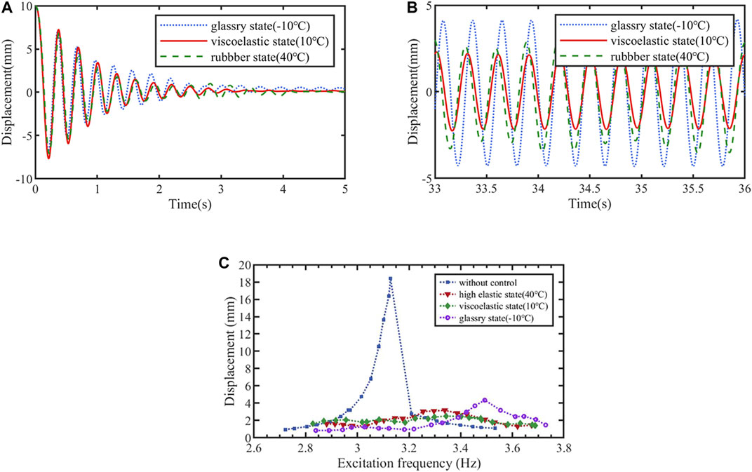
FIGURE 10. Displacement response of the portal frame at different state: (A) Free vibration in time domain; (B) Resonant vibration in time domain; (C) Forced vibration in the frequency domain.
Numerical Results
Impact Test and Validation of the Pounding Force Model
An impact test at 18°C was carried out to study the performance of the viscoelastic material during the impact. The experimental setup is shown in Figure 11. The spring steel-mass system was the same as in Experimental device and equipment, and the thickness of the viscoelastic materials was also set to 7mm (2 layers). An initial displacement of 35mm was applied to the mass and then released, allowing the mass pounds the viscoelastic material freely. The displacement of the mass was recorded by a laser displacement sensor, and a force sensor was used to record the pounding force during the experiment.
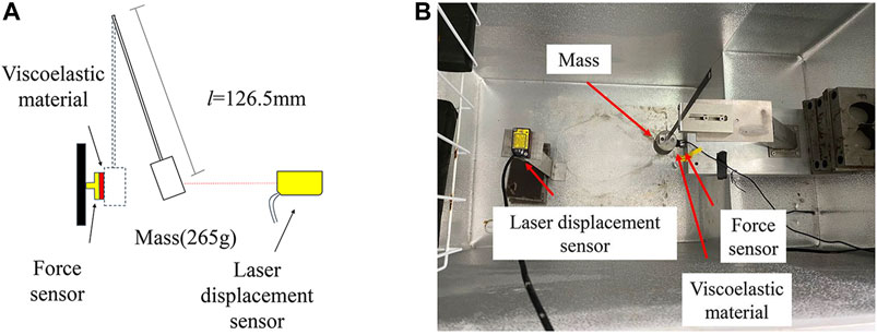
FIGURE 11. (A) Diagram of impact test setup; (B) Photo of experimental setup.
The results of the impact test are shown in Figure 12. Figure 12A, B are the time history records of mass displacement and impact force, respectively. Calculated from the initial displacement (35.00mm) and the rebound displacement (15.33mm) after the first impact, the coefficient of restitution
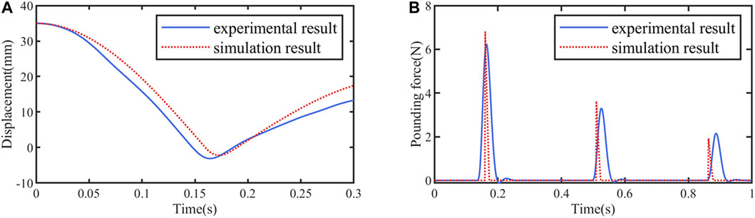
FIGURE 12. The results of the impact test: (A) Time history records of mass displacement; (B) Time history records of impact force.
Ignoring the damping of the spring steel, motion equation of the mass in Figure 11 can be expressed as
where
Numerical study on PTMD
To further validate the accuracy of the PTMD model, a simulation analysis was performed on the experimental structure with PTMD in Experimental setup. The motion equations of the structure with PTMD were expressed in eq (1) to eq (4), and the pounding force model was expressed in eq (11) to eq (13). In the free vibration, the excitation force
where
The parameters of the simulation at 18°C were derived from the results of the previous experiments and were summarized in Table 3. Similarly, Runge-Kutta method was utilized to solve the coupled equations, and both free vibration case and forced resonant case were simulated. The simulation results are plotted in Figure 13. As shown in Figure 13A and Figure 13B, the proposed coupled equations can high accurately predict dynamic response of structure with PTMD in both cases.

TABLE 3. Parameters of simulation.
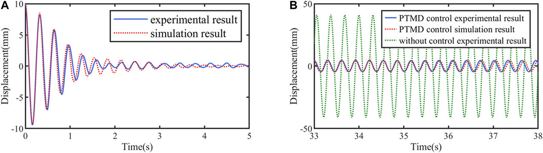
FIGURE 13. Simulation results: (A) Free vibration case; (B) Forced resonant vibration case.
Conclusion and Future Work
Conclusion
In this study, a single-sided pounding tuned mass damper (PTMD) was designed to mitigate the vibration of a portal frame. From experimental results, the conclusions are as follows:
(1) A single-sided PTMD can reduce the structural dynamic response and improve the damping ratio of structure effectively;
(2) From –20°C to 45°C, the displacement reduction ratio remained above 75%, which demonstrates the temperature robustness of the PTMD. The highest reduction ratio (86.4%) occurred at 10°C;
(3) The displacement reduction ratios of the PTMD are affected by temperature. With the increase of temperature, the effectiveness of PTMD can be divided into three stages. From –8.5°C to 20°C, reduction ratio is sensitive to temperature, where the ratio increases first and then decreases. The reduction ratios at –8.5°C and 20°C are 76.4% and 82.4%, respectively. Between –20°C to –8.5°C the reduction effects decrease slightly with temperature variation, while between 20°C to 45°C, the reduction effects remained stable.
(4) The numerical results validated the accuracy of the pounding force model and the performance of PTMD.
Future Work
The changes of parameters in pounding force model at different temperatures are vital factors for simulation and theoretical analysis of PTMD. The exploration of a wide range of temperatures impact tests to establish the damping factor vs. temperature curve will be delegated as a future work.
Data Availability Statement
The original contributions presented in the study are included in the article/Supplementary Material, further inquiries can be directed to the corresponding authors.
Author Contributions
All authors discussed and agreed upon the idea and made scientific contributions. JT and QF conceived the original idea. DY and JT designed the experiments. DY and YL conducted the experiments, and analysed the data. DY and JT wrote the paper. QF revised the paper.
Funding
This research is partially supported by the Scientific Research Fund of the Institute of Seismology and the Institute of Crustal Dynamics, China Earthquake Administration (Grant Number IS201616250) and the National Natural Science Foundation of China (Grant Number 51808092).
Conflict of Interest
JT, YL and QF were employed by Wuhan Institute of earthquake Engineering Co. Ltd.
The remaining author declares that the research was conducted in the absence of any commercial or financial relationships that could be construed as a potential conflict of interest.
References
Allen, J. K., Patil, D., Ho, S. C. M., Hirsch, R., Zhang, P., Parvasi, S. M., et al. (2016). Application of the Pounding Tuned Mass Damper to a Submerged Jumper Experiencing Horizontal and Vertical Vibrations. Earth Space 2016. 1109–1116. doi:10.1061/9780784479971.108
Anagnostopoulos, S. A. (1988). Pounding of Buildings in Series during Earthquakes. Earthquake Engng. Struct. Dyn. 16, 443–456. doi:10.1002/eqe.4290160311
Anagnostopoulos, S. A. (2004). Equivalent Viscous Damping for Modeling Inelastic Impacts in Earthquake Pounding Problems. Earthquake Engng. Struct. Dyn. 33, 897–902. doi:10.1002/eqe.377
Bergman, D. M., and Hanson, R. D. (1993). Viscoelastic Mechanical Damping Devices Tested at Real Earthquake Displacements. Earthquake Spectra 9, 389–417. doi:10.1193/1.1585722
Bhatti, A. Q. (2013). Performance of Viscoelastic Dampers (VED) under Various Temperatures and Application of Magnetorheological Dampers (MRD) for Seismic Control of Structures. Mech. Time-depend Mater. 17, 275–284. doi:10.1007/s11043-012-9180-2
Cai, W., Yu, B., Wu, F., and Shao, J. (2020). Seismic Response and Vibration Reduction Analysis of Suspended Structure under Wave Passage Excitation. Adv. Civil Eng. 2020, 1–3. doi:10.1155/2020/6468181
Chang, K. C., Soong, T. T., Oh, S. T., and Lai, M. L. (1992). Effect of Ambient Temperature on Viscoelastically Damped Structure. J. Struct. Eng. 118, 1955–1973. doi:10.1061/(asce)0733-9445(1992)118:7(1955)
Feng, Q., Fan, L., Huo, L., and Song, G. (2018). Vibration Reduction of an Existing Glass Window through a Viscoelastic Material-Based Retrofit. Appl. Sci. 8, 1061. doi:10.3390/app8071061
Feng, Q., Fan, L., Cai, S., Huo, L., and Liang, Y. (2020). A New Approach to Retrofitting an Existing Roller Door by Using Viscoelastic Materials for Vibration Reduction with Experimental Verification. Int. J. Struct. Stab. Dyn. 20, 2040008. doi:10.1002/9781119566557
Goldsmith, W. (1960). Impact: The Theory and Physical Behavior of Colliding Solids. London: E. Arnold, 28, 639. doi:10.1115/1.3641808
Guo, Y., Meng, G., and Li, H. (2009). Parameter Determination and Response Analysis of Viscoelastic Material. Arch. Appl. Mech. 79, 147–155. doi:10.1007/s00419-008-0221-x
Guo, J. W.-W., Daniel, Y., Montgomery, M., and Christopoulos, C. (2016). Thermal-mechanical Model for Predicting the Wind and Seismic Response of Viscoelastic Dampers. J. Eng. Mech. 142, 04016067. doi:10.1061/(asce)em.1943-7889.0001121
Jankowski, R., Wilde, K., and Fujino, Y. (1998). Pounding of Superstructure Segments in Isolated Elevated Bridge during Earthquakes. Earthquake Engng. Struct. Dyn. 27, 487–502. doi:10.1002/(sici)1096-9845(199805)27:5<487::aid-eqe738>3.0.co;2-m
Jankowski, R. (2005). Non-linear Viscoelastic Modelling of Earthquake-Induced Structural Pounding. Earthquake Engng Struct. Dyn. 34, 595–611. doi:10.1002/eqe.434
Jankowski, R. (2006). Analytical Expression between the Impact Damping Ratio and the Coefficient of Restitution in the Non-linear Viscoelastic Model of Structural Pounding. Earthquake Engng Struct. Dyn. 35, 517–524. doi:10.1002/eqe.537
Li, H., Liu, M., Li, J., Guan, X., and Ou, J. (2007). Vibration Control of Stay Cables of the Shandong Binzhou Yellow River Highway Bridge Using Magnetorheological Fluid Dampers. J. Bridge Eng. 12, 401–409. doi:10.1061/(asce)1084-0702(2007)12:4(401)
Li, L., Song, G., Singla, M., and Mo, Y.-L. (2015). Vibration Control of a Traffic Signal Pole Using a Pounding Tuned Mass Damper with Viscoelastic Materials (II): Experimental Verification. J. Vibration Control. 21, 670–675. doi:10.1177/1077546313488407
Mahmoud, S., and Jankowski, R. (2011). Modified Linear Viscoelastic Model of Earthquake-Induced Structural Pounding. 35, 51–62. doi:10.1007/978-3-319-16324-6
Ou, J., Long, X., Li, Q. S., and Xiao, Y. Q. (2007). Vibration Control of Steel Jacket Offshore Platform Structures with Damping Isolation Systems. Eng. Structures 29, 1525–1538. doi:10.1016/j.engstruct.2006.08.026
Park, H.-I., and Min, C.-H. (2010). Temperature Effect on Vibration Characteristics of Viscoelastic Laminated Beam. Int. J. Offshore Polar Eng. 20, 118–124. doi:10.1007/s10999-010-9127-1
Shirai, K., Nagaoka, A., Fujita, N., and Fujimori, T. (2019). Optimal Damper Slip Force for Vibration Control Structures Incorporating Friction Device with Sway-Rocking Motion Obtained Using Shaking Table Tests. Adv. Civil Eng. 2019.
Tan, J., Jiang, J., Liu, M., Feng, Q., Zhang, P., and Ho, S. C. M. (2019a). Implementation of Shape Memory alloy Sponge as Energy Dissipating Material on Pounding Tuned Mass Damper: An Experimental Investigation. Appl. Sci. 9, 1079. doi:10.3390/app9061079
Tan, J., Michael Ho, S. C., Zhang, P., and Jiang, J. (2019b). Experimental Study on Vibration Control of Suspended Piping System by Single-Sided Pounding Tuned Mass Damper. Appl. Sci. 9, 285. doi:10.3390/app9020285
Tan, J., Zhang, P., Feng, Q., and Song, G. (2020). Passive Seismic Protection of Building Piping Systems—A Review. Int. J. Struct. Stab. Dyn. 20, 2030001. doi:10.1142/s0219455420300013
Teng, J., Xing, H. B., Lu, W., Li, Z. H., and Chen, C. J. (2016). Influence Analysis of Time Delay to Active Mass Damper Control System Using Pole Assignment Method. Mech. Syst. Signal Process. 80, 99–116. doi:10.1016/j.ymssp.2016.04.008
Tsai, C. S. (1994). Temperature Effect of Viscoelastic Dampers during Earthquakes. J. Struct. Eng. 120, 394–409. doi:10.1061/(asce)0733-9445(1994)120:2(394)
Wang, W., Dalton, D., Hua, X., Wang, X., Chen, Z., and Song, G. (2017a). Experimental Study on Vibration Control of a Submerged Pipeline Model by Eddy Current Tuned Mass Damper. Appl. Sci. 7, 987. doi:10.3390/app7100987
Wang, W., Hua, X., Wang, X., Chen, Z., and Song, G. (2017b). Advanced Impact Force Model for Low-Speed Pounding between Viscoelastic Materials and Steel. J. Eng. Mech. 143, 04017139. doi:10.1061/(asce)em.1943-7889.0001372
Wang, W., Hua, X., Wang, X., Chen, Z., and Song, G. (2017c). Optimum Design of a Novel Pounding Tuned Mass Damper under Harmonic Excitation. Smart Mater. Structures 26. doi:10.1088/1361-665x/aa69a3
Wang, W., Hua, X., Wang, X., Chen, Z., and Song, G. (2018a). Numerical Modeling and Experimental Study on a Novel Pounding Tuned Mass Damper. J. Vibration Control. 24, 4023–4036. doi:10.1177/1077546317718714
Wang, W., Wang, X., Hua, X., Song, G., and Chen, Z. (2018b). Vibration Control of Vortex-Induced Vibrations of a Bridge Deck by a Single-Side Pounding Tuned Mass Damper. Eng. Structures 173, 61–75. doi:10.1016/j.engstruct.2018.06.099
Wang, W., Hua, X., Chen, Z., Wang, X., and Song, G. (2019). Modeling, Simulation, and Validation of a Pendulum‐pounding Tuned Mass Damper for Vibration Control. Struct. Control. Health Monit. 26, e2326. doi:10.1002/stc.2326
Xu, Z.-D., Wang, D.-X., and Shi, C.-F. (2011). Model, Tests and Application Design for Viscoelastic Dampers. J. Vibration Control. 17, 1359–1370. doi:10.1177/1077546310373617
Xue, Q., Zhang, J., He, J., and Zhang, C. (2016). Control Performance and Robustness of Pounding Tuned Mass Damper for Vibration Reduction in SDOF Structure. Shock Vib. 2016, 1–15. doi:10.1177/1077546310373617
Xue, Q., Zhang, J., He, J., Zhang, C., and Zou, G. (2017). Seismic Control Performance for Pounding Tuned Massed Damper Based on Viscoelastic Pounding Force Analytical Method. J. Sound Vibration 411, 362–377. doi:10.1016/j.jsv.2017.08.035
Zhang, C., and Ou, J. (2008). Control Structure Interaction of Electromagnetic Mass Damper System for Structural Vibration Control. J. Eng. Mech. 134, 428–437. doi:10.1061/(asce)0733-9399(2008)134:5(428)
Zhang, P., Song, G., Li, H.-N., and Lin, Y.-X. (2013). Seismic Control of Power Transmission tower Using Pounding TMD. J. Eng. Mech. 139, 1395–1406. doi:10.1061/(asce)em.1943-7889.0000576
Zhang, P., Li, L., Patil, D., Singla, M., Li, H., Mo, Y., et al. (2015). Parametric Study of Pounding Tuned Mass Damper for Subsea Jumpers. Smart Mater. Structures 25, 015028. doi:10.1088/0964-1726/25/1/015028
Zhang, Z., Ou, J., Li, D., and Zhang, S. (2017). Optimization Design of Coupling Beam Metal Damper in Shear wall Structures. Appl. Sci. 7, 137–148. doi:10.3390/app7020137
Zhang, P., Huo, L., and Song, G. (2018). Impact Fatigue of Viscoelastic Materials Subjected to Pounding. Appl. Sci. 8, 117. doi:10.3390/app8010117
Zhang, P., Jiang, J., and Lu, G. (2019). Low Temperature Influence on the Behavior of Viscoelastic Layer of the Pounding Tuned Mass Damper. Materials 12, 3986. doi:10.3390/ma12233986
Keywords: pounding tuned mass damper, viscoelastic material, temperature variation, structural damping, structural vibration control
Citation: Ye D, Tan J, Liang Y and Feng Q (2021) Experimental Study on Influence of Temperature to Control Performance for Viscoelastic Materials Pounding Tuned Mass Damper. Front. Mater. 8:676405. doi: 10.3389/fmats.2021.676405
Received: 05 March 2021; Accepted: 18 May 2021;
Published: 31 May 2021.
Edited by:
Liang Ren, Dalian University of Technology, ChinaReviewed by:
Qingzhao Kong, Tongji University, ChinaNing Zhao, Sichuan Agricultural University, China
Dongdong Chen, Nanjing Forestry University, China
Copyright © 2021 Ye, Tan, Liang and Feng. This is an open-access article distributed under the terms of the Creative Commons Attribution License (CC BY). The use, distribution or reproduction in other forums is permitted, provided the original author(s) and the copyright owner(s) are credited and that the original publication in this journal is cited, in accordance with accepted academic practice. No use, distribution or reproduction is permitted which does not comply with these terms.
*Correspondence: Jie Tan, dGFuamllQGh1c3QuZWR1LmNu; Qian Feng, ZmVuZ3FpYW5AZXFoYi5nb3YuY24=
†These authors have contributed equally to this work and share first authorship