 Ateekh Ur Rehman
 Nagumothu Kishore Babu
 Mahesh Kumar Talari
 Yusuf Siraj Usmani1
- 1Department of Industrial Engineering, College of Engineering, King Saud University, Riyadh, Saudi Arabia
- 2Department of Metallurgical and Materials Engineering, National Institute of Technology, Warangal, India
- 3Advanced Manufacturing Institute, King Saud University, Riyadh, Saudi Arabia
In the present study, a rotary friction process was used to join nitinol in a similar welding combination. Macro- and microstructure characteristics of the weld zone were compared with adjacent zones and the base metal. The hardness and tensile properties of the joints were evaluated, and the results were discussed in relation to the weld microstructure. The weld macrostructure revealed a uniform flash around the circumference of the weld. The optical microstructure of the welded sample revealed fine recrystallized grains at the weld interface due to heavy deformation followed by dynamic recrystallization. The phase transformation behavior of the base metal and welded samples was studied by using a differential scanning calorimeter (DSC). The drift in phase transformation temperatures after rotary friction welding may be attributed to fine grain formation at the weld interface. Friction welded samples exhibited improved yield strength and hardness values compared to the base metal due to grain refinement at the weld interface.
Introduction
Nitinol (NiTi) alloys exhibit unique functional properties of superelasticity and the shape memory effect. On top of this, these alloys have excellent strength, ductility, corrosion resistance, and biocompatibility properties. Because of such a distinctive combination of properties, NiTi finds uses ranging all the way from space to biomedical applications. NiTi alloy’s superelasticity property has attracted the attention of designers for rover, the planet exploring vehicle for Mars. It is believed that a novel NiTi spring tire on the wheels would prolong rover’s life, as these tires can withstand the treacherous surface of Mars as compared to pneumatic ones (Padula et al., 2019). Biomedical applications utilize both of the NiTi properties—superplastic and the shape memory effect—in devices such as stone retrieval basket, Simon nitinol inferior vena cava filter (Kapoor, 2017).
Unfortunately, poor machinability and formability of NiTi alloys have led designers to consider welding as an alternative manufacturing route for realizing complex shaped components (Mani Prabu et al., 2019). For instance, welding becomes necessary to produce eyeglass frames, stents, robotic micro-grippers, and inflatable structures (Deepan Bharathi Kannan et al., 2016).
Several fusion welding techniques have been attempted to join NiTi (Choi et al., 2013; Oliveira et al., 2016; Deepan Bharathi Kannan et al., 2017; Zhou et al., 2018). Of these, laser welding seems to be the most suitable (Mirshekari et al., 2013). In general, the welding of NiTi alloys is difficult because NiTi is highly reactive at high temperatures. During fusion welding, NiTi readily picks up interstitial elements like oxygen, hydrogen, and nitrogen from the atmospheric gases and degrades the mechanical properties of a welded joint. To overcome this problem, the welding of NiTi alloys should be carried out in a vacuum or under an inert atmosphere (Shinoda et al., 1992). Furthermore, fusion welding gives rise to coarse columnar microstructures and brittle intermetallic compounds (Tam et al., 2011). These affect the transformational temperatures and fatigue strength (Frenzel et al., 2010, 2015) of the joint.
Solid-state welding processes were proposed as an alternative to fusion welding (Mani Prabu et al., 2019). Problems faced in a typical fusion weld could be diminished in solid-state welding, if not completely bypassed. London et al. (2005) conducted a feasibility study on friction stir processing of the NiTi alloy. It was reported that a void-free fine grain size was observed in the stir zone when compared to the NiTi base metal. A notable improvement in tensile strength and no loss in ductility were observed in welded samples due to grain refinement (London et al., 2005; Lima and Neto, 2017). These foregoing studies not only demonstrate the feasibility of joining NiTi through a solid-state welding technique from a metallurgical standpoint but also offer a welding route for structures made from thick sheets, tubes with thick walls, and large diameter rods, which otherwise would not lend themselves easily to fusion welding.
Rotary friction welding (RFW) is a solid-state joining process using frictional pressure, upset pressure, and friction time as essential parameters for obtaining strong metallurgical welds (American Welding Society, 2007). It is a well-known process that works by rotating one of the workpieces relative to the other under the action of compressive force. During the process, the materials at the opposite faying surfaces plasticize, soften, and mix with each other. Materials in the RFW process do not melt during the cycle. The resulting joints offer several advantages when compared to conventional fusion welding processes, such as fewer weld defects, better retention of mechanical properties, less distortion, and lower residual stresses (American Welding Society, 2007). Therefore, RFW is considered a promising welding technique for joining the NiTi shape memory alloys to eliminate the problems associated with fusion welding techniques. Unlike fusion welding, the process is carried out without any filler metal and shielding gases.
Shinoda et al. (1991), Shinoda et al. (1992) studied the effect of rotary friction welding parameters on microstructure and mechanical properties of NiTi shape memory alloys. They reported that significant grain refinement was observed at the weld interface due to dynamic recrystallization. A minimum upsetting pressure of 127.8 MPa was necessary for obtaining sound welds. The functional properties of welds were improved after post-weld heat treatment, similar to NiTi base materials. They also reported that the ultimate tensile strength (UTS) of friction welded joints exhibited similar strength of the base metal when heat treatment was performed after welding (Shinoda et al., 1991; Shinoda et al., 1992). In another study, Shinoda et al. (1999) investigated the microstructural analysis of rotary friction welded NiTi alloy. They observed that the microstructure was the B2 structure in the as-welded condition, and the microstructure changed to B19′ and R phases after post-weld heat treatment. Ni3Ti and NiTi2 precipitates were observed in the base metal, and these precipitates disappeared in the friction welded samples due to dissolution (Shinoda et al., 1999).
To the authors’ best knowledge, limited research was done on rotary friction welding of nitinol-to-nitinol, as can be seen from the preceding paragraph. The present undertaking is a continuation of the previous study, which had limited collection of works, and this work aims to improve the understanding of how the rotary friction welding process affects the macrostructure, microstructure, and mechanical properties of nitinol–nitinol joints.
Materials and Methods
Nitinol rods (10 mm diameter and 100 mm length) were used in the present investigation. The base materials were received under cold working condition. The chemical composition and mechanical properties are listed in Table 1. Before rotary friction welding, the rods of nitinol were face-turned and cleaned with acetone. A continuous drive rotary friction welding (ETA Technology, Bangalore, India) machine with a loading capacity of 150 kN was used in the present study (refer to Figure 1). The experimental procedure corresponding to the continuous drive rotary friction welding machine has been detailed elsewhere (Rehman et al., 2021).

TABLE 1. Composition and mechanical properties of base metals (wt%).
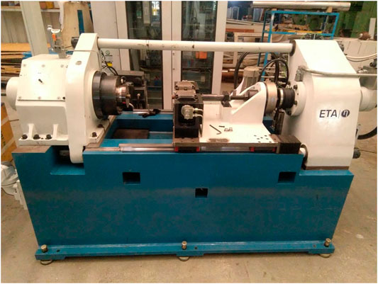
FIGURE 1. Rotary friction welding machine used in the current study.
The welding parameters that could be controlled in the present machine are listed in Table 2. For the welding trials, it was decided to hold some of the parameters constant. In this manner, the number of trials to achieve a quality joint can be smaller. Few reports suggest spindle speed maintained at higher ranges produces stronger joints (Rafi et al., 2010; Jin et al., 2019), whereas upset time does not have much of an effect on the final weld quality. Hence, the spindle speed was maintained constant at 2000 RPM, and the upset time was set at 4 s. It was decided to hold upset pressure twice that of the friction pressure in each experiment. Along these lines, first two sets of welding trials were conducted, namely, “minimum” and “maximum.” For the “minimum” condition, we set friction pressure at 50 MPa and the burn-off length at 1 mm, whereas for the “maximum” condition, the friction pressure was maintained at 250 MPa and the burn-off length at 7 mm. The remaining parameters are as given in Table 2. Upon visual inspection of the flash and after conducting drop tests, it was decided that the “maximum” condition welds were better in qualitative terms. For the next and final stage of experiments, the magnitude of the “extreme” conditions was slightly reduced and frozen for all the subsequent welds (Table 2), which were eventually subjected to various characterizing methods in this work. From the foregoing strategy, it is evident that the final set of parameters chosen in this study are not the “optimum best.” Nevertheless, as the current study was aimed more toward understanding the weld behavior of nitinol, it was felt that a lack of an optimized parameter set should not impair the overall conclusions.

TABLE 2. Welding parameters.
A solution containing 40% HNO3 and 10% HF in 50% distilled water was used to etch the nitinol friction weld. The chemical compositions of the nitinol rods were analyzed by employing a LECO TCH 400 instrument (LECO Corporation, St. Joseph, MI, United States). The macrostructure of the friction welds at low magnification was observed using a Nikon SMZ745T stereomicroscope (Nikon Instruments Inc., New York, NY, United States). The microstructure and fracture surfaces of the weld specimens were examined under a TESCAN VEGA 3LMV scanning electron microscope (SEM, TESCAN United States, Warren-dale, PA, United States) using a secondary electron imaging mode. The phases present in the nitinol base metal and welds were examined by X-ray diffraction using PAN analytical, Malvern, United Kingdom, X’pert powder XRD. The phase transformation behavior of nitinol base metal and welds was studied using a differential scanning calorimetry (DSC) machine (DSC 404 Pegasus, NETZSCH-Gerätebau GmbH, Germany) at a heating/cooling rate of 10°C in a nitrogen atmosphere. Vickers hardness (MMT-X Matsuzawa, Akita Prefecture, Kawabetoshima, Japan) measurement across the welds was carried out using a diamond pyramid indenter under a load of 500 g for 15 s. Tensile tests were carried out according to the ASTM E8 standard on the nitinol base metal and friction welded samples using a servo-hydraulic testing machine (Instron, Norwood, MA, United States) at a constant displacement rate of 1 mm/min.
Results and Discussion
Base Metal Microstructure
The optical and SEM microstructure of the nitinol base metal are shown in Figures 2A,B, respectively. The microstructure consists of equiaxed grains with a B2 austenite phase, and the average grain size of the base metal was 50 ± 4 µm. Nitinol alloy exhibits the shape memory effect and superelasticity because of reversible martensitic transformation (Deng et al., 2020). The Ni content plays a significant role in altering the starting and finishing phase transformation temperatures. However, in the current study, the nitinol base metal showed equiaxed B2 austenite grains in which martensitic bands are observed. The surface stress and cold deformation during metallographic preparation would result in the formation of a martensitic structure on the austenite grain surface. Similar observations have been made by Tadayyon et al. (2018) in the as-received NiTi specimen. Martensite formation from austenite would result in slip and dislocation network formation to facilitate the volumetric change of the martensite. Also, martensite is formed preferentially during a cold deformation process to release the local stress fields (Fernandes et al., 2011; Birk et al., 2016). Figure 2C shows the EDS spectrum of the nitinol base metal. The compositional distribution of the nitinol base metal was found to be Ti 50.18 (at%) and Ni 49.82 (at%). There was a noticeable absence of carbon or oxygen.
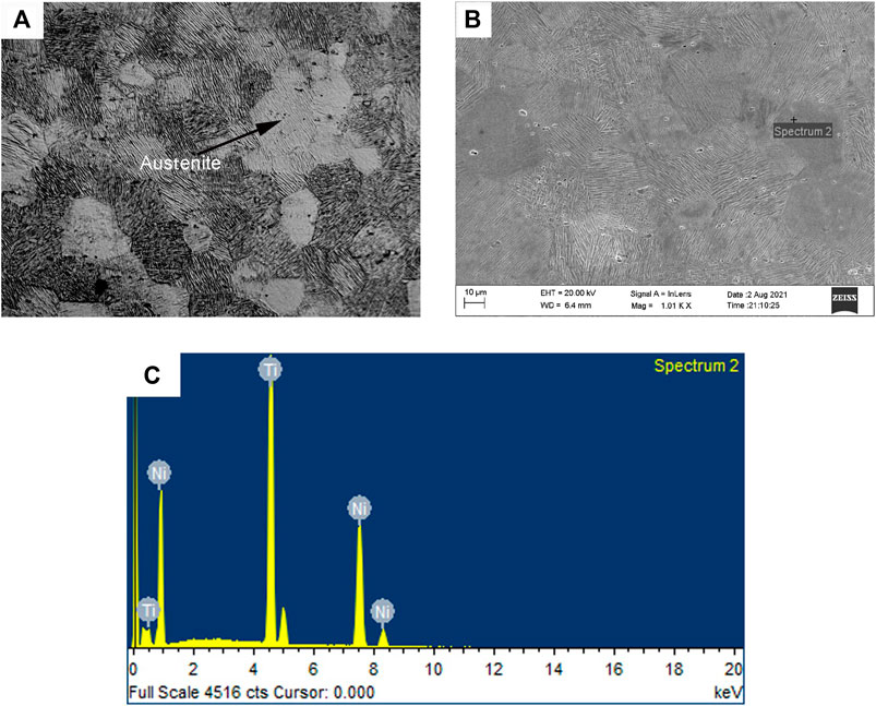
FIGURE 2. (A) Optical microstructure of nitinol base metal. (B) SEM microstructure of nitinol base metal. (C) EDS spectrum.
Macrostructure of Welds
Figure 3 shows a macro-view of the welded joint. The joint exhibits an equal and uniform flash around the circumference of the weld. The flash mainly consists of the oxidized film, which initially existed at the root of the weld and subsequently expelled during the rotary friction welding process. No macroscopic defects such as cracks and incomplete bonding were observed. The macroscopic transverse sectional view of the welds is shown in Figure 4. The joint exhibited a thin (120 µm) weld interface. A magnified view of the central region revealed recrystallized fine grains at the weld interface; deformed grains with flow lines are visible on either side adjacent to the weld interface. This highly deformed structure is referred to as the thermomechanically affected zone (TMAZ). In TMAZ, the base metal grains were seen elongated in an upward flowing pattern around the weld interface. Recrystallization is often negligible in this zone because of insufficient strains.

FIGURE 3. Visual view of a nitinol–nitinol friction welded joint.
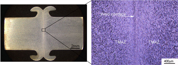
FIGURE 4. Friction welded nitinol sample showing the equal and uniform flash around the circumference of the weld.
Microstructure of Welds
Figure 5A shows a friction weld cross section comparing the weld interface, TMAZ, heat-affected zone (HAZ), and base metal. Severe plastic deformation and frictional heat generated between a rotating working piece and a stationary workpiece during rotary friction welding results in the generation of fine recrystallized grains at the weld interface due to dynamic recrystallization. There is a clear distinction between TMAZ and HAZ. Similar observations have been reported by Shinoda et al. (1992), Shinoda et al. (1999). The average grain size of the weld was 15 ± 3 µm. Severe plastic deformation and thermal cycles during friction welding impart strain energy into the material due to the increase in the density of defects. Recrystallization is the process of reducing the free energy of the system, which is influenced by important factors like initial grain size, thermomechanical processing route, chemical composition, second phase particles, and stacking fault energy (Huang and Logé, 2016). Dynamic recrystallization is a phenomenon that causes thermomechanically processed materials to develop very fine grains. The material experiences a significant amount of plastic deformation throughout the friction welding process. The grains are fractured, and many low-angle misoriented grain boundaries are formed during plastic deformation; moreover, highly favorable sites for the nucleation of recrystallized grains are created (Feng and Ma, 2009). The growth of the nuclei at the expense of deformed grains eventually results in a microstructure with fine equiaxed grains.
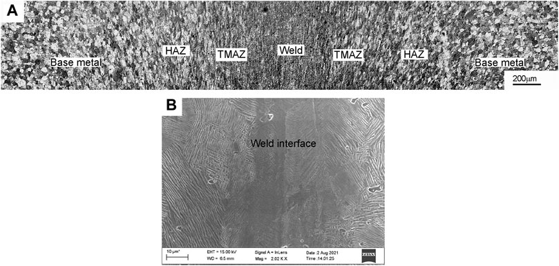
FIGURE 5. (A) Friction weld cross section when compared with the weld interface, TMAZ and heat-affected zone (HAZ), and base metal. (B) SEM microstructure of the nitinol weld interface at high magnification.
It is worth noting that continuous dynamic recrystallization occurs in metals with high stacking fault energy, like nitinol, subjected to a temperature greater than 50% of the melting point (Mani Prabu et al., 2017; Mani Prabu et al., 2019). The material subjected to rotary friction welding does not melt during welding but induces welding temperatures up to 0.7–0.8 of the melting point at the weld interface (Mary and Jahazi, 2008), which produces new nucleation sites, resulting in a decrease in grain size. Hence, fine recrystallized grains were observed at the weld interface during rotary friction welding of nitinol alloys. The region next to the weld interface experiences high temperature and lower strain, which results in the formation of the TMAZ consisting of deformed grains, unlike the recrystallized grains in the weld region. No significant grain coarsening was observed in the HAZ of the welded joint. The HAZ experiences a heating cycle and is subjected to plastic deformation. The grains in the HAZ remained almost like that of the base metal.
Figure 5B shows the microstructure of the weld and the adjacent regions seen at high magnification under SEM. The narrow recrystallized fine-grained zone was observed at the centerline of the weld. The width of this zone seems to lie in the range 20–30 µm. During the friction welding cycle, it can be suggested that the material was subjected to dynamic recrystallization followed by recovery, which eventually would result in the formation of fine-grained structure (Mani Prabu et al., 2019). The SEM micrograph showed martensitic bands inside the austenitic grains. This is evident in the SEM image, wherein finer martensitic needles are observed in the weld region than the adjacent ones. Because of the heavy deformation in the weld region, the chance of stress-induced martensitic formation is high (Fu et al., 2014). However, XRD patterns of the weld displayed diffraction peaks corresponding to the B2 austenitic phase, and no minor peaks from martensite were observed. As discussed earlier, like the base metal, it can be suggested that the martensite bands observed in SEM micrographs are the result of the cold deformation on the surface due to the stresses during the metallographic sample preparation.
XRD Analysis
Figure 6 illustrates the XRD analysis of the base metal and weld metal, where the austenitic (B2-cubic) and with minor traces of martensitic phase (B19′-monoclinic) were present. The most commonly observed intermetallic phases like NiTi2 and NiTi3 during fusion welding of nitinol alloys were absent in the rotary friction welding process. These observations are consistent with observations made by Prabu et al. (2019) during friction stir welding of nitinol alloy. Fortunately, the intermetallics observed in fusion welding detrimental for the shape memory effect were absent in the present study.
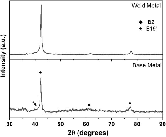
FIGURE 6. X-ray diffraction (XRD) profiles of the nitinol base metal and friction welds.
DSC Analysis
The DSC curves of the nitinol base metal and weld metal are shown in Figures 7A,B, respectively. As, Af, Ms, and Mf are denoted as austenite starting, austenite finishing, martensite starting, and martensite finishing temperatures, respectively. The DSC curves of the base metal exhibit exothermic phase transformation peaks from austenite to martensite (B2 →R → B19′) during cooling and reverse endothermic phase transformation from martensite to austenite (B19′→ B2) during heating, as shown in Figure 6A. Two-step austenite-to-martensite transformation, B2 →R and R → B19′, was observed during cooling, which led to an intermediate R phase formation. The R phase (rhombohedrally distorted form of the martensite) formed from austenite (B2) during cooling, as a precursor phase to the martensite (B19′) due to the lower activation barrier for the R phase formation from the B2 phase (Duerig and Bhattacharya, 2015). The transformation temperatures, both martensitic and austenitic, were shifted to higher temperatures for the weld metal when than the base metal, as shown in Figure 7B. It is important to note that the drift in phase transformation temperatures after rotary friction welding may be attributed to dislocation density, grain size, and residual stresses (Mani Prabu et al., 2017; Prabu et al., 2019). As already mentioned before, FW is a solid-state welding process that involves high temperatures and severe plastic deformation using frictional heat. The final grain size of weld, dislocation density, and residual stresses of weld depends upon the rotary friction welding parameters like frictional heat, upset pressure, and friction time. Furthermore, the direct B2 → B19′ transformation was observed during the cooling of the weld metal, without the intermediate R phase. This could be attributed to the presence of strain energy in the austenite phase of the weld metal, which could lower the activation barrier for the direct transformation to B19′. As suggested by Duerig and Bhattacharya (2015), B2 → R transformation involves lower transformation strains (0.2–0.5%) than the B2 → B19′ transformation (6–7%). Thus, B2 → B19′ transformation involves high activation barrier and often involves the formation of the intermediate R phase before the formation of the B19′ phase during cooling. Similar observations have been reported for nitinol–nitinol weldments prepared by the solid-state friction stir welding process (Prabu et al., 2019).
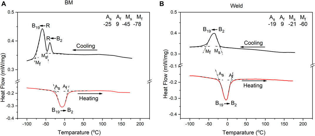
FIGURE 7. DSC curves of (A) nitinol base metal and (B) nitinol friction welded joint.
Mechanical Properties
Hardness
Figure 8 shows the hardness profiles across the midsection of nitinol–nitinol friction welded joints. The weld interface exhibited a higher hardness value (325 HV) than the base metal (306–312 HV) and TMAZ and HAZ (313–315 HV). This could be attributed to the fine recrystallized grains present at the weld interface due to heavy deformation followed by dynamic recrystallization. The base metal exhibits lower hardness values, and this could be the result of coarse equiaxed grains present in the microstructure. It is well known that fine grains at the weld interface contribute to high hardness according to the Hall–Petch equation; σy = σ0 + k/√8, where σy is the yield stress, σ0 is material constant for the resistance of the lattice to dislocation motion, k is the strengthening coefficient, and d is the average grain diameter (Bahador et al., 2019). A higher grain boundary area present at the weld interface acts as an obstacle to dislocation motion and thereby increases the hardness at the weld interface. On the other hand, the TMAZ of the weldment showed higher hardness than the nitinol base metal. Plastic deformation resulted in strain hardening and a consequent increase in dislocation density in the TMAZ region, which is adjacent to the weld interface. This higher dislocation density in the deformed grains of TMAZ leads to higher hardness values than the base metal. An increase in the hardness trend was observed after a transition from the base metal to the HAZ/TMAZ/weld interface.
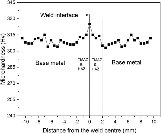
FIGURE 8. Hardness distribution across the interface of nitinol–nitinol friction welds.
Tensile Properties
Figure 9 shows the tensile curves of the base metal and friction welds. The friction welded sample exhibited higher yield strength (716 ± 6 MPa) and lower ultimate tensile strength (807 ± 8 MPa) and elongation (7 ± 0.5%) values than a base metal (yield strength of 585 ± 6 MPa, ultimate tensile strength of 918 ± 9 MPa, and % elongation of 15 ± 1). The high yield strength of the weld metal could be attributed to fine recrystallized grains present at the weld interface. Fine grains also contribute to higher strength and hardness, according to the Hall–Petch relationship. This result supports the findings of Prabu et al. (2019). It is important to note that solid-state welding techniques (friction welding and friction stir welding) exhibited higher yield strength (compared with the base metal) than fusion welding techniques like a laser beam, electron beam, and gas tungsten arc welding (Yang et al., 2014; Zoeram et al., 2017). On the other hand, the ultimate tensile strength of the weld mainly depends upon the bond strength at the weld interface and the weakest portion across the gauge portion. The gauge portion of a friction welded specimen contains the weld interface, TMAZ, HAZ, and base metal; the transition zone from refined grains at the weld interface to coarse grains at the HAZ acts as the weakest point for the fracture to occur. All friction welded samples failed at the HAZ. The failure location of the tensile specimen corresponding to nitinol–nitinol friction weld is shown in Figure 10. The tensile fracture surfaces of the nitinol base metal and welded samples are shown in Figures 11A,B. The base metal revealed predominantly dimpled features formed by microvoid coalescence, a characteristic of ductile fracture (Cho et al., 2021). While the fractured surface of the weld surely showed dimples, they were few and far between. The surface was mostly dominated by relatively flat features, giving an appearance more of a quasi-cleavage type of fracture.
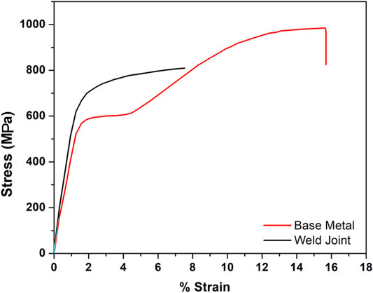
FIGURE 9. Tensile properties of the nitinol base metal and friction welds.

FIGURE 10. Failure location in a tensile specimen machined out of nitinol–nitinol friction weld.
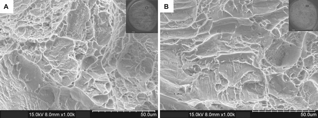
FIGURE 11. Fractured surfaces of (A) nitinol base metal and (B) nitinol friction welded joint.
Conclusion
The nitinol–nitinol similar welds produced using the rotary friction welding process have been analyzed for weld macro- and microstructures, grain size, and mechanical properties.
The following conclusions are drawn.
1) Rotary friction welding is a useful technique to join nitinol alloys that do not show significant fusion welding problems like cracks, incomplete bonding, and intermetallics.
2) The welded joint exhibits uniform flash throughout the circumference of the weld. Fine recrystallized grains were observed at the weld interface due to heavy deformation followed by dynamic recrystallization during rotary friction welding.
3) The drift in phase transformation temperatures after rotary friction welding may be attributed to fine grain size formation at the weld interface induced by thermomechanical processing.
4) The friction-welded nitinol–nitinol sample exhibited improved yield strength and hardness values when compared to the base metal due to grain refinement at the weld interface.
Data Availability Statement
The original contributions presented in the study are included in the article, further inquiries can be directed to the corresponding author.
Author Contributions
The study was conceptualized by AR, YU, and HK. Methodology was decided by AR, KB, MT, and YU. Formal analysis was done by AR, KB, MT, YU, and HK. Investigation of results was taken care of by AR, KB, MT, and YU. The original draft was written and reviewed by AR, KB, MT, YU, and HK.
Funding
This research was funded by the National Plan for Science, Technology and Innovation (MAARIFAH), King Abdulaziz City for Science and Technology, Kingdom of Saudi Arabia (Award Number 14-ADV110-02).
Conflict of Interest
The authors declare that the research was conducted in the absence of any commercial or financial relationships that could be construed as a potential conflict of interest.
Publisher’s Note
All claims expressed in this article are solely those of the authors and do not necessarily represent those of their affiliated organizations, or those of the publisher, the editors, and the reviewers. Any product that may be evaluated in this article, or claim that may be made by its manufacturer, is not guaranteed or endorsed by the publisher.
Acknowledgments
This Project was funded by the National Plan for Science, Technology and Innovation (MAARIFAH), King Abdulaziz City for Science and Technology, Kingdom of Saudi Arabia, Award Number (14-ADV110-02). The authors acknowledge Ashfaq Mohammad at the National Manufacturing Institute Scotland for his technical inputs during the experimental and writeup stages of the present work. The authors thank Ashfaq Mohammad at the National Manufacturing Institute Scotland for his technical inputs during the experimental and write-up stages of the present work. In addition we also would like to add Dr. Ashfaq for his kind help in manuscript preparation.
References
American Welding Society (2007). “Welding Handbook,” in Welding Processes, Part 2. 9 (Miami, Fla: American Welding Soc), Vol. 3.
Bahador, A., Umeda, J., Tsutsumi, S., Hamzah, E., Yusof, F., Fujii, H., et al. (2019). Asymmetric Local Strain, Microstructure and Superelasticity of Friction Stir Welded Nitinol alloy. Mater. Sci. Eng. A 767, 138344. doi:10.1016/j.msea.2019.138344
Birk, T., Biswas, S., Frenzel, J., and Eggeler, G. (2016). Twinning-Induced Elasticity in NiTi Shape Memory Alloys. Shap. Mem. Superelasticity 2, 145–159. doi:10.1007/s40830-016-0064-1
Cho, L., Bradley, P. E., Lauria, D. S., Martin, M. L., Connolly, M. J., Benzing, J. T., et al. (2021). Characteristics and Mechanisms of Hydrogen-Induced Quasi-Cleavage Fracture of Lath Martensitic Steel. Acta Materialia 206, 116635. doi:10.1016/j.actamat.2021.116635
Choi, E., Park, S.-H., Cho, B.-S., and Hui, D. (2013). Lateral Reinforcement of Welded SMA Rings for Reinforced concrete Columns. J. Alloys Compd. 577, S756–S759. doi:10.1016/j.jallcom.2012.02.135
Deepan Bharathi Kannan, T., Sahithya, P., and Ramesh, T. (2017). Experimental Investigation and Characterization of Laser Welded NiTinol Shape Memory Alloys. J. Manufacturing Process. 25, 253–261. doi:10.1016/j.jmapro.2016.12.006
Deepan Bharathi Kannan, T., Ramesh, T., and Sathiya, P. (2016). A Review of Similar and Dissimilar Micro-joining of Nitinol. JOM 68, 1227–1245. doi:10.1007/s11837-016-1836-y
Deng, H., Chen, Y., Li, S., Chen, C., Zhang, T., Xu, M., et al. (2020). Microstructure, Mechanical Properties and Transformation Behavior of Friction Stir Welded Ni50.7Ti49.3 alloy. Mater. Des. 189, 108491. doi:10.1016/j.matdes.2020.108491
Duerig, T. W., and Bhattacharya, K. (2015). The Influence of the R-Phase on the Superelastic Behavior of NiTi. Shap. Mem. Superelasticity 1, 153–161. doi:10.1007/s40830-015-0013-4
Feng, A. H., and Ma, Z. Y. (2009). Microstructural Evolution of Cast Mg–Al–Zn During Friction Stir Processing and Subsequent Aging. Acta Materialia 57 (14), 4248–4260. doi:10.1016/j.actamat.2009.05.022
Fernandes, D. J., Peres, R. V., Mendes, A. M., and Elias, C. N. (2011). Understanding the Shape-Memory Alloys Used in Orthodontics. ISRN Dentistry 2011, 1–6. doi:10.5402/2011/132408
Frenzel, J., George, E. P., Dlouhy, A., Somsen, C., Wagner, M. F.-X., and Eggeler, G. (2010). Influence of Ni on Martensitic Phase Transformations in NiTi Shape Memory Alloys. Acta Materialia 58, 3444–3458. doi:10.1016/j.actamat.2010.02.019
Frenzel, J., Wieczorek, A., Opahle, I., Maaß, B., Drautz, R., and Eggeler, G. (2015). On the Effect of Alloy Composition on Martensite Start Temperatures and Latent Heats in Ni-Ti-Based Shape Memory Alloys. Acta Materialia 90, 213–231. doi:10.1016/j.actamat.2015.02.029
Fu, C. H., Sealy, M. P., Guo, Y. B., and Wei, X. T. (2014). Austenite-Martensite Phase Transformation of Biomedical Nitinol by ball Burnishing. J. Mater. Process. Technol. 214 (12), 3122–3130. doi:10.1016/j.jmatprotec.2014.07.019
Huang, K., and Logé, R. E. (2016). A Review of Dynamic Recrystallization Phenomena in Metallic Materials. Mater. Des. 111, 548–574. doi:10.1016/j.matdes.2016.09.012
Jin, F., Li, J., Liu, P., Nan, X., Li, X., Xiong, J., et al. (2019). Friction Coefficient Model and Joint Formation in Rotary Friction Welding. J. Manufacturing Process. 46, 286–297. doi:10.1016/j.jmapro.2019.09.008
Kapoor, D. (2017). Nitinol for Medical Applications: A Brief Introduction to the Properties and Processing of Nickel Titanium Shape Memory Alloys and Their Use in Stents. Johnson Matthey Technol. Rev. 61, 66–76. doi:10.1595/205651317X694524
Lima, J. S., and Neto, A. C. W. (2017). Friction Stir Welding of Austenitic NiTi Shape Memory Alloys. Glob. J. Res. Eng. 17 (1), 1–3.
London, B., Fino, J., Pelton, A., Fuller, C., and Mahoney, M. (2005). “Friction Stir Processing of Nitinol,” in Friction Stir Welding and Processing III. Editors RS Mishra, MW Mahoney, TJ Lienert, and KV Jata (Orlando: TMS (The Minerals, Metals & Materials Society)), 67–74.
Mani Prabu, S. S., Madhu, H. C., Perugu, C. S., Akash, K., Ajay Kumar, P., Kailas, S. V., et al. (2017). Microstructure, Mechanical Properties and Shape Memory Behaviour of Friction Stir Welded Nitinol. Mater. Sci. Eng. A 693, 233–236. doi:10.1016/j.msea.2017.03.101
Mani Prabu, S. S., Perugu, C. S., Madhu, H. C., Ashutosh, J., Khan, S., Jayachandran, S., et al. (2019). Exploring the Functional and Corrosion Behavior of Friction Stir Welded NiTi Shape Memory alloy. J. Manufacturing Process. 47, 119–128. doi:10.1016/j.jmapro.2019.09.017
Mary, C., and Jahazi, M. (2008). Multi-Scale Analysis of IN-718 Microstructure Evolution During Linear Friction Welding. Adv. Eng. Mater. 10, 573–578. doi:10.1002/adem.200700361
Mirshekari, G. R., Saatchi, A., Kermanpur, A., and Sadrnezhaad, S. K. (2013). Laser Welding of NiTi Shape Memory alloy: Comparison of the Similar and Dissimilar Joints to AISI 304 Stainless Steel. Opt. Laser Technol. 54, 151–158. doi:10.1016/j.optlastec.2013.05.014
Oliveira, J. P., Barbosa, D., Fernandes, F. M. B., and Miranda, R. M. (2016). Tungsten Inert Gas (TIG) Welding of Ni-Rich NiTi Plates: Functional Behavior. Smart Mater. Struct. 25, 03LT01. doi:10.1088/0964-1726/25/3/03LT01
Padula, I. S. A., Benzing, J., and Asnani, V. M. (2019). Superelastic Tire. Available at: https://patents.google.com/patent/US10449804B1/en (Accessed June 16, 2021).
Prabu, S. S. M., Madhu, H. C., Perugu, C. S., Akash, K., Mithun, R., Kumar, P. A., et al. (2019). Shape Memory Effect, Temperature Distribution and Mechanical Properties of Friction Stir Welded Nitinol. J. Alloys Compd. 776, 334–345. doi:10.1016/j.jallcom.2018.10.200
Rafi, H. K., Ram, G. J., Phanikumar, G., and Rao, K. P. (2010). Microstructure and Tensile Properties of Friction Welded Aluminum Alloy AA7075-T6. Mater. Des. 31 (5), 2375–2380. doi:10.1016/j.matdes.2009.11.065
Rehman, A. U., Usmani, Y., Al-Samhan, A. M., and Anwar, S. (2021). Rotary Friction Welding of Inconel 718 to Inconel 600. Metals 11, 244. doi:10.3390/met11020244
Shinoda, T., Owa, T., and Magula, V. (1999). Microstructural Analysis of Friction Welded Joints in TiNi alloy. Welding Int. 13, 180–185. doi:10.1080/09507119909447361
Shinoda, T., Tsuchiya, T., and Takahashi, H. (1992). Friction Welding of Shape Memory alloy. Welding Int. 6, 20–25. doi:10.1080/09507119209548136
Shinoda, T., Tsuchiya, T., and Takahashi, H. (1991). Functional Characteristics of Friction Welded Near-Equiatomic TiNi Shape Memory Alloy. Trans. Jpn. Welding Soc. 22, 102–108.
Tadayyon, G., Guo, Y., Biggs, M. J. P., and Tofail, S. A. M. (2018). Deformation Behavior of Heat-Treated Ni-Rich NiTi Shape Memory Alloy. Am. J. Mater. Sci. Appl. 6 (2), 7–21.
Tam, B., Khan, M. I., and Zhou, Y. (2011). Mechanical and Functional Properties of Laser-Welded Ti-55.8 Wt Pct Ni Nitinol Wires. Metall. Mat Trans. A. 42, 2166–2175. doi:10.1007/s11661-011-0639-6
Yang, D., Jiang, H. C., Zhao, M. J., and Rong, L. J. (2014). Microstructure and Mechanical Behaviors of Electron Beam Welded NiTi Shape Memory Alloys. Mater. Des. 57, 21–25. doi:10.1016/j.matdes.2013.12.039
Zhou, X., Chen, Y., Huang, Y., Mao, Y., and Yu, Y. (2018). Effects of Niobium Addition on the Microstructure and Mechanical Properties of Laser-Welded Joints of NiTiNb and Ti6Al4V Alloys. J. Alloys Compd. 735, 2616–2624. doi:10.1016/j.jallcom.2017.11.307
Keywords: rotary friction welding, nitinol alloy, phase transformation, hardness, tensile properties
Citation: Rehman AU, Babu NK, Talari MK, Usmani YS and Al-Khalefah H (2021) Microstructure and Mechanical Property Correlation Between Rotary Friction Welded Nitinol–Nitinol Joints. Front. Mater. 8:726383. doi: 10.3389/fmats.2021.726383
Received: 16 June 2021; Accepted: 13 August 2021;
Published: 11 November 2021.
Edited by:
Xiangchen Meng, Harbin Institute of Technology, ChinaReviewed by:
Ravi Kumar B, National Metallurgical Laboratory (CSIR), IndiaYu Chen, Northeastern University, China
Copyright © 2021 Rehman, Babu, Talari, Usmani and Al-Khalefah. This is an open-access article distributed under the terms of the Creative Commons Attribution License (CC BY). The use, distribution or reproduction in other forums is permitted, provided the original author(s) and the copyright owner(s) are credited and that the original publication in this journal is cited, in accordance with accepted academic practice. No use, distribution or reproduction is permitted which does not comply with these terms.
*Correspondence: Ateekh Ur Rehman, YXJlaG1hbkBrc3UuZWR1LnNh