 Shun Hu Zhang
 Jia Lin Xin
 Li Zhi Che
- Shagang School of Iron and Steel, Soochow University, Suzhou, China
During the rolling process of thick plate, the nonlinear specific plastic power that derived from the non-linear Mises yield criterion is difficult to be integrated, which has restricted the establishment of a rolling force model. To solve this problem, a new yield criterion is firstly established, and then used to derive a linear specific plastic power. Meanwhile, a kinematically admissible velocity field whose horizontal velocity component obeys the Logistic function is proposed to describe the metal flow of the deformed plate. On these bases, the rolling energy items including the internal deformation power of the deformed body, friction power on the contact surface, and shear power on the entry and exit sections are integrated successively, and the rolling force model is established. It is proved that the model can predict the rolling force well when compared with the actual data of multicomponent alloys. Besides, the formula for predicting the outlet thickness is ultimately given upon this derived model, and a good agreement is also found between the predicted values and the actual ones, since the absolute errors between them are within 0.50 mm.
Highlights
• A linear specific plastic power is derived form a linear yield criterion, which can be used to solve the nonlinear integral problem.
• A velocity field that was constructed in the form Logistic function can describe the metal flow in the deformation zone well.
• A good prediction of outlet thickness can be obtained through the present rolling force model due to its high predictive accuracy.
Introduction
The yield behavior of a material can be described by a yield criterion. It is an important basis for judging whether a material undergoes plastic deformation, or taken as an mechanical equation that must be solved for obtaining the required force for material forming. So far, there are many yield criteria, which are generally expressed in the form of stresses. In 1864, Tresca proposed the maximum shear stress theory (Tresca, 1864), which provided a basic theoretical explanation for the yield characteristics of materials. In 1900, Mohr used the Coulomb’s formula of shearing strength for rock and soil to improve his own strength theory and published the Mohr-Coulomb criterion (Mohr, 1900). This criterion is indeed a modification of the Tresca’s theory, in which the maximum shear stress is no longer a constant, but a function of the normal stress in the same plane. In 1913, von Mises believed that if the secondary invariant of deviation stress reached a specific value, then the metal would turn from elastic deformation to plastic deformation (Mises, 1913; Mises, 1928). Based on this assumption, the Mises yield criterion was proposed. However, the mathematical form of this criterion is nonlinear, which is not convenient for the derivation of analytical solutions of material forming force, such as the rolling force. In 1951, Drucker and Prager (Drucker and Prager, 1952) added the influence of hydrostatic pressure to the Mises’ formula, and the yield surface is shown to be a conical surface. Yu et al. (Yu, 2002) established the twin shear stress (TSS) yield criterion in 1961, and modified it in 1985 (Yu et al., 1985). The twin shear stress yield criterion assumes that when the sum of two larger principal shear stresses reaches a critical value, the material yields. This criterion is usually used to predict the upper limit of mechanical parameters. In 2005, Yu et al. (Gao and Yu, 2005) believed that although the TSS yield criterion can account for the influence of the intermediate principal stress, it neglected the influence of the minimum shear stress on the material yielding, and then they proposed the triple-shear stress yield criterion. In the case of combined shear stress on the element body, the three-shear yield criterion is more consistent with the actual results than the single-shear or twin shear yield criteria.
By summarizing the above information, it can be found that the Tresca yield criterion brings in a lower limit solution, the twin shear stress yield criterion brings in an upper limit solution. Although the nonlinear Mises yield criterion has high accuracy, it is difficult to obtain the analytical solution of material forming force. For this reason, it is necessary to find a new linear yield criterion whose locus can lies in between those based on the Tresca yield criterion and the twin shear stress yield criterion, and can approximate the Mises circle well, in order to meet the requirements of high accuracy and ease of calculation.
Thick plate is widely used in construction machinery, oil pipeline, offshore platform and other structural load-bearing part. How to accurately obtain the rolling force and rolling torque of thick plate is related to the selection of production parameters. The difficulty in solving the nonlinear Mises plastic power must be solved in the modeling of rolling force. In 2000, Wang et al. (Wang, 2000) used the three-dimensional stream function method to analyze the plastic processing problem, and established a flat roll rolling model considering the widening. Jia et al. (Jia et al., 2016) used the Zener-Hollomon parameter method to establish a flow stress model during unidirectional compression, and also established a flow stress model for variable temperature rolling. Liu (Liu, 2017) proposed a new exponential velocity field that can reflect the change law of metal flow for finishing rolling passes. Li et al. (Li and Wang, 1996) used the Hill yield criterion to study the stress field and velocity field of the plane stress problem of orthotropic materials, and obtained the result that the characteristic lines of the stress field and velocity field overlap everywhere. Zhang et al. (Zhang et al., 2019) proposed a new type of velocity field considering the rolling permeability to analyze the rolling of extra-thick plates. Their results show that the rolling force and rolling torque models considering the deformation penetration can give more accurate results. Based on the above researches, it can be found that the establishment of the velocity field by the analytical method can be used well in analyzing the problem of thick plate rolling, and is beneficial to the optimization of rolling parameters. However, the existing velocity fields with the above function form fail to accurately describe the vertical flow characteristic, which can arise big errors in predicting rolling force and torque. One important reason is that most of the available velocity fields can just satisfy the velocity boundary condition on the inlet section and neglect the required condition on the outlet section. In fact, a good velocity should satisfy the velocity boundary conditions on the inlet section and the outlet section simultaneously. Quantitative assessment is necessary for proposing a reasonable velocity field, which is desired to be done in the future.
In order to solve the above problems, i.e. the problem of integral difficulty of rolling power and the problem of inefficient accuracy of available models, this paper intends to develop a linear yield criterion that can approximate the nonlinear Mises yield criterion well, and bring in a linear specific plastic power to analyze the plate rolling process. For this purpose, a new velocity field in the form of Logistic function, that can satisfy the velocity boundary conditions rigorously, is also proposed for describing the thick plate rolling. Based on the new yield criterion and the new velocity field, the corresponding internal deformation power, friction power and shear power are obtained, and then the analytical rolling torque and force are obtained through the variational method. Meanwhile, the bouncing equation is given to predict the thickness of the rolled plate by embedding the rolling force model, and a comparison is carried out between the calculated ones and the experimental data.
Derivation of Average Slope Yield Criterion
Yield Criterion Expression
The locus of the Mises yield criterion is a circle on the
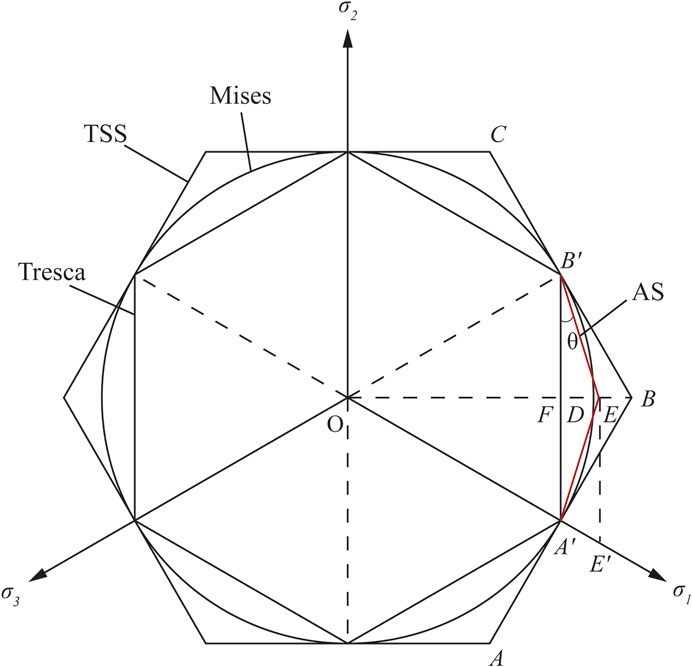
FIGURE 1. Different loci on the
In Figure 1, the radius of the Mises circle satisfies
Set the origin of the coordinate system at the point
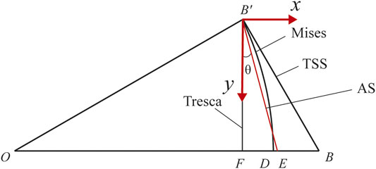
FIGURE 2. The geometry of the average slope yield criterion.
From the mean value theorem of integral (Zhang et al., 2020), the mean slope
Let
Based on the above formulas, we can get
The modulus length of the deviation vector on the Mises yield locus is
The modulus length of the deviation vector of the newly proposed yield criterion is
So, the error between them is
It can be seen that the vector modulus length of the newly proposed yield criterion is just a little higher than that of the Mises yield criterion, which means that the point E should be locates in between B and D, and near D, as shown in Figure 2.
The expressions of the lines
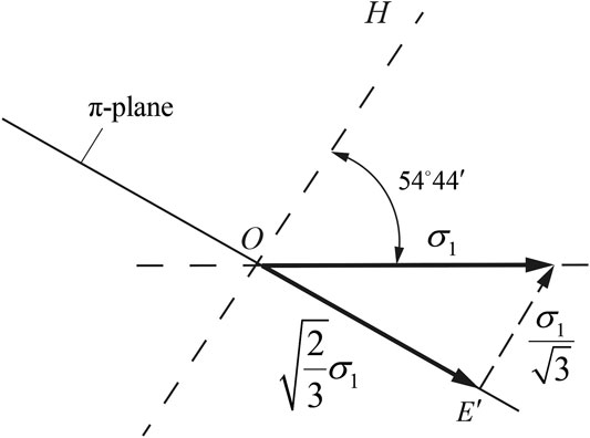
FIGURE 3. The locus of
It can be assumed here that the
When a material yields, there have
Substituting Eq. 11 into Eq. 10, the expression of
In the same way, the equation of the locus
Eqs 12, 13 are the mathematical expressions of the new yield criterion, which is a linear combination of the principal stress components. Because the slope of the locus side
It can be seen from Figure 2 that the present yield locus intersects the Mises circle, and the vertex angles are as follows:
Figure 1 and Eq. 14 show that the present yield locus is an equilateral and non-equiangular dodecagon which intersects the Mises circle with twelve intersection points. Of which, six vertices of the locus are on the Mises circle, and the vertex angle is
Specific Plastic Power
Suppose that the stress component
Assuming that there are
Similarly, according to Eqs 13, 15, it results in
The linear combination of the results obtained from the above two formulas gives
Take
Since
At the vertex E, we notice that
From Eqs 20, 21, the specific plastic power calculated by
By using the same method, the specific plastic power based on the Tresca yield criterion and the TSS yield criterion can be written as follows (Kobayashi et al., 1989)
Comparing Eq. 22 with Eqs 23, 24, the relative errors of the specific plastic power among the present one, the Tresca one, and the TSS one are
The relative errors in Eq. 25 indicate that the calculated value of using the mean slope yield criterion is
Experimental Validation
When the principal stress components satisfy
Substituting Eq. 26 into the Tresca criterion, Mises criterion, TSS yield criterion as well as the AS yield criterion, the following expressions in terms of the Lode characteristic parameter can be derived as follows:
Tresca:
Mises:
TSS:
AS:
Based on the above expressions, a comparison can be carried out with the experimental data from Ref. (Lode, 1926; Lessells and Macgregor, 1940; Naghdi et al., 1957; Maxey, 1974), shown in Figure 4.
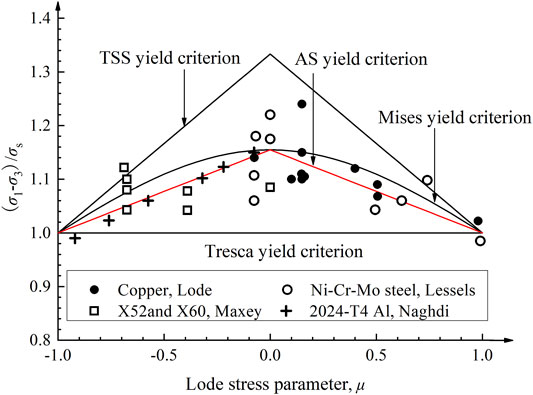
FIGURE 4. Comparison of various yield criteria and experimental data.
It can be seen from Figure 4 that the Tresca yield criterion predicts the lower bound of the experimental data, while the TSS yield criterion predicts the upper bound. The present calculated value is lie between those based on the TSS criterion and the Tresca criterion, and closes to that based on the Mises yield criterion. It can be seen that the predictive results based on the AS yield criterion correlate well with the experimental data, and can bring in the reasonable intermediate results since both the average error and the maximum error are very small, just 3.21 and 10.66% respectively.
Mechanical Analysis of Thick Plate Rolling
Velocity Field in the Form of Logistic Function
As shown in Figure 5,
where,
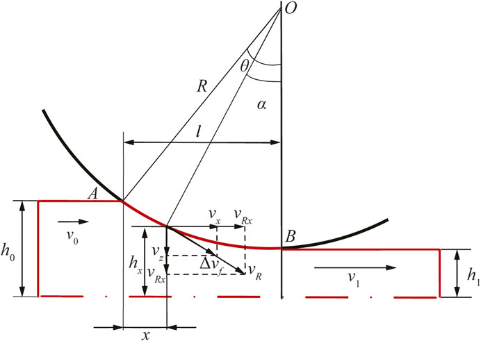
FIGURE 5. The thick plate in the rolling deformation zone.
From Eqs 31–34, the boundary conditions are as follows
where,
This article assumes that the horizontal velocity component
where,
According to the volume constant condition, i.e.
where,
where,
In Eqs 38, 39, due to
Internal Deformation Power
It is known that the specific plastic power based on the Mises yield criterion is nonlinear, which is difficult to be integrated to obtain the internal deformation power. For solving this problem, a new method called the replacement method of specific plastic power is proposed here. This method is to replace the specific plastic power of the Mises yield criterion by the present specific plastic power based on the AS yield criterion. Therefore, the internal deformation power
Friction Power
According to the roller surface equation
where,
From Figure 5, the direction cosines between
Substituting Eq. 45 into Eq. 44, we can get
where,
Shearing Power
From Eqs 35, 37, we can see that: on the exit section
Since there is no shear power consumed on the outlet section, the shear power
Total Power of Rolling Deformation and its Extreme Value
The total power
Therefore, by adding Eqs 41, 46, 48, it results in
From Eqs 40, 41, 46, 48, one can obtain that
Therefore, we can have
When the total power
Substituting a neutral angle
where, the arm coefficient
From the above derivation, it can be seen that the present new method of using a linear yield criterion to analyze a new velocity field can solve the problem of integral difficulty due to the nonlinear Mises yield criterion and can provide the possibility of acquiring an analytical model of rolling force for multi-component alloys. It also can be seen that such a model has a clear functional relationship, which is convenient to be used on-line in the process parameter design and the thickness control of a rolled plate.
Experimental Validation of Rolling Force and Thickness Prediction
An on-site rolling experiment was carried out in a domestic factory. The roller diameter is 1120mm, and the billet size is 320 mm × 2050 mm × 3250 mm. The measured rolling velocities for the 2nd–6th passes are 1.64, 1.66, 1.68, 1.82, and 1.97 m/s respectively. The arm coefficient
where,
The rolling torque and rolling force for the above passes can be predicted by Eq. 57, which is shown in Table 1.

TABLE 1. Validation of the predictive models of rolling force and torque with measured data.
In Table 1,
At the same time, the rolling force model obeys the bounce equation (Sun et al., 2013)
where,
Based on Eq. 59, the comparison between the predicted value of outlet thickness and the measured value for each pass can be shown in Table 2.
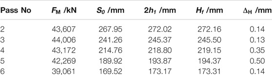
TABLE 2. Comparison of the predicted outlet thickness with the measured one.
In Table 2,
Analysis and Discussion
Figure 6 shows the effect of friction factor m and relative reduction
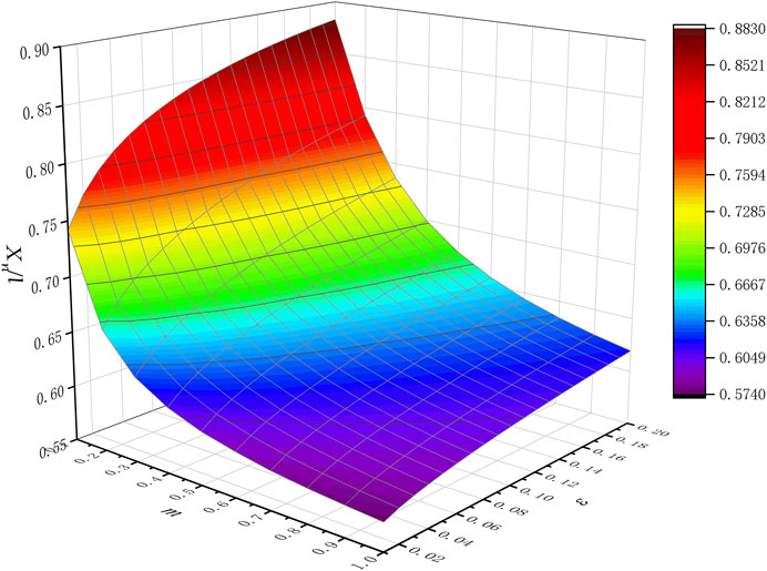
FIGURE 6. Effect of friction factor and relative reduction on the neutral point position.
Figure 7 shows the effect of shape factor
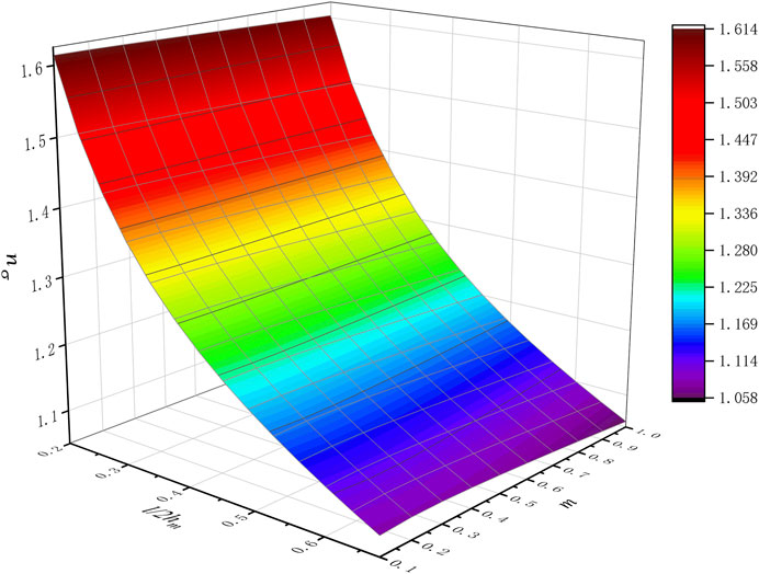
FIGURE 7. Effect of the shape factor and friction factor on the stress state coefficient.
Figure 8 shows the effect of the thickness-radius ratio
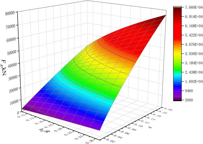
FIGURE 8. Effect of the thickness to radius ratio and relative reduction on the rolling force.
From the above comparison and analysis, it should be noted here that by comparing with the previous method, the present method of using a new yield criterion to analyze the present velocity field can not only provide an analytical solution of rolling force rather than a numerical one, but also can give more reasonable results with high precision (within 15%). This is due to the effectiveness of approximating to the Mises yield criterion with the present linear one and the rationality of proposing the present velocity field in the form of logistic function. In a word, the present paper has proposed a new method of analyzing the plate rolling process for multi component alloys. Based on this superiority, the process parameters of plate rolling can be designed and the thickness of the rolled plate can be controlled well, and the changing tendency of the rolling force along with many process parameters, such as the reduction, friction factor, thickness-to-radius ratio, can be disclosed quantitatively.
Conclusion
1) The AS yield criterion proposed in this paper is a linear combination of principal stress components. Its yield locus is an equilateral and non-equiangular dodecagon with side length of
2) This paper establishes a new velocity field based on the logistic function. This velocity field is proved to be satisfy the kinematically admissible condition rigorously. Based on the velocity field, the analytical solutions of rolling force and torque are established. After comparing with the measured rolling data, it is found that the analytical ones are in good agreement with the actual measured ones. The maximum errors for the rolling force and torque are 12.8 and 12.5% respectively. Besides, the bounce equation that based on the rolling force model is also given, and it is found that the predictive error is maintained at 0.25 mm, and the maximum error is no more than 0.50 mm. It can be seen that the method of using the AS yield criterion to analyze the proposed velocity field in this paper is effective.
3) It is found that as the friction factor m increases, the neutral point moves toward the inlet. As the reduction rate
Data Availability Statement
The original contributions presented in the study are included in the article/Supplementary Material, further inquiries can be directed to the corresponding author.
Author Contributions
SHZ: Responsible for modeling of rolling force; JLX: Responsible for collection of experimental data and model validation; LZC: Responsible for grammar modification.
Funding
This work is funded by the National Natural Science Foundation of China (Grant No. 52074187, U1960105, 51504156) and the Natural Science Foundation of Jiangsu Province (Grant No. BK20180095).
Conflict of Interest
The authors declare that the research was conducted in the absence of any commercial or financial relationships that could be construed as a potential conflict of interest.
Publisher’s Note
All claims expressed in this article are solely those of the authors and do not necessarily represent those of their affiliated organizations, or those of the publisher, the editors and the reviewers. Any product that may be evaluated in this article, or claim that may be made by its manufacturer, is not guaranteed or endorsed by the publisher.
References
Drucker, D. C., and Prager, W. (1952). Soil Mechanics and Plastic Analysis or Limit Design. Quart. Appl. Math. 10 (2), 157–165. doi:10.1090/qam/48291
Gao, J. P., and Yu, M. H. (2005). Study on the Unified Yield Criterion of Three-Shear Stress [J]. J. Xi’an Univ. Architecture Technol. Nat. Sci. Edition 37 (4). doi:10.15986/j.1006-7930.2005.04.019
Harris, J. N. (2014). Mechanical Working of Metals: Theory and practice[M], Vol. 36. Oxford: Elsevier.
Hosford, W. F., and Caddell, R. M. (2011). Metal Forming: Mechanics and metallurgy[M]. New York: Cambridge University Press.
Jia, W. T., Ma, L. F., and Ma, Z. Y. (2016). As-cast Rolling Process and Flow Stress of AZ31B Magnesium Alloy[J]. Rare Metal Mater. Eng. (1), 152–158.
Kobayashi, S., Kobayashi, S., and Oh, S. I. (1989). Metal Forming and the Finite-Element method[M]. Oxford: Oxford University Press on Demand.
Lessells, J. M., and Macgregor, C. W. (1940). Combined Stress Experiments on a Nickel-Chrome-Molybdenum Steel. J. Franklin Inst. 230 (2), 163–181. doi:10.1016/s0016-0032(40)90729-3
Li, S., Wang, Z., Liu, C., Ruan, J., and Xu, Z. (2017). A Simplified Method to Calculate the Rolling Force in Hot Rolling[J]. Int. J. Adv. Manufacturing Tech. 88 (5-8), 2053–2059. doi:10.1007/s00170-016-8890-z
Li, T., and Wang, Z. W. (1996). Characteristic Field of Plane Stress Problem for the Orthotropic Materials[J]. J. Harbin Inst. Tech. (04), 123–126.
Liu, Y. M. (2017). Research on Mathematical Model of Strip Rolling Force and Shape Control Based on Energy Method [D]. Shenyang: Northeastern University.
Lode, W. (1926). Versuche über den Einfluß der mittleren Hauptspannung auf das Fließen der Metalle Eisen, Kupfer und Nickel[J]. Z. für Physik A Hadrons Nuclei 36 (11), 913–939. doi:10.1007/bf01400222
Maxey, W. A. (1974). Measurement of Yield Strength in the Mill Expander[C]. Proc. fifth Symp. line pipe Res., 20–22.
Mises, R. V. (1913). Mechanik der festen Körper im plastisch-deformablen Zustand[J]. Nachrichten von der Gesellschaft der Wissenschaften zu Göttingen. Mathematisch-Physikalische Klasse 1913 (4), 582–592.
Mises, R. V. (1928). Mechanik der plastischen Formänderung von Kristallen. Z. Angew. Math. Mech. 8 (3), 161–185. doi:10.1002/zamm.19280080302
Mohr, O. (1900). Welche Umstände bedingen die Elastizitätsgrenze und den Bruch eines Materials[J]. Z. des Vereins Deutscher Ingenieure 46 (1524-1530), 1572–1577.
Naghdi, P. M., Essenburg, F., and Koff, W. (1957). An Experimental Study of Initial and Subsequent Yield Surfaces in plasticity[J]. New York: Mechanics Reviews, 201–209.
Sezek, S., Aksakal, B., and Can, Y. (2008). Analysis of Cold and Hot Plate Rolling Using Dual Stream Functions. Mater. Des. 29 (3), 584–596. doi:10.1016/j.matdes.2007.03.005
Sun, J., Peng, Y., and Liu, H. (2013). Coupled Dynamic Modeling of Rolls Model and Metal Model for Four High Mill Based on Strip crown Control. Chin. J. Mech. Eng. 26 (1), 144–150. doi:10.3901/cjme.2013.01.144
Tresca, H. (1864). Memoir on the Flow of Solid Bodies under strong Pressure[J]. Comptes-rendus de l’académie des Sci. 59, 754–758.
Wang, Z. F. (2000). Application of 3D Fluxional Function to Metal Forming [J]. J. Harbin Inst. Tech. (05), 93–96.
Wang, Z., Zhang, D., Gong, D., and Peng, W. (2019). A New Data-Driven Roll Force and Roll Torque Model Based on FEM and Hybrid PSO-ELM for Hot Strip Rolling. ISIJ Int. 59 (9), 1604–1613. doi:10.2355/isijinternational.isijint-2018-846
Yu, M. H., He, L. N., and Song, L. Y. (1985). Twin Shear Stress Theory and its Generalization[J]. Sci. China Ser. A-Mathematics, Phys. Astron. Technol. Sci. 28 (11), 1174–1183.
Yu, M.-h. (2002). Advances in Strength Theories for Materials under Complex Stress State in the 20th century. Appl. Mech. Rev. 55 (3), 169–218. doi:10.1115/1.1472455
Zhang, S. H. (2018). Linearization of Yield Criterion and its Engineering applications[M]. Beijing: Metallurgical Industry Press.
Zhang, S. H., Deng, L., Zhang, Q. Y., Li, Q. H., and Hou, J. X. (2019). Modeling of Rolling Force of Ultra-heavy Plate Considering the Influence of Deformation Penetration Coefficient. Int. J. Mech. Sci. 159, 373–381. doi:10.1016/j.ijmecsci.2019.05.048
Zhang, S. H., Gao, S. W., Wu, G. J., Cao, J., and Zhao, D. W. (2017). A Weighted Average Yield Criterion and its Applications to Burst Failure of Pipeline and Three-Dimensional Forging. J. Manufacturing Process. 28, 243–252. doi:10.1016/j.jmapro.2017.06.006
Keywords: rolling force, yield criterion, specific plastic power, thickness prediction, multicomponent alloys
Citation: Zhang SH, Xin JL and Che LZ (2021) Modeling of Rolling Force for Thick Plate of Multicomponent Alloys and Its Application on Thickness Prediction. Front. Mater. 8:741144. doi: 10.3389/fmats.2021.741144
Received: 14 July 2021; Accepted: 08 September 2021;
Published: 20 September 2021.
Edited by:
Shuozhi Xu, University of California, Santa Barbara, United StatesReviewed by:
Yifei Zeng, ExxonMobil, United StatesAkshay Dandekar, Stress Engineering Services, Inc., United States
Copyright © 2021 Zhang, Xin and Che. This is an open-access article distributed under the terms of the Creative Commons Attribution License (CC BY). The use, distribution or reproduction in other forums is permitted, provided the original author(s) and the copyright owner(s) are credited and that the original publication in this journal is cited, in accordance with accepted academic practice. No use, distribution or reproduction is permitted which does not comply with these terms.
*Correspondence: Shun Hu Zhang, c2h6aGFuZ0BzdWRhLmVkdS5jbg==