 Xudan Yao
 Ian A. Kinloch
 Mark A. Bissett
- Department of Materials, Henry Royce Institute and National Graphene Institute, University of Manchester, Manchester, United Kingdom
Glass fiber reinforced polymer (GFRP) composites are promising alternatives for the traditional carbon steel pipes used in the oil and gas industry due to their corrosion and chemical resistance. However, the out-of-plane mechanical properties of GFRPs still need further improvement to achieve this goal. Hence, in this work, two methods combining either vacuum mixing or spray coating with vacuum-assisted resin infusion were studied to fabricate graphene nanoplatelet (GNP)/GFRP hybrid composites. The former method resulted in a severe filtering effect, where the GNPs were not evenly distributed throughout the final composite, whereas the latter process resulted in a uniform GNP distribution on the glass fabrics. The addition of GNPs showed no modest contribution to the tensile performance of the GFRP composites due to the relatively high volume and in-plane alignment of the glass fibers. However, the GNPs did improve the flexural properties of GFRP with an optimal loading of 0.15 wt% GNPs, resulting in flexural strength and modulus increases of 6.8 and 1.6%, respectively. This work indicates how GNPs can be advantageous for out-of-plane mechanical reinforcement in fiber-reinforced composites.
Introduction
Glass fiber reinforced polymer (GFRP) composite has been increasingly investigated as an alternative piping material to carbon steel for oil and gas industry applications, owing to its lightweight, high specific strength and stiffness, good chemical and thermal resistance, ease of transportation, installation, and minimal maintenance (Edwards, 1998; Rafiee, 2016; Al-Samhan et al., 2017). In particular, the recent requirement of moving the offshore oil and gas industry from shallow coast to “deep water” production (Hale et al., 2000) challenged the traditional steel tether design: larger platforms are needed to withstand high axial tension mechanics for works deeper than 1500 m. As a result, lightweight materials, such as nonmetallic composites, are urgently needed for “deep water” applications (Ochoa and Salama, 2005), as well as other applications in demanding environments.
The curvature and flexibility of these composite pipelines lead to flexural and bend stresses, trigging the failure of composite laminates (Omrani et al., 2015; Seretis et al., 2017). To improve the bending properties of the composites, nanomaterials have been introduced to strengthen the matrix and interface. Graphene and its derivatives have been extensively studied since its first isolation in 2004 (Novoselov et al., 2004) and widely applied into fiber-reinforced polymer composites (Kamar et al., 2015; Qin et al., 2015; Wang et al., 2016a; Wang et al., 2016b; Mahmood et al., 2016; Monfared Zanjani et al., 2016; Pathak et al., 2016; Du et al., 2017; Jiang et al., 2017; Kwon et al., 2017; Prusty et al., 2017; Wang et al., 2017; Zhang et al., 2017; Umer, 2018; Yao et al., 2018; Jena et al., 2020; Topkaya et al., 2020; Vigneshwaran et al., 2020; Turaka et al., 2021), owing to their outstanding mechanical, electrical, and thermal properties. In particular, graphene nanoplatelets (GNPs), which are comprised of 10s of graphene layers, can be mass-produced by various techniques, including ball-milling, chemical exfoliation, thermal exfoliation, etc. (Jang and Zhamu, 2008; Young et al., 2012; Cataldi et al., 2018).
To introduce nanomaterials into the composite laminates, two primary methods have been used based on the vacuum assisted resin infusion (VARI) (Kamar et al., 2015). One is initially mixing the nanomaterials with epoxy resin, followed by VARI; another is coating/sizing the fibers with nanomaterials, followed by VARI (Kamar et al., 2015). Seretis et al. (2017) previously mixed GNPs with epoxy resin by mechanical stirring, followed by a hand layup procedure. With increasing GNP content, the flexural strength of the composites increased initially and then reached a plateau, followed by a reduction with the GNP content increasing further (Seretis et al., 2017). Wang et al. (2016b) combined sonication, a calendaring technique, and high-speed shear mixing to combine GNPs with epoxy and then used a hand layup technique for composite preparation. The flexural strength of the GFRP composites increased initially, followed by a decrease with adding GNPs (Wang et al., 2016b). Eaton et al. (2014) plasma functionalized carbon nanofillers and then mixed them with resin by three roll mill, followed by resin infusion, claiming that it could be used to make the hybrid composites. Zhang et al. (2015, 2017) studied the filtration effect of GNPs during resin infusion of nano-engineered hierarchical composites and claimed that the effect is related to filler dimensions, fiber volume fractions, and flow length. In addition, a spray-coating method was proposed to avoid the potential filtration effect when introducing GNPs into composite laminates (Zhang et al., 2015; Zhang et al., 2017).
In this work, both methods combining either vacuum mixing or spray coating with VARI were studied for GNP/GFRP hybrid composite fabrication. Afterward, the latter was selected for preparing GFRP composites with various GNP loadings [0–5 wt% relative to the coated glass fabric (GF)], owing to its uniform distribution. Before the final pipeline applications, the effects of GNPs on GFRP composite panels were discussed in this work, with dry woven GF selected to simulate the structure of braided pipes. Tensile and four-point bending tests were performed on all samples, which verified the potential of spray-coating GNPs onto GF to improve the bending properties of GFRP composites.
Materials and Methods
Materials
The GNPs were purchased from First Graphene (UK) Ltd, with an average particle diameter of ∼10 µm and tapped density of 0.124 g cm−3. Plain weave woven GF, with an areal weight of 299 g m−2, was purchased from Easy Composites (UK). Low viscosity Araldite epoxy resin and Aradur hardener were purchased from Huntsman (United States). Ethanol was purchased from Fisher Scientific (United Kingdom).
Vacuum Mixing of GNP/Epoxy
To disperse the GNPs into the epoxy resin uniformly, high-speed vacuum mixing was applied using the SpeedMixer (DAC 600.2 CM51) under the conditions summarized in Table 1. GNPs were mixed initially with either epoxy resin or hardener, after which the other component was added. Scanning electron microscope (SEM) analysis of the brittle fracture surfaces was then undertaken to assess the GNP distribution and toughing mechanisms, as shown in Figure 1. All images show river lines caused by the brittle fracture of the thermoset resin (Hull, 1999; Olowojoba et al., 2017), with the crack deflection and pull-out contributed by the embedded GNPs (Johnsen et al., 2007; Bindu et al., 2014; Eqra et al., 2015; Domun et al., 2017; Hu et al., 2020), which are beneficial to the composite toughening. No difference was observed whether the GNPs were mixed into the resin or hardener first. Hence, as the weight ratio of the epoxy and hardener was 100:35, the GNPs were initially added to the epoxy for high-loading GNPs to be used.
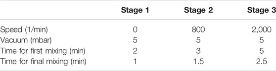
TABLE 1. Vacuum mixing parameters.
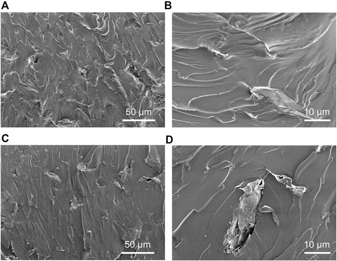
FIGURE 1. SEM images of fracture surfaces of (A, B) GNPs first mixed with epoxy resin followed by adding hardener and (C, D) GNPs first mixed with hardener followed by adding epoxy resin.
Filtering Effect
Once the epoxy–GNP formulation was prepared (Figure 2A), VARI was used to fabricate the composites (Figure 2B), followed by the cure cycle suggested by the supplier (80°C 2 h +140°C 8 h). After demoulding, it was visually observed that few GNPs had penetrated into the laminate, with most of them being filtered and remaining in the infusion mesh. This severe degree of filtering in the mesh suggests that the direct VARI method is not suitable for the GNP-loaded epoxy (Figure 2C).
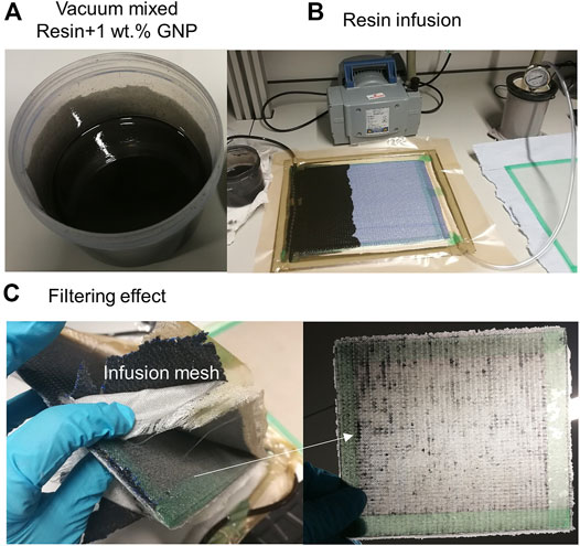
FIGURE 2. (A) Vacuum mixed epoxy resin with 1 wt% GNP, (B) vacuum-assisted resin infusion procedure, and (C) cured panel with a large amount of GNPs filtered and left in infusion mesh, rather than penetrate into glass fiber composites.
Spray Coating
To solve the GNP distribution problem, a spray-coating method was developed. Initially, GNPs were dispersed in ethanol, with the concentration of ∼5 mg ml−1, by ultra-sonication for 40 min. Eight layers of plain weave GF with a quasi-isotropic layup ([0/90]/[±45])2s were selected for the sample preparation. All internal surfaces were spray-coated with the dispersed GNPs (Figure 3A), using a Paasche VL airbrush system connected with an Iwata Power Jet Lite compressor. After being left overnight to evaporate all the solvent, the VARI method was used to fabricate the composites. Samples with the GF spray-coated with 0, 0.1, 0.5, 2, and 5 wt% of the GNPs (relative to the fabric) were prepared, where a 0 wt% sample was spray-coated with pure ethanol as a control to ensure this did not affect the mechanical properties of the fibers. Figures 3B, C represent the GF before and after the spray coating, where GNPs spread uniformly on the surface of the fabric. To check the final mass of GNPs, the fabric was weighed before and after the coating procedure, with the values summarized in Table 2. It suggests that there are weight losses caused by overspray and other mechanisms during the spray-coating procedure, and the final GNP loadings were found to be 0, 0.03, 0.15, 0.49, and 1.11 wt% relative to the fabric.
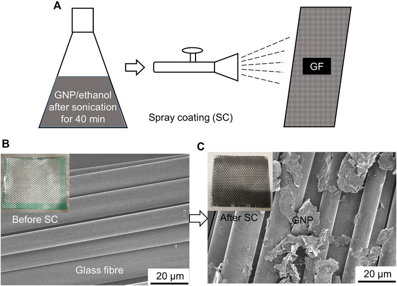
FIGURE 3. (A) Schematic of the spray-coating process. SEM images of glass fabric (B) before and (C) after spray-coated with GNPs. Embedded images are optical photos.
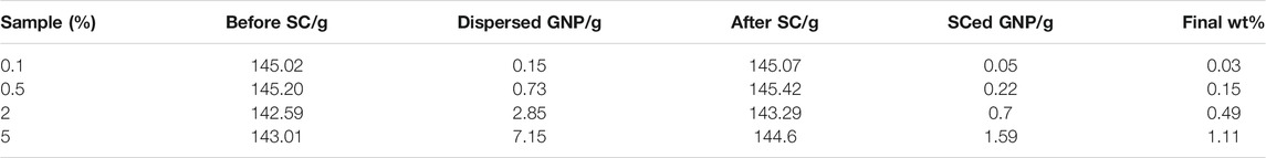
TABLE 2. Weight of glass fabric before and after spray coating (SC), GNP dispersed in ethanol and final amount spray-coated (SCed) onto fabric.
Characterization
Field emission SEM, SU5000, and TESCAN MIRA3 SC were used to observe the morphology of the GNPs, GF, and composites. An FEI Tecnai G2 20 (LaB6) transmission electron microscopy (TEM) was used to evaluate the GNPs using bright-field images and diffraction patterns. A Renishaw InVia Raman system was applied to obtain the Raman spectroscopy of the GNPs, using the 633-nm laser. A Thermo Scientific Nicolet iS50-IR with a diamond ATR crystal was used to conduct the Fourier transform infrared (FTIR) spectroscopy. The density of the composites was measured by a Sartorius YDK03 Density Kit through liquid buoyancy, using isopropyl alcohol as the liquid, based on the standard ASTM D792. A NETZSCH STA 449 F5 Jupiter was used for the thermogravimetry analysis.
Mechanical Testing
The mechanical performance of the composites was evaluated through tensile and four-point bending tests, each test with three specimens, according to ASTM D3039 and ASTM D7264 standards. The specimen sizes of 250
where L is the support span (mm), d is the depth (thickness) of the beam (mm), and Z is the straining rate of the outer fibers (0.01 mm/mm min).
Results and Discussion
Morphology and Structure
The representative Raman spectrum, SEM image, TEM image, and its selected area electron diffraction pattern of the GNPs used are shown in Figure 4. Characteristic G (∼1,581 cm−1), 2D (∼2,672 cm−1), and D (∼1,332 cm−1) bands of graphitic materials are shown in the Raman spectrum (Figure 4A). Here, the G band represents the C-C sp2 network (Lin et al., 2015), the broad and asymmetric 2D band suggests the GNP consists of graphene with many layers (Lin et al., 2015; Ferrari et al., 2006), and the D band indicates the structural defects related to the zone-boundary phonons (Ferrari et al., 2006). In addition, FTIR was used to identify functional groups of the GNP flakes. As shown in Figure 4B, the representative C=C stretching band (∼1,586 cm−1), hydroxyl band (C-OH, ∼1,200 cm−1), epoxy vibrational band (C-O-C, ∼1,107 cm−1), and carboxyl band (C=O, ∼1,700 cm−1) are clearly observed (Ţucureanu et al., 2016; Coates, 2006; Li et al., 2018; Li et al., 2013). The existence of these functional groups paves the path for improving interfacial connections through reacting with epoxy matrix. The SEM image and TEM bright-field image (Figures 4C, D) illustrate the GNP flake structure with the lateral size varies from a few to ∼15 microns. Figure 4E shows the corresponding selected area electron diffraction pattern of the GNP in Figure 4D. It indicates the crystalline structure of the GNP, which has many layers of graphene with highly ordered hexagonal arrangements of carbon atoms (Venturi and Hussain, 2020).
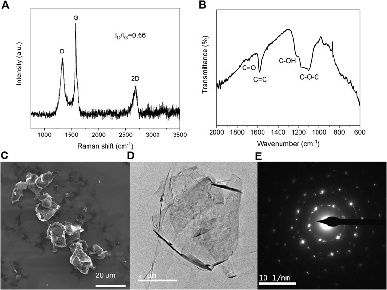
FIGURE 4. (A) Raman spectrum, (B) FTIR spectrum, (C) SEM image, (D) TEM bright field image and (E) corresponding selected area electron diffraction pattern of the GNP.
Figure 5 shows the SEM images of GFs spray-coated with 0.03, 0.15, 0.49, and 1.11 wt% GNPs. With the increasing loading, more and more GNPs are seen to be connected with each other and form continuous networks. The surface coverage of GNPs was assessed using ImageJ, and it was found that the GNP areal coverage increased from 7.2 to 22.6, 42.1, and 59.9% at 0.03, 0.15, 0.49, and 1.11 wt% GNPs, respectively. This may have significant effects on the interfacial connections and thus mechanical properties of the composites.
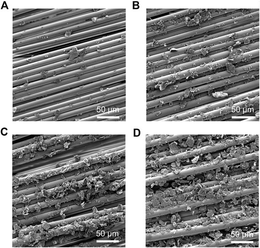
FIGURE 5. SEM images of glass fibres spray-coated with (A–D) 0.03, 0.15, 0.49, and 1.11 wt% GNPs.
Fibre Volume Fraction
To check the fiber volume fraction and void content of the composites, thermogravimetry analysis was used with nitrogen as the atmosphere and temperature ranging from room temperature to 800°C. The results are summarized in Figure 6, from which the weight percentage of the resin can be obtained as 34.7, 34.8, 35.6, 35, and 34% for control, 0.03, 0.15, 0.49, and 1.11% samples, respectively. The residual weight includes both glass fibers (GFs) and GNPs, which can be differentiated as mentioned in Section 2.4. Afterward, the fiber volume fraction (
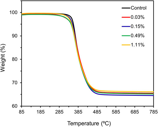
FIGURE 6. Thermogravimetric analysis for GFRP composites with different GNP loadings.
whereas the void content (
where ρ is the density, W is the weight fraction, and V is the volume fraction. The subscript symbols f, c, v, r, and g represent the glass fiber, composite, void, resin, and GNP, respecctively. The density of the composite was measured by a Sartorius YDK03 Density Kit, whereas densities of the fiber (2.54 g/cm3), GNP (2.2 g/cm3), and resin (1.19 g/cm3) are constant. All corresponding results are summarized in Table 3.
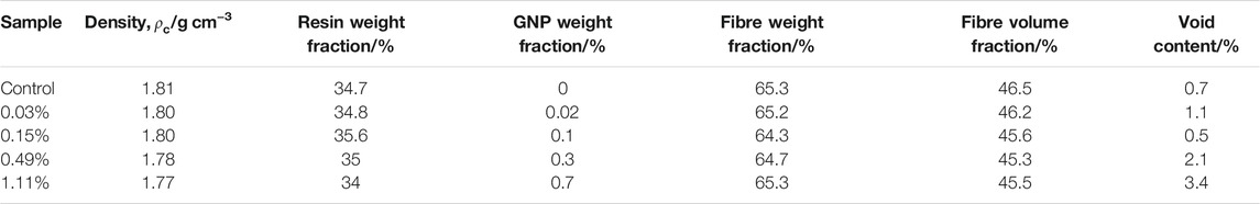
TABLE 3. Density, fiber weight/volume fraction, and void content of composites with different GNP loadings.
The results suggest that with the GNP loading increasing, the fiber volume fraction decreased gradually, and void content tends to increase, particularly at high GNP loadings (0.49 and 1.11%). This could be attributed to the 2D layered structure of the GNPs, which led to more voids trapped between the flakes.
Tensile Properties
The representative stress–strain curves of the composites with different GNP loadings under tension are shown in Figure 7A. The embedded photo of the samples indicates the uniform distribution of the GNPs. All composites exhibited linear behavior during the tensile tests. In particular, all curves overlapped at the initial stage (0–0.5% strain), where the tensile modulus was determined using the strain range between 0.1 and 0.3%. Hence, with the GNP loading increasing, the tensile modulus, which represents the elastic properties, remained unchanged with the values sitting within error bars, as shown in Figure 7B. However, with the strain further increasing, the curve of the sample with the highest GNP loading (1.11 wt%) separated with all other curves due to the formed continuous GNP networks (Figure 5D), which hindered the stress transfer and triggered the occurrence of the delamination (Kamar et al., 2015; Umer, 2018). As a result, the tensile strength, which is dominated by the fiber reinforcements rather than GNP fillers (Kumar et al., 2020), kept constant with the GNP addition until the loading reached 1.11 wt%, where the strength decreased by 12.9% (Figure 7B and Table 4).
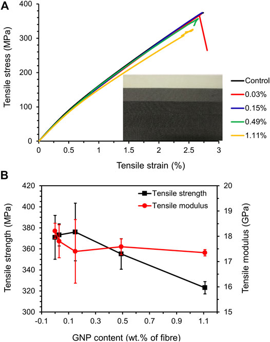
FIGURE 7. (A) Representative tensile stress–strain curves embedded with photos of samples with different GNP loadings. (B) Tensile strength and modulus of the composites.
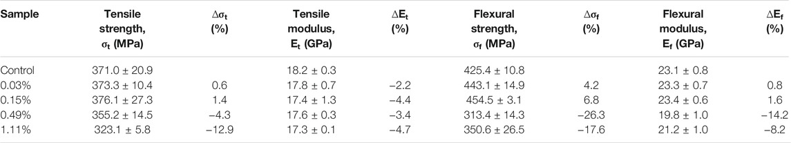
TABLE 4. Tensile and flexural properties of GFRP composites with different GNP loadings.
Flexural Properties
Compared with the tensile properties of the composites, which are governed by the reinforcing GF, flexural properties typically consist of a combination of the fabric, GNPs, matrix, and their interfacial connections (Wang et al., 2016b). Figure 8 shows the flexural stress–strain curves, strength, and modulus for all the composite laminates. All the curves showed linear behavior, indicating elastic deformation, with the slope increasing with loadings up to an optimum loading of 0.15 wt%, above which the properties began to decrease. Accordingly, the trend of both flexural strength and modulus (obtained from the 0.1 to 0.3% strain) initially increased, followed by a decrease with the GNP loading increasing. Both inflection points sit at 0.15 wt%, where the strength and modulus increased by 6.8 and 1.6%, respectively, as shown in Figure 8B and Table 4. This improvement was attributed to the strengthened interfacial connections, consisting of chemical bonding, mechanical anchoring, and interlocking, which can occur between the GNPs and matrix, which, as a result, prevented the crack initiation and increased the crack propagation path. Among them, the chemical bonding was contributed by the functional groups on the GNPs, such as hydroxyl, epoxy, and carboxyl, as evidenced by the FTIR (Figure 4B), which could interact more strongly with the epoxy matrix.
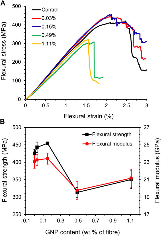
FIGURE 8. (A) Stress–strain curves of GFRP composites with different GNP loadings under four-point bending. (B) Flexural strength and modulus of the composites.
Other groups have also reported similar behaviors (Seretis et al., 2017; Wang et al., 2016b; Topkaya et al., 2020; Jena et al., 2020; Turaka et al., 2021); namely, the flexural properties got improved, followed by weakened with increasing GNP additions, as a small amount of GNPs could contribute to chemical bonding, mechanical anchoring, and interlocking between the interfaces (Pathak et al., 2016; Moaseri et al., 2014), which strengthened the composites under bending. However, the formation of GNP networks under high loadings (Figure 5D) accelerated the delamination and decreased the stress transfer efficiency (Kamar et al., 2015; Umer, 2018), thus weakening the composite performance.
Conclusion
This work studied two different methods for GNP/GFRP hybrid composite fabrication, firstly in which vacuum mixing was accompanied by direct VARI, resulting in a severe filtering effect of the GNPs. In comparison, spray coating of the GNPs onto the fiber surface followed by the VARI method of resin infusion resulted in a uniform GNP distribution in the composites. This process is flexible, allowing for a wide variety of shapes of the structure (e.g., pipes) to be achieved and can be applied onto any fibers and different fillers, which could also be easily scaled up for industrial applications.
With different GNP loadings applied, the tensile properties of the composite laminates, which are governed predominantly by the GFs, showed no obvious change until the loading increased up to 1.11 wt%. In contrast, the flexural properties were improved at low loadings of GNP (0.03 and 0.15 wt%), as a result of strengthened interfacial properties, and then weakened with the loading increased further (0.49 and 1.11 wt%) due to accelerated delamination and decreased stress transfer efficiency. In particular, with 0.15 wt% GNPs spray-coated onto the GF, flexural strength and modulus of the composite increased by 6.8 and 1.6%, respectively. Overall, the 0.15 wt% sample performed the best in this work, with the flexural properties being significantly improved. Understanding the mechanical properties of these GFRP materials is vital for many industrial applications where they would be expected to undergo flexural strain. In the future, different chemical functionalization could be applied to the fillers and matrix to strengthen the interfacial connection between the different constituent materials by chemical bonding and improve the mechanical performance further.
Data Availability Statement
The original contributions presented in the study are included in the article further inquiries can be directed to the corresponding authors.
Author Contributions
XY conducted the experiments and wrote the article draft, and MB and IK supervised the project. All authors contributed to the results discussion, analysis, and revision of the article.
Funding
This work was funded by PETRONAS in collaboration with the University of Manchester.
Conflict of Interest
This study received funding from PETRONAS. The funder had the following involvement with the study: decision to publish. All authors declare no other competing interests.
Publisher’s Note
All claims expressed in this article are solely those of the authors and do not necessarily represent those of their affiliated organizations or those of the publisher, the editors, and the reviewers. Any product that may be evaluated in this article, or claim that may be made by its manufacturer, is not guaranteed or endorsed by the publisher.
References
Al-Samhan, M., Al-Enezi, S., Al-Banna, A., and Yussuf, A. (2017). Effect of Crude Oil and Well Stream Chemical on Glass Fiber Epoxy Composite Pipes. Sci. Eng. Compos. Mater. 24 (6), 893–899. doi:10.1515/secm-2015-0183
Bindu, B. S., Nair, A. B., Abraham, B. T., Beegum, P. M. S., and Thachil, E. T. (2014). Microwave Exfoliated Reduced Graphene Oxide Epoxy Nanocomposites for High Performance Applications. Polymer 55 (16), 3614–3627. doi:10.1016/j.polymer.2014.05.032
Cataldi, P., Athanassiou, A., and Bayer, I. S. (2018). Graphene Nanoplatelets-Based Advanced Materials and Recent Progress in Sustainable Applications. Appl. Sci. 8 (9), 1438. doi:10.3390/app8091438
Coates, J. (2006). “Interpretation of Infrared Spectra, A Practical Approach,” in Encyclopedia of Analytical Chemistry, Chichester: John Wiley 8 Sons Ltd.1–23. doi:10.1002/9780470027318.a5606
Domun, N., Hadavinia, H., Zhang, T., Liaghat, G., Vahid, S., Spacie, C., et al. (2017). Improving the Fracture Toughness Properties of Epoxy Using Graphene Nanoplatelets at Low Filler Content. Nanocomposites 3 (3), 85–96. doi:10.1080/20550324.2017.1365414
Du, X., Zhou, H., Sun, W., Liu, H.-Y., Zhou, G., Zhou, H., et al. (2017). Graphene/epoxy Interleaves for Delamination Toughening and Monitoring of Crack Damage in Carbon Fibre/epoxy Composite Laminates. Composites Sci. Tech. 140, 123–133. doi:10.1016/j.compscitech.2016.12.028
Eaton, M. J., Ayre, W., Williams, M., Pullin, R., and Evans, S. L. (2014). “Nano-reinforcement of Resin Infused Carbon Fibre Laminates Reinforced Using Carbon Nano-Tubes and Graphene,” in 16th International Conference on Experimental Mechanics, Cambridge, United Kingdom, July 7, 2014, 1–3.
Edwards, K. L. (1998). An Overview of the Technology of Fibre-Reinforced Plastics for Design Purposes. Mater. Des. 19 (1–2), 1–10. doi:10.1016/s0261-3069(98)00007-7
Eqra, R., Janghorban, K., and Daneshmanesh, H. (2015). Mechanical Properties and Toughening Mechanisms of Epoxy/graphene Nanocomposites. J. Polym. Eng. 35 (3), 257–266. doi:10.1515/polyeng-2014-0134
Ferrari, A. C., Meyer, J. C., Scardaci, V., Casiraghi, C., Lazzeri, M., Mauri, F., et al. (2006). Raman Spectrum of Graphene and Graphene Layers. Phys. Rev. Lett. 97 (18), 187401–187404. doi:10.1103/PhysRevLett.97.187401
Hale, J. M., Shaw, B. A., Speake, S. D., and Gibson, A. G. (2000). High Temperature Failure Envelopes for Thermosetting Composite Pipes in Water. Plastics, Rubber and Composites 29 (10), 539–548. doi:10.1179/146580100101540752
Hu, B., Conghua, Y.-h., Zhang, B.-y., Zhang, L., Shen, Y., and Huangzhou, H.-z. (2020). Enhancement of Thermal and Mechanical Performances of Epoxy Nanocomposite Materials Based on Graphene Oxide Grafted by Liquid Crystalline Monomer with Schiff Base. J. Mater. Sci. 55 (8), 3712–3727. doi:10.1007/s10853-019-04273-2
Hull, D. (1999). Fractography: Observing, Measuring and Interpreting Fracture Surface Topography. Cambridge, UK: Cambridge University Press.
Jang, B. Z., and Zhamu, A. (2008). Processing of Nanographene Platelets (NGPs) and NGP Nanocomposites: A Review. J. Mater. Sci. 43 (15), 5092–5101. doi:10.1007/s10853-008-2755-2
Jena, A., Shubham, , Prusty, R. K., and Ray, B. C. (2020). Mechanical and Thermal Behaviour of Multi-Layer Graphene and Nanosilica Reinforced Glass Fiber/Epoxy Composites. Mater. Today Proc. 33, 5184–5189. doi:10.1016/j.matpr.2020.02.879
Jiang, J., Yao, X., Xu, C., Su, Y., Zhou, L., and Deng, C. (2017). Influence of Electrochemical Oxidation of Carbon Fiber on the Mechanical Properties of Carbon Fiber/graphene Oxide/epoxy Composites. Composites A: Appl. Sci. Manufacturing 95, 248–256. doi:10.1016/j.compositesa.2017.02.004
Johnsen, B. B., Kinloch, A. J., Mohammed, R. D., Taylor, A. C., and Sprenger, S. (2007). Toughening Mechanisms of Nanoparticle-Modified Epoxy Polymers. Polymer 48 (2), 530–541. doi:10.1016/j.polymer.2006.11.038
Kamar, N. T., Hossain, M. M., Khomenko, A., Haq, M., Drzal, L. T., and Loos, A. (2015). Interlaminar Reinforcement of Glass Fiber/epoxy Composites with Graphene Nanoplatelets. Composites Part A: Appl. Sci. Manufacturing 70, 82–92. doi:10.1016/j.compositesa.2014.12.010
Kumar, S., Singh, K. K., and Ramkumar, J. (2020). Comparative Study of the Influence of Graphene Nanoplatelets Filler on the Mechanical and Tribological Behavior of Glass Fabric‐reinforced Epoxy Composites. Polym. Composites 41 (12), 5403–5417. doi:10.1002/pc.25804
Kwon, Y. J., Kim, Y., Jeon, H., Cho, S., Lee, W., and Lee, J. U. (2017). Graphene/carbon Nanotube Hybrid as a Multi-Functional Interfacial Reinforcement for Carbon Fiber-Reinforced Composites. Composites B: Eng. 122, 23–30. doi:10.1016/j.compositesb.2017.04.005
Li, Z., Chu, J., Yang, C., Hao, S., Bissett, M. A., Kinloch, I. A., et al. (2018). Effect of Functional Groups on the Agglomeration of Graphene in Nanocomposites. Composites Sci. Tech. 163, 116–122. doi:10.1016/j.compscitech.2018.05.016
Li, Z., Young, R. J., Wang, R., Yang, F., Hao, L., Jiao, W., et al. (2013). The Role of Functional Groups on Graphene Oxide in Epoxy Nanocomposites. Polymer 54 (21), 5821–5829. doi:10.1016/j.polymer.2013.08.026
Lin, Y.-H., Yang, C.-Y., Lin, S.-F., and Lin, G.-R. (2015). Triturating Versatile Carbon Materials as Saturable Absorptive Nano Powders for Ultrafast Pulsating of Erbium-Doped Fiber Lasers. Opt. Mater. Express 5 (2), 236. doi:10.1364/ome.5.000236
Mahmood, H., Tripathi, M., Pugno, N., and Pegoretti, A. (2016). Enhancement of Interfacial Adhesion in Glass Fiber/epoxy Composites by Electrophoretic Deposition of Graphene Oxide on Glass Fibers. Composites Sci. Tech. 126, 149–157. doi:10.1016/j.compscitech.2016.02.016
Moaseri, E., Karimi, M., Maghrebi, M., and Baniadam, M. (2014). Fabrication of Multi-Walled Carbon Nanotube-Carbon Fiber Hybrid Material via Electrophoretic Deposition Followed by Pyrolysis Process. Composites Part A: Appl. Sci. Manufacturing 60, 8–14. doi:10.1016/j.compositesa.2014.01.009
Monfared Zanjani, J. S., Okan, B. S., Menceloglu, Y. Z., and Yildiz, M. (2016). Nano-engineered Design and Manufacturing of High-Performance Epoxy Matrix Composites with Carbon Fiber/selectively Integrated Graphene as Multi-Scale Reinforcements. RSC Adv. 6 (12), 9495–9506. doi:10.1039/c5ra23665g
Novoselov, K. S., Geim, A. K., Morozov, S. V., Jiang, D., Zhang, Y., Dubonos, S. V., et al. (2004). Electric Field Effect in Atomically Thin Carbon Films Supplementary. Science 5 (1), 1–12. doi:10.1126/science.1102896
Ochoa, O. O., and Salama, M. M. (2005). Offshore Composites: Transition Barriers to an Enabling Technology. Compos. Sci. Technol. 65 (15-16), 2588–2596. doi:10.1016/j.compscitech.2005.05.019
Olowojoba, G. B., Kopsidas, S., Eslava, S., Gutierrez, E. S., Kinloch, A. J., Mattevi, C., et al. (2017). A Facile Way to Produce Epoxy Nanocomposites Having Excellent Thermal Conductivity with Low Contents of Reduced Graphene Oxide. J. Mater. Sci. 52 (12), 7323–7344. doi:10.1007/s10853-017-0969-x
Omrani, E., Barari, B., Dorri Moghadam, A., Rohatgi, P. K., and Pillai, K. M. (2015). Mechanical and Tribological Properties of Self-Lubricating Bio-Based Carbon-Fabric Epoxy Composites Made Using Liquid Composite Molding. Tribology Int. 92, 222–232. doi:10.1016/j.triboint.2015.06.007
Pathak, A. K., Borah, M., Gupta, A., Yokozeki, T., and Dhakate, S. R. (2016). Improved Mechanical Properties of Carbon Fiber/graphene Oxide-Epoxy Hybrid Composites. Composites Sci. Tech. 135, 28–38. doi:10.1016/j.compscitech.2016.09.007
Prusty, R. K., Ghosh, S. K., Rathore, D. K., and Ray, B. C. (2017). Reinforcement Effect of Graphene Oxide in Glass Fibre/epoxy Composites at In-Situ Elevated Temperature Environments: An Emphasis on Graphene Oxide Content. Composites Part A: Appl. Sci. Manufacturing 95, 40–53. doi:10.1016/j.compositesa.2017.01.001
Qin, W., Vautard, F., Drzal, L. T., and Yu, J. (2015). Mechanical and Electrical Properties of Carbon Fiber Composites with Incorporation of Graphene Nanoplatelets at the Fiber-Matrix Interphase. Composites Part B: Eng. 69, 335–341. doi:10.1016/j.compositesb.2014.10.014
Rafiee, R. (2016). On the Mechanical Performance of Glass-Fibre-Reinforced Thermosetting-Resin Pipes: A Review. Compos. Structures 143, 151–164. doi:10.1016/j.compstruct.2016.02.037
Seretis, G. V., Kouzilos, G., Manolakos, D. E., and Provatidis, C. G. (2017). On the Graphene Nanoplatelets Reinforcement of Hand Lay-Up Glass Fabric/epoxy Laminated Composites. Composites Part B: Eng. 118, 26–32. doi:10.1016/j.compositesb.2017.03.015
Topkaya, T., Çelik, Y. H., and Kilickap, E. (2020). Mechanical Properties of Fiber/graphene Epoxy Hybrid Composites. J. Mech. Sci. Technol. 34 (11), 4589–4595. doi:10.1007/s12206-020-1016-4
Ţucureanu, V., Matei, A., and Avram, A. M. (2016). FTIR Spectroscopy for Carbon Family Study. Crit. Rev. Anal. Chem. 46 (6), 502–520. doi:10.1080/10408347.2016.1157013
Turaka, S., Reddy, K. V. K., Sahu, R. K., and Katiyar, J. K. (2021). Mechanical Properties of MWCNTs and Graphene Nanoparticles Modified Glass Fibre-Reinforced Polymer Nanocomposite. Bull. Mater. Sci. 44 (3), 194. doi:10.1007/s12034-021-02444-z
Umer, R. (2018). Manufacturing and Mechanical Properties of Graphene Coated Glass Fabric and Epoxy Composites. J. Compos. Sci. 2 (2), 17. doi:10.3390/jcs2020017
Venturi, F., and Hussain, T. (2020). Radial Injection in Suspension High Velocity Oxy-Fuel (S-HVOF) Thermal Spray of Graphene Nanoplatelets for Tribology. J. Therm. Spray Technol. 29 (1–2), 255–269. doi:10.1007/s11666-019-00957-y
Vigneshwaran, G. V., Shanmugavel, B. P., Paskaramoorthy, R., and Harish, S. (2020). Tensile, Impact, and Mode-I Behaviour of Glass Fiber-Reinforced Polymer Composite Modified by Graphene Nanoplatelets. Arch. Civ Mech. Eng. 20 (3). doi:10.1007/s43452-020-00099-x
Wang, C., Li, J., Sun, S., Li, X., Zhao, F., Jiang, B., et al. (2016). Electrophoretic Deposition of Graphene Oxide on Continuous Carbon Fibers for Reinforcement of Both Tensile and Interfacial Strength. Composites Sci. Tech. 135, 46–53. doi:10.1016/j.compscitech.2016.07.009
Wang, C., Li, J., Yu, J., Sun, S., Li, X., Xie, F., et al. (2017). Grafting of Size-Controlled Graphene Oxide Sheets Onto Carbon Fiber for Reinforcement of Carbon Fiber/epoxy Composite Interfacial Strength. Composites Part A: Appl. Sci. Manufacturing 101, 511–520. doi:10.1016/j.compositesa.2017.07.015
Wang, F., Drzal, L. T., Qin, Y., and Huang, Z. (2016). Size Effect of Graphene Nanoplatelets on the Morphology and Mechanical Behavior of Glass Fiber/epoxy Composites. J. Mater. Sci. 51 (7), 3337–3348. doi:10.1007/s10853-015-9649-x
Yao, X., Gao, X., Jiang, J., Xu, C., Deng, C., and Wang, J. (2018). Comparison of Carbon Nanotubes and Graphene Oxide Coated Carbon Fiber for Improving the Interfacial Properties of Carbon Fiber/epoxy Composites. Composites Part B: Eng. 132, 170–177. doi:10.1016/j.compositesb.2017.09.012
Young, R. J., Kinloch, I. A., Gong, L., and Novoselov, K. S. (2012). The Mechanics of Graphene Nanocomposites: A Review. Composites Sci. Tech. 72 (12), 1459–1476. doi:10.1016/j.compscitech.2012.05.005
Zhang, H., Liu, Y., Huo, S., Briscoe, J., Tu, W., Picot, O. T., et al. (2017). Filtration Effects of Graphene Nanoplatelets in Resin Infusion Processes: Problems and Possible Solutions. Composites Sci. Tech. 139, 138–145. doi:10.1016/j.compscitech.2016.12.020
Keywords: Graphene nanoplatelets, glass fiber composites, nanocomposites, mechanical properties, composite production
Citation: Yao X, Kinloch IA and Bissett MA (2021) Fabrication and Mechanical Performance of Graphene Nanoplatelet/Glass Fiber Reinforced Polymer Hybrid Composites. Front. Mater. 8:773343. doi: 10.3389/fmats.2021.773343
Received: 09 September 2021; Accepted: 20 October 2021;
Published: 16 November 2021.
Edited by:
Dong Xiang, Southwest Petroleum University, ChinaReviewed by:
Sandeep Kumar, University of Warwick, United KingdomJin Zhou, Xi’an Jiaotong University, China
Copyright © 2021 Yao, Kinloch and Bissett. This is an open-access article distributed under the terms of the Creative Commons Attribution License (CC BY). The use, distribution or reproduction in other forums is permitted, provided the original author(s) and the copyright owner(s) are credited and that the original publication in this journal is cited, in accordance with accepted academic practice. No use, distribution or reproduction is permitted which does not comply with these terms.
*Correspondence: Xudan Yao, eHVkYW4ueWFvQG1hbmNoZXN0ZXIuYWMudWs=; Mark A. Bissett, bWFyay5iaXNzZXR0QG1hbmNoZXN0ZXIuYWMudWs=