 Kai Guo1
 Chenghu Wang
- 1Transport Development Group Co, Ltd., of Henan Province, Zhengzhou, China
- 2Rioh Traffic Safety Co, Ltd., Beijing, China
It is crucial to examine the impact resistance of W-beam guardrails on both sides of the highway in order to limit the severity of impact incidents and safeguard passengers. Given its importance, this article investigates the impact resistance of the new three-wave steel guardrail. To be specific, the study uses ANSYS to establish the vehicle impact barrier model in which the guardrail is embedded in concrete and soil column. The new accurate model of the three-wave beam guardrail collision stimulates the deformation degree of the guardrail under the impact of vehicles with different masses and speeds. According to the simulation analysis’ findings, the guardrail with the post embedded in the concrete had a maximum displacement of 568.48 mm, which was less than the specification’s maximum dynamic deformation of 750 mm and met the requirements for Grade 8 protection. In contrast, the guardrail with the post embedded in the soil had a maximum displacement of 679.466 mm, which was less than the specification’s maximum dynamic deformation of 750 mm.
1 Introduction
1.1 Research background
Expressways provide convenience and enable fast traffic and transport, greatly speeding up people’s travel and playing a pivotal role in global transportation. China has accumulated high expressway mileage while the statistics are increasing. Meanwhile, the improving well-being of Chinese people has increased vehicle sales sharply in China, promoting the rapid development of the automobile industry. According to statistics, the number of cars in China reaches 205 million, which is continuously rising. More vehicles running on the road increase the possibility of accidents. Data show that in the first half of 2017, there were more than 8 million road traffic accidents in China. Among them, more than 200,000 accidents caused the casualties of more than 60,000 people, while injuries were even more. Behind the staggering data is the grief suffered by people at the loss of their beloved ones. The losses of assets and wealth are also numerous. As a key factor in expressway infrastructure, the performance of the guardrail is directly related to road safety. Therefore, improving the anti-impact performance of guardrails on both sides of the expressway is one of the main approaches to reducing the incidence of accidents, ensuring drivers’ and passengers’ safety, and improving the construction of expressway safety facilities.
The Ministry of the United States Transport began the study on safety vehicle tests in 1970 and summarized a safety performance evaluation assessing code on the guardrail. This code was added with more details and specific evaluations on the guardrail, including evaluation criteria on the impact speed, the impact angle, the standard of guardrail components, and the anti-impact performance of the guardrail. The Safety Evaluation Manual issued in 2009 is the latest and included the most detailed guardrail impact standards, replacing the codes in Report 350 (Nicol, 2009). According to the new manual, a dummy model would not be used in the future guardrail performance evaluation, while mini-cars and light trucks are adopted for the test. Also, listed out in the assessment standards are the mass and impact angle of testing vehicles (Jia et al., 2012). Japan began exploring guardrails after 1950. According to local road conditions and regulations, Japanese academics formulated a set of guardrail standards suitable for Japanese road traffic safety and made up the regulation in the 1960s. The regulation describes the design of guardrail components, the anti-impact performance of the guardrail, the code of use, and installation conditions and rules in detail, which shaped the widely accepted Japanese guardrail (Xie et al., 2003).
Some scholars have found that the impact height and grade of the guardrail on the slope are related to the vehicle’s driving track. The impact characteristics of four types of guardrails, including the modified W-beam guardrails, showed that the three-wave beam guardrail is the best choice for sloping roads. Priyanka Alluri et al. studied the anti-impact performance of the W-beam guardrail and arresting cable and compared their safety through the Z-test and the odds ratio, which turned out that the anti-impact performance of the W-beam guardrail was better. Most expressway guardrail structures applied in China are 3-mm W-shaped beams (Zheng, 2013). In addition to the impact resistance of the guardrail construction, experts have turned their attention to the impact resistance of other materials. Khan et al. (2019a) studied the 7055 spray-forming aluminum alloy and the conventionally formed 6061 aluminum and 7A52 aluminum alloys. Multiple measurements investigated the evolution of microstructure using an optical microscope (OM), scanning electron microscope (SEM), electron backscatter diffraction (EBSD), and X-ray diffraction (XRD). The research mainly observed the mechanical properties and damage modes of the single-layer aluminum alloy under the impact of a heavy tungsten alloy (WHA) projectile. During the impact process, the temperature inside the research target rises sharply, causing the crater wall to melt. The diffusion of pellet particles and rapid melt re-solidification generated hard metastable intermetallic compounds and pores on the penetration path. Khan et al. (2019b) tested the mechanical properties of the 7055 aluminum (AL) alloy and used two different types of projectiles, which are a 7.62-mm soft steel core and a 7.62-mm armor-piercing hard steel core, for ballistic tests. According to the test results, the 7055 aluminum (AL) alloy outperforms in terms of mechanical properties with 12.8% elongation at break and 240-HV hardness. As for penetration depth, crater diameter, strength, ductility, and hardness, the 7055-t6 target performed better in the ballistic test than under the T74 heat treatment condition. Under the impact of armor-piercing hard steel bullets, the target material deforms more significantly than soft steel core projectiles. The spray-forming aluminum alloy is stronger and has higher ballistic properties (Khan et al., 2019b). Abubaker et al. (2019) examined the deformation behavior of a single-layer spray-formed alloy of 7055 aluminum, following two distinct heat treatments (T6 and T74). Researchers investigated how ballistic impact affects the structure and morphology of the aluminum alloy through optical microscopes, scanning electron microscopes, and X-ray diffraction (XRD). Compared with T74 and other conventional forming methods, the spray-forming target material with T6 heat treatment after hot forging shows better ballistic and mechanical properties.
This work examines the impact resistance of W-beam guardrails on both sides of an expressway based on the research methodologies discussed previously for the impact resistance of different materials. The model of vehicle impact on the guardrail is established on the basis of ANSYS to stimulate the deformation degree of the guardrail under vehicle impact with different masses at various speeds. According to the simulation analysis results, the maximum displacement of guardrails both embedded in the concrete and the soil is less than the maximum dynamic deformation displacement in the specification. Thus, the two kinds of guardrails have met the requirements of Grade 8 protection. Through the combination of the ANSYS model with the cloud diagram analysis method, this article provides more accurate maximum displacement values of the guardrail.
1.2 Research objectives and contents
1.2.1 Research objectives
In recent years, the length of expressways in China has been increasing year by year. As living standards rise, vehicle ownership in China has surged over the past years, driving the rapid development of the automobile industry. However, more cars running on the road pose potential threats to road safety. The function of the guardrail in expressway traffic is vital, and improving the anti-impact performance of the guardrail is a necessity. This article simulated the impact of the new three-wave beam steel guardrail on the software application to verify its impact resistance performance, compare the anti-impact performance of concrete-embedded and soil-embedded guardrails, and explore whether the anti-impact performance meets the requirements of protection, providing a reference for the future upgrade and design.
1.3 Research contents
This article built the model of the new three-wave beam steel guardrail in the analysis software application.
(1) The ANSYS model of the new three-wave beam steel guardrail was built. The model tested the guardrail with concrete-embedded and soil-embedded posts, respectively. For vehicles of different masses, when impacting the guardrail at an angle of 20° at various speeds, the model simulated the scenario and captured the maximum displacement with the cloud map analysis.
2 Cross section of the three-wave beam steel guardrail
The analysis object of this article was the three-wave beam steel guardrail plate, as shown in Figure 1. The technical code for the design and construction of expressway traffic safety facilities specifies the materials of the posts, beams, ends, and fasteners of the guardrail (usually structural steel). Accordingly, we selected the high-quality strip steel and treated it with continuous rolling, followed by hot forged galvanizing or hot galvanizing on the surface. Such guardrail plates demonstrate strong energy absorption properties and guiding functions, while the streamlined and smooth shape has a good visual guide function.
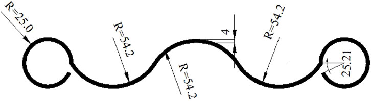
FIGURE 1. Cross section of the three-wave beam steel guardrail.
The wave plate absorbs the impact energy through the vertical stretch of the cross-beam waveform and its own transverse bending deformation, while the contact friction between the protruding surface and the vehicle slows down the driving speed, guiding the vehicle steering, forcing the errant vehicle to turn back to the correct track, and recovering the normal driving position. This type of board could effectively prevent the vehicle from running off the road to ensure the safety of drivers and passengers, thus reducing the loss (Chen et al., 2021). The soft and flexible wave steel board or the semi-rigid guardrail has a strong impact energy absorption property, preventing the vehicle from rushing out of the road and offering double protection to vehicles and the road. Meanwhile, the whole structure illustrates a good line-of-sight induction function, aligned with the shape of the road. The material is used for building guardrails of corners with small radius due to its attractive style as it is easy to maintain, repair, and replace the damage.
3 Finite element modeling
3.1 Finite element model of the guardrail
The guardrail damage is generally about 3–5 spans, while in this article, the impact damage is the intermediate, that is, seven spans. The guardrail plate was 28 m long, and there was a 4-m distance between the adjacent posts (Huang et al., 2020a; Bai et al., 2021; Sun et al., 2021; Zhou et al., 2022). The finite element model was built by ANSYS, a large general software application. The whole finite element model adopted the solid with 45 units, and the mesh size was 0.02 m, thus generating a total of 4,36,679 units.
3.1.1 Finite element model of the guardrail plate
According to the expressway W-beam steel guardrail, the guardrail material was carbon structural steel with an elastic modulus of 200 GPa, the yield stress of 235 MPa, Poisson’s ratio of 0.33, and a density of 7,860 kg/m3, but the guardrails are made of Q235 steel in actual construction (Liu et al., 2021). The finite element model and mesh generation of the guardrail plate are shown in Figure 2.
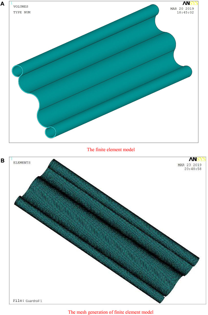
FIGURE 2. Finite element model and mesh generation of the guardrail plate. (A): Finite element model; (B): The mesh generation of finite element model.
3.1.2 Finite element model of the anti-obstruction block
The finite element model and mesh generation of the anti-obstruction block are shown in Figure 3.
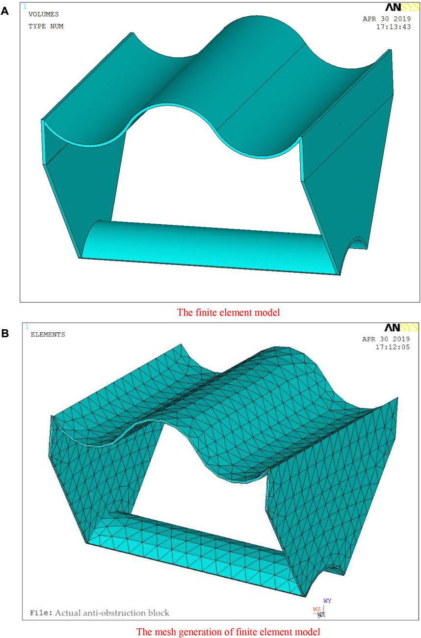
FIGURE 3. Finite element model and mesh generation of the anti-obstruction block. (A): Finite element model; (B): The mesh generation of finite element model.
3.1.3 Finite element model of the post
The post is the supporting part in the guardrail, bearing the bending moment under the impact. According to the Guidelines for Design of Highway Safety Facilities, the post size was Φ140*4.5 mm and 2,150 mm high, of which 1,400 mm was buried underground and 750 mm above the ground. The finite element model and mesh generation of the post are shown in Figures 4A and B, while the finite element model of the guardrail is shown in Figure 4C. The material of the post was the same as that of the guardrail plate.
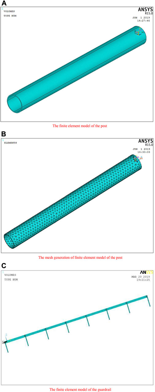
FIGURE 4. Finite element model and mesh generation of the post and the guardrail. (A): Finite element model of the post; (B): The mesh generation of finite element model; (C): Finite element model.
3.2 Constraint application method of different embedding methods
3.2.1 The concrete-embedded post
If the post was embedded in the concrete, the plastic hinge deformation of the post under the impact started from the joint part of the post and the ground, while the ground showed no deformation or displacement (Sun et al., 2019). When simulating the connection of the post to the sub-grade, we fixed all the degrees of freedom of the nodes below the surface of the post.
3.2.2 The soil-embedded post
The complex interaction between the post and the soil has attracted academics worldwide to conduct extensive studies. They found that the maximum bending moment position on the post after the guardrail was impacted by the vehicle was independent of the burying depth in the soil, which was 400 mm under the ground (Zhang et al., 2019). To specify the stimulation method adopted in this article, it was the freedom degree restriction of posts embedded 400 mm in the ground that stimulated the interaction between the soil and the post.
3.3 Determination of the vehicle impact force
The simulation of the vehicle impacting the guardrail used the static equivalent method, prior to which we should determine the impact load (Huang et al., 2020b; Zhang et al., 2020a; Wei et al., 2021; Mousavi et al., 2022). According to the mathematical model and basic hypotheses specified in the Guidelines for Design of Highway Safety Facilities, we derived a formula for calculating the impact force between the vehicle and the guardrail; this calculation adopted the static equivalent method to simulate how the vehicle impacts the guardrail (Eq. 1).
where V is the vehicle impact speed, m/s; θ is the impact angle; b is the vehicle width, m; C is the distance of the center of gravity of the vehicle from the front bumper, m; and Z is the transverse deformation of the guardrail, m. According to the mathematical model and basic hypotheses given in the Guidelines for Design of Highway Safety Facilities, for metal guardrails, where Z = 0.3–0.6 m, the calculation used the lowest impact force of Z = 0.3 m. In addition, according to the Standard for Safety Performance Evaluation of Highway Barriers, the impact angle was set at 20°. The calculation parameters of the guardrail impact are shown in Table 1.
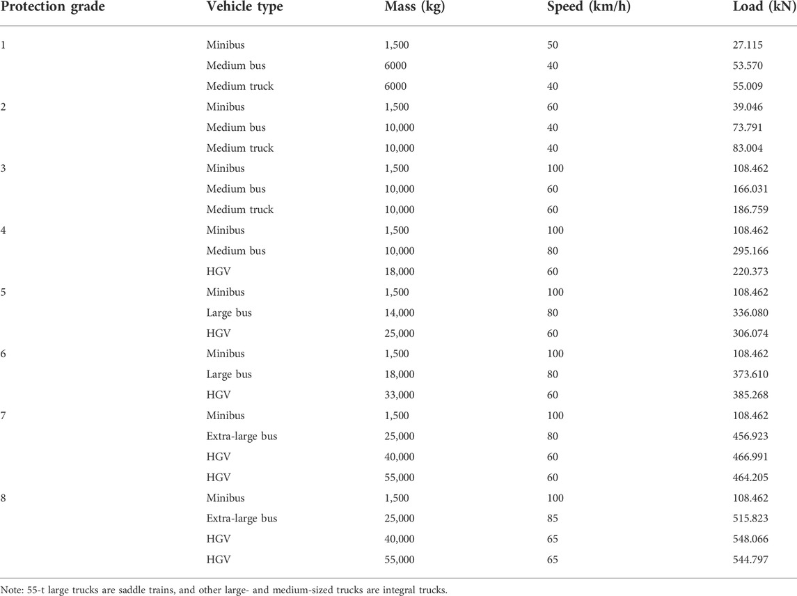
TABLE 1. Calculation parameters of the guardrail impact.
4 Analysis of the impact deformation of the guardrail
In a real-life scenario, impact forces yielded the metal guardrail. The impact forces of vehicles vary at different speeds and with different masses, so the yield deformation degrees of the guardrail range significantly. Therefore, the following analysis focuses on simulating the impact deformation of vehicles with different masses (1.5, 25, 40, and 55 t) and at different speeds (100, 85, and 65 km/h) when impacting the guardrail at 20°. The table mentioned earlier lists commonly seen vehicle types on expressways, and the driving speed represents the restricted speed of each type. Hence, the simulated displacement diagram typically reflects the real accident scenarios and so did the simulation results.
4.1 The concrete-embedded post
4.1.1 The guardrail was impacted by the 1.5-t minibus at the speed of 100 km/h
The deformation geometry of the guardrail impacted by the 1.5-t minibus at the speed of 100 km/h from an angle of 20° is shown in Figure 5.
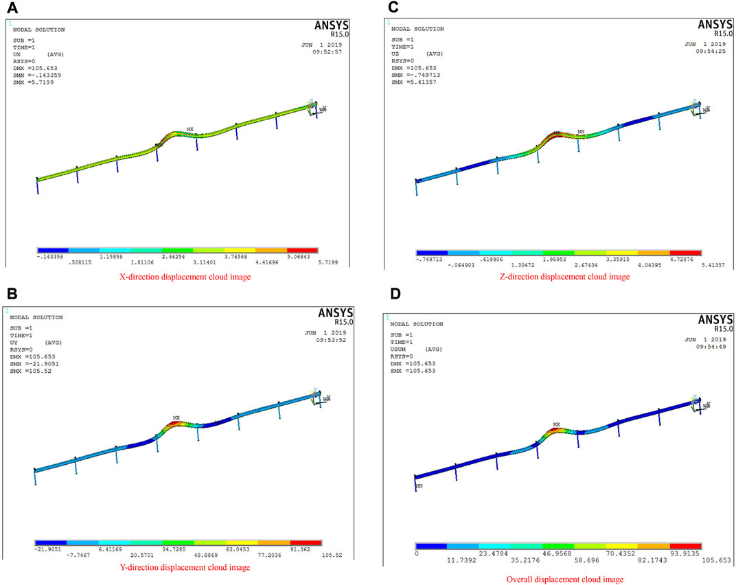
FIGURE 5. Displacement cloud diagram of a three-wave beam steel guardrail (impacted by the 1.5-t minibus at the speed of 100 km/h from an angle of 20°, the concrete-embedded post). (A):X-direction displacement cloud image of three-wave beam steel guardrail; (B):Y-direction displacement cloud image of three-wave beam steel guardrail; (C):Z-direction displacement cloud image of three-wave beam steel guardrail; (D): Overall displacement cloud diagram of three-wave beam steel guardrail.
According to Figure 5, the displacement of the guardrail in the X, Y, and Z directions was 5.7199, 105.52, and 5.41357 mm, respectively, of which the maximum displacement was 105.653 mm. As explained earlier, the yield displacement of the guardrail in the Y direction is the largest when the vehicle collides in front because the wave platform of the new guardrail absorbs impact energy through the vertical stretching of the beam waveform, followed by its own transverse bending deformation, but it absorbs less impact force in the Y direction.
4.1.2 The guardrail impacted by the 25-t extra-large bus at the speed of 85 km/h
The impact geometry of the guardrail impacted by the 25-t extra-large bus at the speed of 85 km/h from an angle of 20° is shown in Figure 6.
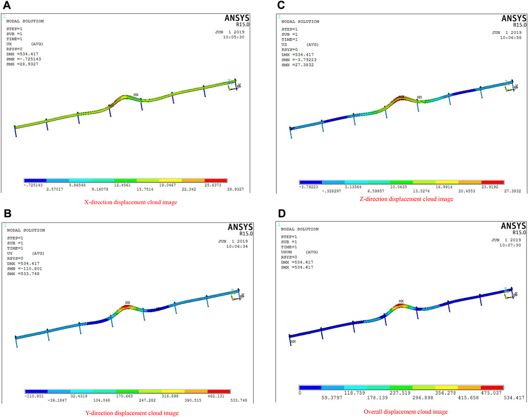
FIGURE 6. Displacement cloud diagram of a three-wave beam steel guardrail (impacted by the 25-t extra-large bus at the speed of 85 km/h from an angle of 20°, the concrete-embedded post). (A): X-direction displacement cloud image of three-wave beam steel guardrail. (B): Y-direction displacement cloud image of three-wave beam steel guardrail. (C): Z-direction displacement cloud map of three-wave beam steel guardrail. (D): Overall displacement cloud image of three-wave beam steel guardrail.
According to Figure 6, the displacement of the three-wave beam steel guardrail in the X, Y, and Z directions was 28.9327, 533.748, and 27.3832 mm, respectively, of which the maximum displacement of the guardrail was 534.417 mm. According to the displacement results, higher vehicle weight and speed will cause larger deformation to the guardrail. Similar to the previous experiment, the yield displacement of the guardrail in the Y direction is still the largest because the wave platform of the new guardrail absorbs the impact energy through the vertical stretching of the beam waveform, followed by its own lateral bending deformation, but the absorption of the impact force in the Y direction is less.
4.1.3 The guardrail impacted by the 40-t HGV at the speed of 65 km/h
The impact geometry of the guardrail impacted by the 40-t HGV at the speed of 65 km/h from an angle of 20° is shown in Figure 7.
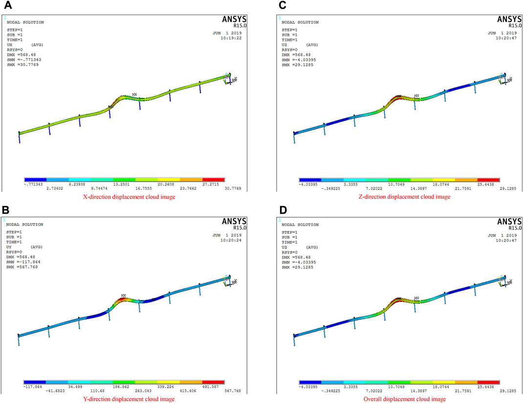
FIGURE 7. Displacement cloud diagram of a three-wave beam steel guardrail (impacted by the 40-t HGV at the speed of 65 km/h from an angle of 20°, the concrete-embedded post). (A): X-direction displacement cloud image of three-wave beam steel guardrail. (B): Y-direction displacement cloud image of three-wave beam steel guardrail. (C): Z-direction displacement cloud map of three-wave beam steel guardrail. (D): Overall displacement cloud image of three-wave beam steel guardrail.
According to Figure 7, the displacement of the guardrail in the X, Y, and Z directions was 30.7769, 567.768, and 29.1285 mm, respectively, while the maximum displacement of the guardrail was 568.48 mm. The comparison results of Figures 6, 7 show that the weight of the vehicle caused a greater impact deformation to the guardrail than the speed because of the greater inertia force of a higher weight.
4.1.4 The guardrail impacted by the 55-t HGV at the speed of 65 km/h
The impact geometry of the guardrail impacted by the 55-t HGV at the speed of 65 km/h from an angle of 20° is shown in Figure 8.
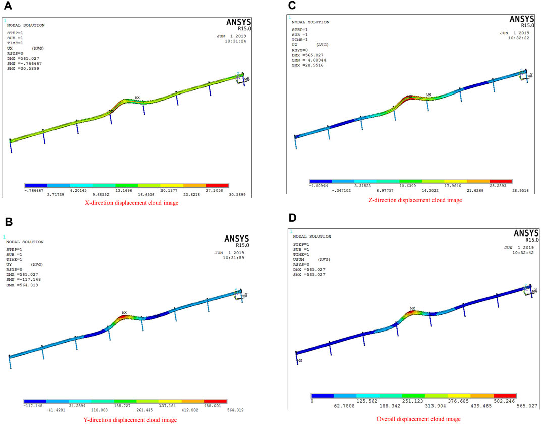
FIGURE 8. Displacement cloud diagram of a three-wave beam steel guardrail (impacted by the 55-t HGV at the speed of 65 km/h from an angle of 20°, the concrete-embedded post). (A): X-direction displacement cloud image of three-wave beam steel guardrail. (B): Y-direction displacement cloud image of three-wave beam steel guardrail. (C): Z-direction displacement cloud map of three-wave beam steel guardrail. (D): Overall displacement cloud image of three-wave beam steel guardrail.
According to Figure 8, the displacement of the guardrail in the X, Y, and Z directions was 30.5899, 564.319, and 28.9516 mm, respectively, while the maximum displacement of the guardrail was 565.027 mm. By comparing Figures 7, 8, it can be concluded that the impact on the guardrail will be enlarged by a constant speed and a greater vehicle weight.
5 Conclusion
According to Figures 4–8, the maximum deformation of the guardrail with the concrete-embedded post was 568.48 mm when it was impacted by vehicles of different masses and speeds from an angle of 20°. The result was less than 750 mm, the maximum dynamic deformation specified in the guidelines and standards, reaching Grade 8 protection (Zhang et al., 2020b; Xu et al., 2022a; Xu et al., 2022b; Gu et al., 2022).
5.1 The soil-embedded guardrail post
5.1.1 The guardrail impacted by the 1.5-t minibus at the speed of 100 km/h
The impact geometry of the guardrail impacted by the 1.5-t minibus at the speed of 100 km/h from an angle of 20° is shown in Figure 9. According to Figure 9, the displacement of the guardrail in the X, Y, and Z directions was 12.2465, 125.754, and 9.45474 mm, respectively, while the maximum displacement of the guardrail was 126.28 mm (Xu et al., 2021).
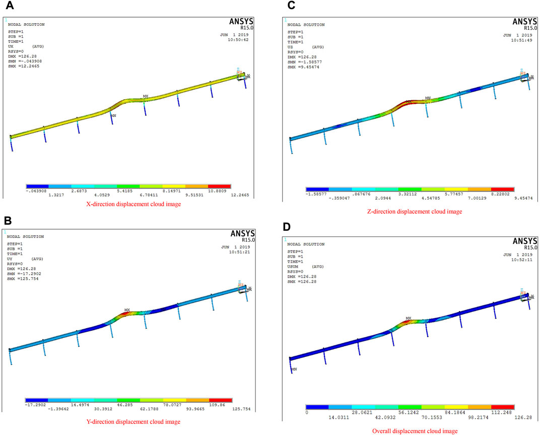
FIGURE 9. Displacement cloud diagram of a three-wave beam steel guardrail (impacted by the 1.5-t minibus at the speed of 100 km/h from an angle of 20°, the soil-embedded guardrail post). (A): Cloud image of displacement in X direction of three-wave beam steel guardrail. (B): Y-direction displacement cloud image of three-wave beam steel guardrail. (C): Z-direction displacement cloud map of three-wave beam steel guardrail. (D): Overall displacement cloud image of three-wave beam steel guardrail.
5.1.2 The guardrail impacted by the 25-t extra-large bus at the speed of 85 km/h
The impact geometry of the guardrail impacted by the 25-t extra-large bus at the speed of 85 km/h from an angle of 20° is shown in Figure 10. According to Figure 10, the displacement of the guardrail in the X, Y, and Z directions was 61.9459, 636.095, and 47.8244 mm, respectively, while the maximum displacement of the guardrail was 638.753 mm.
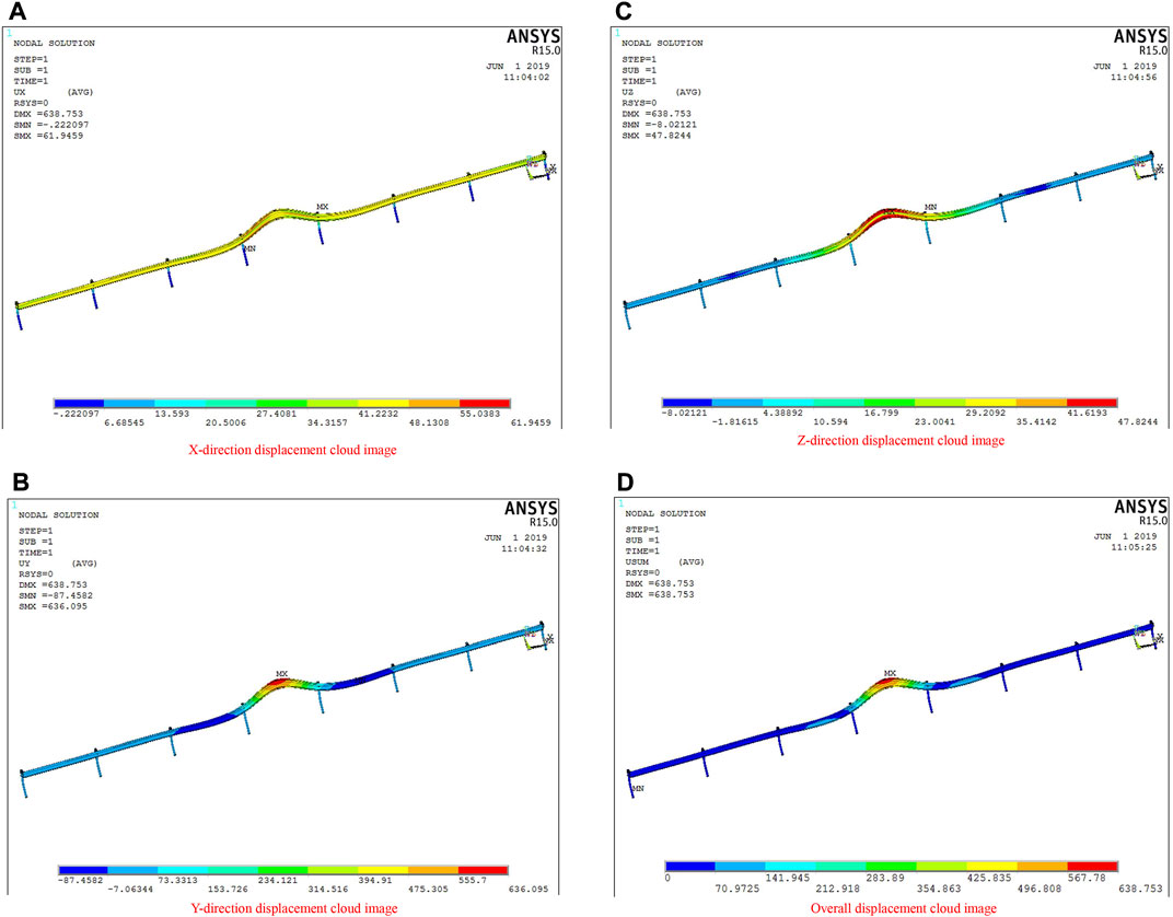
FIGURE 10. Displacement cloud diagram of a three-wave beam steel guardrail (impacted by the 25-t extra-large bus at the speed of 85 km/h from an angle of 20°, the soil-embedded guardrail post). (A): X-direction displacement cloud diagram of three-wave beam steel guardrail. (B): Displacement cloud diagram of three-wave beam steel guardrail in Y direction. (C): Z-direction displacement cloud map of three-wave beam steel guardrail. (D): The overall displacement cloud diagram of the three-wave beam steel guardrail.
5.1.3 The guardrail impacted by the 40-t HGV at the speed of 65 km/h
Figure 11 shows the impact geometry of the guardrail impacted by the 40-t HGV at the speed of 65 km/h from an angle of 20°. According to Figure 11, the displacement of the guardrail in the X, Y, and Z directions was 65.8945, 676.639, and 50.8727 mm, respectively, while the maximum displacement of the guardrail was 679.466 mm.
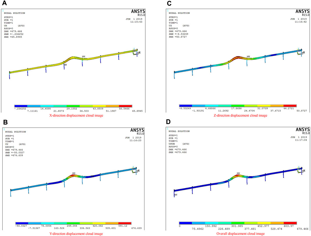
FIGURE 11. Displacement cloud diagram of a three-wave beam steel guardrail (impacted by the 40-t HGV at the speed of 65 km/h from an angle of 20°, the soil-embedded guardrail post). (A): X-direction displacement cloud diagram of three-wave beam steel guardrail. (B): Displacement cloud diagram of three-wave beam steel guardrail in Y direction. (C): Displacement cloud diagram of three-wave beam steel guardrail in Z direction. (D): The overall displacement cloud diagram of the three-wave beam steel guardrail.
5.1.4 The guardrail impacted by the 55-t HGV at the speed of 65 km/h
The impact geometry of the guardrail impacted by the 55-t HGV at the speed of 65 km/h from an angle of 20° is shown in Figure 12. According to Figure 12, the displacement of the guardrail in the X, Y, and Z directions was 65.494, 672.528, and 50.5636 mm, respectively, while the maximum displacement of the guardrail was 675.338 mm.
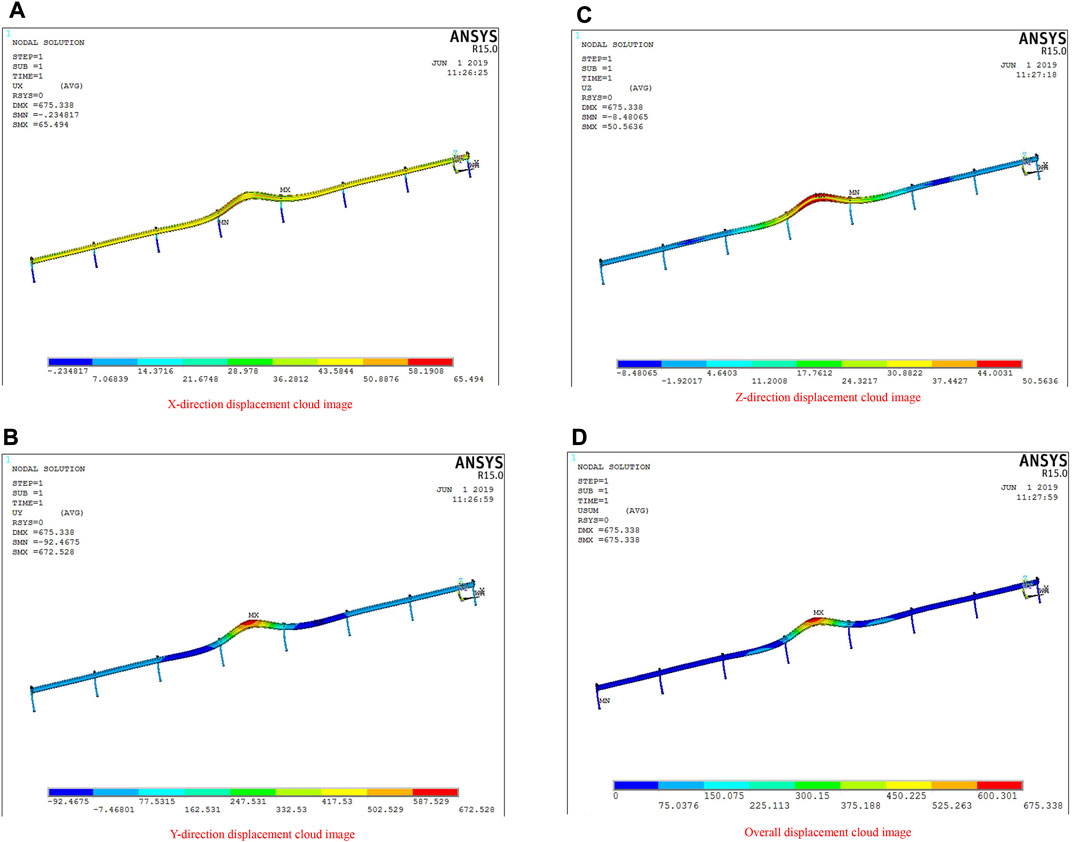
FIGURE 12. Displacement cloud diagram of a three-wave beam steel guardrail (impacted by the 55-t HGV at the speed of 65 km/h from an angle of 20°, the soil-embedded guardrail post). (A): Displacement cloud diagram of three-wave beam steel guardrail in X direction. (B): Displacement cloud diagram of three-wave beam steel guardrail in Y direction. (C): Displacement cloud diagram of three-wave beam steel guardrail in Z direction. (D): The overall displacement cloud diagram of the three-wave beam steel guardrail.
In Figures 9–12, the maximum deformation of the guardrail with the soil-embedded post was 679.466 mm when it was impacted by vehicles of different masses at various speeds from an angle of 20°. The result was less than the maximum dynamic deformation of 750 mm in the specification, reaching the requirements of Grade 8 protection.
5.2 Summary
To sum up, for the new three-wave beam steel guardrail with a given thickness of 4 mm and their posts embedded both in the concrete and soil, the maximum deformation of the guardrail when it was impacted by the vehicles with different masses and at different speeds was less than the maximum dynamic deformation specified in the guidelines and standards, reaching the requirements of Grade 8 protection. In particular, the guardrail plate’s streamlined and smooth design is compatible with the curvature of the road and serves as an excellent visual guide, successfully preventing vehicles from veering off the road. The wave plane of the guardrail plate simultaneously absorbs the impact energy through the vertical stretching of the beam waveform and transverse beam waveform bending deformation. The protruding surface decreases the running speed, directs the vehicle to turn, pushes the vehicle to return to the right track, and restores the regular running position by contact friction. As a result, this new steel guardrail with a three-wave beam satisfies the Grade 8 protection criteria.
6 Conclusion
As the new three-wave beam steel guardrail’s width is fixed at 4 mm, the maximum displacement of the guardrail with the concrete-embedded and soil-embedded posts was 568.48 and 679.466 mm, respectively, when they were impacted by the vehicles with different masses and at different speeds from an angle of 20°. Such a result was less than 750 mm, the maximum deformation specified in the guidelines and standards, satisfying the Grade 8 protection criteria. In conclusion, for a new three-wave beam steel guardrail with a thickness of 4 mm, regardless of the post embedded in concrete or soil, the maximum deformation of the guardrail impacted by vehicles of different masses and at different speeds is less than the designated maximum dynamic deformation criteria and standards specified in Grade 8 protection.
The impact between the vehicle and the guardrail in the simulation was different from the actual situation, and the calculation process of finite element simulation in this article was largely simplified; therefore, the results of the numerical analysis are for reference only. We recommend researchers carry out relevant experiments for further study.
Data availability statement
The original contributions presented in the study are included in the article/supplementary material; further inquiries can be directed to the corresponding author.
Author contributions
KG developed the conception and design of the study. CW established the database. KG and LS carried out the statistical analysis. KG wrote the initial draft of the manuscript. All authors contributed to the manuscript revision and read and approved the submitted version.
Funding
This study was supported by the Research on the Application Technology of Economical High-Strength Edge Crimped Steel Guardrail (No. 2020J-2-21).
Conflict of interest
Author KG is employed by the Transport Development Group Co., Ltd., of Henan Province. Authors CW and LS are employed by Rioh Traffic Safety Co., Ltd.
Publisher’s note
All claims expressed in this article are solely those of the authors and do not necessarily represent those of their affiliated organizations, or those of the publisher, the editors, and the reviewers. Any product that may be evaluated in this article, or claim that may be made by its manufacturer, is not guaranteed or endorsed by the publisher.
References
Abubaker, K., Yangwei, W., Huanwu, C., Faisal, N., Ghulam, Y., Muhammad, U., et al. (2019). Ballistic behaviour of spray formed AA7055 aluminum alloy against tungsten core projectile impact. Vacuum 159, 482–493. doi:10.1016/j.vacuum.2018.10.073
Bai, Y., Nardi, D. C., Zhou, X., Picón, R. A., and Flórez-López, J. (2021). A new comprehensive model of damage for flexural subassemblies prone to fatigue. Comput. Struct. 256, 106639. doi:10.1016/j.compstruc.2021.106639
Chen, Z., Zhang, H., He, X., Fan, G., Li, X., He, Z., et al. (2021). Fabrication of cellulosic paper containing zeolitic imidazolate framework and its application in removal of anionic dye from aqueous solution. BioResources 16 (2), 2644–2654. doi:10.15376/biores.16.2.2644-2654
Gu, M., Mo, H., Qiu, J., Yuan, J., and Xia, Q. (2022). Behavior of floating stone columns reinforced with geogrid encasement in model tests. Front. Mat. 9, 980851. doi:10.3389/fmats.2022.980851
Huang, H., Huang, M., Zhang, W., and Yang, S. (2020). Experimental study of predamaged columns strengthened by HPFL and BSP under combined load cases. Struct. Infrastructure Eng. 17 (9), 1210–1227. doi:10.1080/15732479.2020.1801768
Huang, H., Huang, M., Zhang, W., Pospisil, S., and Wu, T. (2020). Experimental investigation on rehabilitation of corroded RC columns with BSP and HPFL under combined loadings. J. Struct. Eng. (N. Y. N. Y) 146 (8), 4020157. doi:10.1061/(asce)st.1943-541x.0002725
Jia, Y. H., Jia, N., and Gao, S. D. (2012). Present situation and analysis of occupant risk assessment technology of highway guardrail abroad. J. China & Foreign Highw. 31 (6), 282–285.
Khan, M. A., Wang, Y., Malik, A., Abdul, M. F., Nazeera, W., and Qamar, K., (2019). Microstructure characterization of 7055-T6, 6061-T6511 and 7A52-T6 Al alloys subjected to ballistic impact against heavy tungsten alloy projectile. Archives Civ. Mech. Eng. 19 (4), 1484–1496. doi:10.1016/j.acme.2019.10.001
Khan, M. A., Wang, Y., Yasin, G., Nazeera, F., Yasinc, G., and Khand, W. Q. T., (2019). Microstructure characteristic of spray formed 7055 Al alloy subjected to ballistic impact by two different steel core projectiles impact. J. Mater. Res. Technol. 8 (6), 6177–6190. doi:10.1016/j.jmrt.2019.10.012
Liu, M., Xue, Z., Zhang, H., and Li, Y. (2021). Dual-channel membrane capacitive deionization based on asymmetric ion adsorption for continuous water desalination. Electrochem. Commun. 125, 106974. doi:10.1016/j.elecom.2021.106974
Mousavi, A. A., Zhang, C., Masri, S. F., and Gholipour, G. (2022). Structural damage detection method based on the complete ensemble empirical mode decomposition with adaptive noise: A model steel truss bridge case study. Struct. Health Monit. 21 (3), 887–912. doi:10.1177/14759217211013535
Nicol, D. A. (2009). Information: Manual for assessing safety hardware. USA: Memorandum. US Department of Transportation, Federal Highway Administration.
Sun, M., Yan, L. L., Zhang, L. H., Song, L. F., Guo, J. B., and Zhang, H. F. (2019). New insights into the rapid formation of initial membrane fouling after in-situ cleaning in a membrane bioreactor. Process Biochem. 78, 108–113. doi:10.1016/j.procbio.2019.01.004
Sun, M., Hou, B. D., Wang, S. L., Zhao, Q. N., Zhang, L. H., Song, L. F., et al. (2021). Effects of NaClO shock on MBR performance under continuous operating conditions. Environ. Sci. Water Res. Technol. 7 (2), 396–404. doi:10.1039/d0ew00760a
Wei, J., Xie, Z., Zhang, W., Luo, X., Yang, Y., and Chen, B. (2021). Experimental study on circular steel tube-confined reinforced UHPC columns under axial loading. Eng. Struct. 230, 111599. doi:10.1016/j.engstruct.2020.111599
Xie, Y. H., Lei, Z. B., Li, H. X., and Ning, Y. T. (2003). Researching status and developing trends of guardrail on highways. Constr. Des. Proj. 12, 40–43.
Xu, J., Li, Y. F., Ren, C., Wang, S. H., Vanapalli Sai, K., and Chen, G. X. (2021). Influence of freeze-thaw cycles on microstructure and hydraulic conductivity of saline intact loess. Cold Regions Sci. Technol. 181, 103183. doi:10.1016/j.coldregions.2020.103183
Xu, J. W., Zhang, X. Q., Park, S. H., and Guo, K. (2022). The alleviation of perceptual blindness during driving in urban areas guided by saccades recommendation. IEEE Trans. Intell. Transp. Syst. 23, 16386–16396. doi:10.1109/TITS.2022.3149994
Xu, J. W., Park, S. H., Zhang, X. Q., and Hu, J. (2022). The improvement of road driving safety guided by visual inattentional blindness. IEEE Trans. Intell. Transp. Syst. 23 (6), 4972–4981. doi:10.1109/tits.2020.3044927
Zhang, H., Sun, M., Song, L., Guo, J., and Zhang, L. (2019). Fate of NaClO and membrane foulants during in-situ cleaning of membrane bioreactors: Combined effect on thermodynamic properties of sludge. Biochem. Eng. J. 147, 146–152. doi:10.1016/j.bej.2019.04.016
Zhang, H., Guan, W., Zhang, L., Guan, X., and Wang, S. (2020a). Degradation of an organic dye by bisulfite catalytically activated with iron manganese oxides: The role of superoxide radicals. ACS Omega 5 (29), 18007–18012. doi:10.1021/acsomega.0c01257
Zhang, K., Jia, C. Z., Song, Y., Jiang, S., Jiang, Z. X., Wen, M., et al. (2020b). Analysis of lower cambrian shale gas composition, source and accumulation pattern in different tectonic backgrounds: A case study of weiyuan block in the upper yangtze region and xiuwu basin in the lower yangtze region. Fuel 263, 115978. doi:10.1016/j.fuel.2019.115978
Zheng, Y. N. (2013). Optimization design of highway guardrails based on collision safety of vehicle body. China, Hunan: Hunan University.
Keywords: new three-wave beam guardrail, ANSYS model, anti-impact performance, displacement deformation, simulation analysis
Citation: Guo K, Wang C and Shen L (2022) An experimental study on the impact resistance of a new three-wave beam steel guardrail. Front. Mater. 9:942099. doi: 10.3389/fmats.2022.942099
Received: 05 July 2022; Accepted: 11 October 2022;
Published: 02 November 2022.
Edited by:
Hui Yao, Beijing University of Technology, ChinaReviewed by:
Ghulam Yasin, Beijing University of Chemical Technology, ChinaNansha Gao, Northwestern Polytechnical University, China
Copyright © 2022 Guo, Wang and Shen. This is an open-access article distributed under the terms of the Creative Commons Attribution License (CC BY). The use, distribution or reproduction in other forums is permitted, provided the original author(s) and the copyright owner(s) are credited and that the original publication in this journal is cited, in accordance with accepted academic practice. No use, distribution or reproduction is permitted which does not comply with these terms.
*Correspondence: Chenghu Wang, d2FuZ3hmNDIzQDEyNi5jb20=