 Meixiang Gu
 Haizhao Mo2
- 1School of Civil Engineering, Guangzhou University, Guangzhou, China
- 2China Construction Fourth Engineering Division Corp. Ltd, Guangzhou, China
- 3School of Civil Engineering, Guangzhou University, Guangzhou, China
- 4School of Civil Engineering, Guangzhou University, Guangzhou, China
The bearing capacity and deformation characteristics of floating stone columns were complicated and are not thoroughly understood. In the present study, a series of experimental model tests of floating stone columns under vertical plate loading was performed. This study investigated the influence of geogrid encasement on the behavior of floating stone columns and provided valuable insight into the load-displacement behavior, bulging deformation, load transfer mechanism, and the radial stress of the geogrid encasement. The test results show that the bearing capacity of the floating stone column was significantly improved due to the geogrid encasement. The column with longer encasement showed higher stiffness at large settlements. The bulging deformation pattern of the column changed with different encasement lengths. More vertical pressure transferred from the top of the column to the bottom of the column due to the existence of the geogrid encasement. The fully encased stone columns developed high radial stress and achieved effective confinement of the column. The bearing capacities of the floating-encased stone columns with different encasement lengths were controlled by bulging deformation instead of penetration failure, which gave confidence that the floating-encased stone columns were an effective method for field construction in extensive soft soils.
Introduction
Stone columns were an effective ground improvement technique and were extensively used to deal with soft clay deposits by increasing bearing capacities, controlling settlements, and accelerating the consolidation rate (Han, 2015a; Han, 2015b). In geotechnical design and construction application, the column typically penetrated through the soft clay and rested on a strong stratum, which was called an end-bearing stone column. However, in the situation of vertically extensive soft soils (commonly encountered in coastal areas), it was unnecessary to penetrate through the entire soft soil deposits. The effective column length was suggested not to exceed 10 times the column diameter based on the consideration of performance and economy. Therefore, the column may not reach a strong stratum and float in the soft clay deposits, which were called floating stone columns. In some instances, the construction of floating stone columns was found to be more economical and technically feasible than the end-bearing stone columns.
The ordinary stone columns may not be effective when soft soils are extremely weak (e.g., undrained shear strength less than 15 kPa). The surrounding soft soils may not provide sufficient confining pressure in the shallow depth. The stone column was likely to bulge and failed to carry additional loads. Geosynthetics (such as geogrid and geotextile) were introduced and used to reinforce the stone columns vertically. The geosynthetic encasement can provide additional confining pressure and improve the stiffness and bearing capacity of the columns (Bai et al., 2019; Bai et al., 2021; Bai et al., 2022; Gniel and Bouazza, 2010; Ghazavi and Afshar, 2013; Almeida et al., 2014; Chen et al., 2015; Zhang and Zhao, 2015; Gu et al., 2016; Chen et al., 2018; Gu et al., 2020; Tan et al., 2020).
However, most previous studies focused on either floating stone columns unreinforced with geosynthetics (Ng and Tan, 2014; Shahu and Reddy, 2014; Zhou et al., 2017; Ong et al., 2018; Shan et al., 2022; Zhao et al., 2021), or geosynthetic-encased stone columns that reached a strong stratum (Murugesan and Rajagopal, 2010; Pulko et al., 2011; Yoo and Lee 2012; Gu et al., 2017a; Gu et al., 2017b; Mohapatra and Rajagopal 2017; Schnaid et al., 2017; Kadhim et al., 2018; Kong et al., 2018; Zhou and Kong, 2019a; Zhou and Kong, 2019b; Zhang et al., 2020; Tan et al., 2021). There are limited studies on the performance of floating stone columns reinforced with geosynthetic encasement. Ali et al. (2012) carried out model tests on floating and end-bearing stone columns and found that the full column length gives higher failure stress than encasement over the top half or quarter of the column length. Dash and Bora (2013) investigated the performance of end-bearing stone columns and floating stone columns reinforced with window-mesh encasement (the geosynthetic was called geomesh to model the geogrid). The material properties of the window-mesh were significantly different from those of the geogrid in terms of tensile stiffness and rib width. The widow-mesh was difficult to model the actual behavior of the geogrid, especially the interaction effect between the aggregates and the geogrid. Hasan and Samadhiya (2016) investigated the bearing capacities of vertical encased granular piles by experimental and numerical analysis. Sarvaiya and Solanki (2017) conducted experimental tests on floating stone columns with different encasement lengths. It was suggested that the full length of the encasement was not necessary based on the consideration of the columns’ bearing capacity. Debnath and Dey (2017) suggested that the optimum column length and optimum encasement length of floating stone columns with a geogrid-reinforced sand bed were six and three times the diameter of the column, respectively, using finite element analyses. Kahyaoğlu and Vaníček (2019) presented the behavior of the embankment supported by floating-encased columns using the finite element method. The effect of the encasement stiffness, the basal reinforcement stiffness, and the embankment fill height was investigated. The effective encasement length depended on the surcharge and the strength properties of the column and the soil. Thakur et al. (2021) compared the load capacities of the vertically and horizontally reinforced floating stone columns in model tests. The results indicated that the fully encased stone column had a lower load capacity than the horizontal reinforced stone column using geotextile encasement.
The deformation and load transfer mechanisms were complicated for the floating stone columns reinforced with geogrid encasement and are not thoroughly understood. The bulging deformation controlled the bearing capacity of floating-ordinary stone columns (F-OSC, unreinforced with geosynthetics) if the column was sufficiently long. The failure mode of the floating-encased stone columns (F-ESC, reinforced with geogrid encasement) may change because the large bulging deformation would be limited to a relatively small value due to the geogrid encasement. Moreover, the interaction between the aggregates and the geogrid was important and needed to be investigated further. This study presented a series of model tests on floating stone columns under vertical incremental loads. The influence of geogrid encasement on the behavior of floating stone columns was investigated in terms of load-displacement behavior, bulging deformation, load transfer mechanism, and the radial stress of the geogrid encasement.
Description of the experiment
To investigate the behavior of floating stone columns reinforced with the geosynthetic encasement, a series of plate loading tests was conducted based on unit cell assumption. Table 1 summarizes the model test parameters. The thickness of the clay bed was kept at 1,000 mm in all tests and represents the situation of vertically extensive clay beds. Two parameters (i.e., the column length and the encasement length) were investigated and varied in different tests. The column length varied from 200–800 mm; therefore, the column was floated in the clay beds. The encasement length varied from 0–600 mm and represented the cases of floating-ordinary stone columns (F-OSC) and floating-encased stone columns (F-ESC). Figure 1 shows that the floating stone column was constructed in vertically extensive clay beds and subjected to vertical pressure.
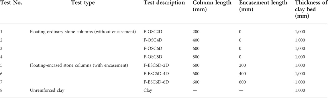
TABLE 1. Summary of model test parameters.
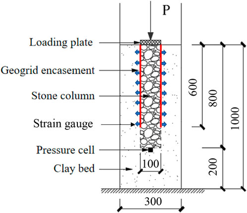
FIGURE 1. Plate loading test on floating-encased stone columns in vertically extensive clay beds.
Materials properties
The soft clay was obtained from a deep excavation project of a subway station in Guangzhou Higher Education Mega Center, located in the Pearl River Delta near the coastal areas of south China. The soil was classified as CL based on the USCS. Undrained triaxial tests were conducted to determine its undrained shear strength and the corresponding moisture content. Table 2 summarizes the detailed properties of soft clay. The aggregates used in the experimental test were angular crashed stones and Figure 2 shows the particle size distribution. The internal friction of the aggregates was determined as 42.90 at a relative density of 62%.

TABLE 2. Properties of the soft clay.
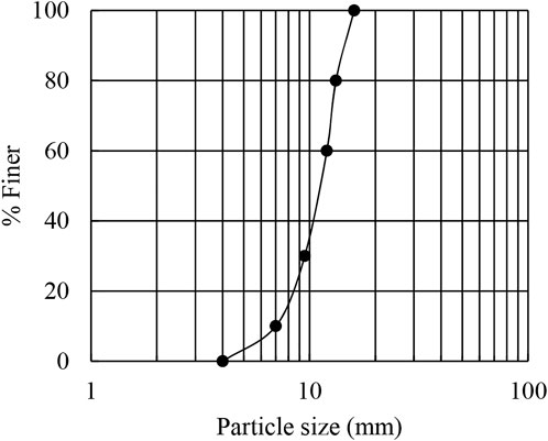
FIGURE 2. Particle size distribution of the aggregates.
The tensile properties and rib dimension of the biaxial geogrid were carefully considered and properly modeled in the model test. A 1-mm thick polypropylene sheet was cut to the aperture size of 10
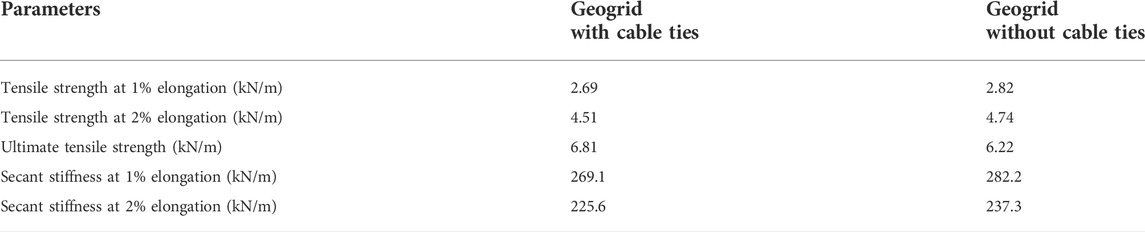
TABLE 3. Tensile properties of the biaxial geogrid.
Preparation of floating-encased stone columns
A cylindrical steel tank was manufactured with an inner diameter and a height of 300 and 1,200 mm, respectively. To facilitate the preparation of the model test, the test tank was uniformly divided into six sections in height. Each section had a height of 200 mm and was connected with the neighboring sections by bolts. Figure 3 shows the testing setup of the model test. Plastic sheets were covered on the inner wall surface of the test tank to reduce friction at the soil–wall interface. The soft clay at a desired moisture content of 36% was filled into the tank by layers. Each layer had a thickness of 50 mm and compacted uniformly. The test tank was covered with a plastic sheet to prevent water evaporation and stood for 3 days after the clay bed reached a thickness of 1,000 mm.
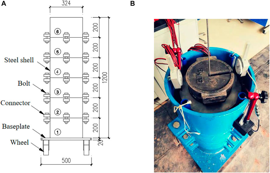
FIGURE 3. Testing set-up: (A) schematic of the test tank; (B) photograph of the plate loading test.
A replacement method was adopted for the construction of floating stone columns. An open-ended plastic pipe with an outer diameter of 100 mm was used and located at the center of the test tank. The bottom of the pipe was first placed on the surface of the soil instead of the bottom of the tank. In the case of a floating-ordinary stone column with a column length of 600 mm (F-OSC6D), the plastic pipe was placed on the soil after the clay bed reached a thickness of 400 mm. After the clay bed reached a thickness of 600 mm, the aggregates of the calculated amount were filled into the pipe to form the stone column 200 mm high and well compacted. The pipe was then pulled up gently by 100 mm in the vertical direction so that the pipe had a minimum embedment depth of 100 mm within the surrounding soil. The pipe was pulled up again after the next 200 mm thick soil was placed and the next stone column section was installed. The aforementioned procedure was repeated until the entire stone column was constructed. In the case of floating-encased stone columns, the geogrid encasement was slid down to the designed depth along the outer surface of the pipe. The encasement was kept in a fixed location during the pulling up of the pipe by additional downward resistance applied by hand and the interlock forces between the aggregates and the geogrid.
Load tests on stone columns
A plate loading test was performed on a single column using the maintained pressure test method. Vertical pressure was applied on the top of the column in 8–10 increments and measured by the mass of the standard weight. The pressure was maintained constant until the rate of the settlement was less than 0.1 mm/h and then the next pressure increment was applied. The loading test was terminated when the settlement exceeded 40 mm, where the vertical pressure may not be maintained and the column failed. Strain gauges were used to measure the hoop strains in the geogrid encasement. The strain gauges were oriented along the circumferential direction of the encasement and fixed onto the geogrid just after a cylindrical geogrid sleeve was formed. An earth pressure cell was installed at the bottom of the column to measure the pressure transferred to the bottom of the column.
Results and discussion
Load-displacement behavior
Figure 4 shows the load-displacement response of floating-ordinary stone columns with different column lengths. The bearing capacity of the clay bed was considerably improved by the F-OSC. The ultimate bearing capacity of the column was defined as the vertical pressure applied at the settlement of 20% of the loading plate diameter (i.e., 20 mm). The ultimate bearing capacity of the F-OSC was 40.4, 50.3, 53.3, and 55.7 kPa for the column lengths at 200, 400, 600, and 800 mm, respectively. The bearing capacity of the clay bed (e.g., 27.1 kPa at the same settlement) was improved by 1.9 times due to the existence of the F-OSC with a column length of 400 mm. It was observed that the bearing capacity may not be improved linearly with the increasing column lengths. The increment of the bearing capacity was small for the column length varying from 400 to 800 mm. An effective column length of 600 mm was determined in this study based on the consideration of the bearing capacity. Therefore, the floating stone column with a length of 600 mm was selected as a baseline case for the investigation of the influence of the geogrid encasement on floating stone columns.
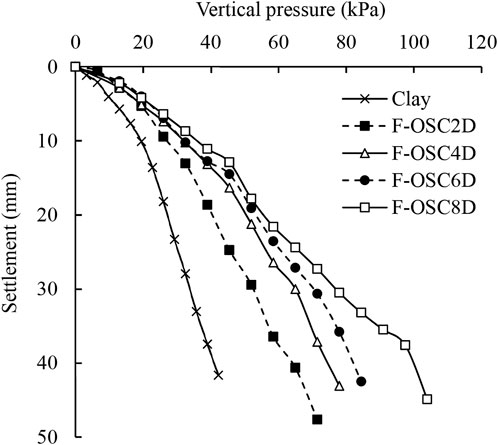
FIGURE 4. Load-displacement curve of floating-ordinary stone columns with different column lengths.
Figure 5 shows the load-displacement response of floating-encased stone columns with different encasement lengths. The bearing capacity of the floating stone column was significantly improved due to the geogrid encasement. The ultimate bearing capacities of the F-ESC were 68.0, 78.8, and 88.5 kPa for the encasement lengths at 200, 400, and 600 mm, respectively. At the beginning loading stage (e.g., the settlement was less than 10 mm), the F-ESC with different encasement lengths showed similar vertical pressure-settlement behavior. The granular aggregates moved laterally and the column mobilized bulging deformation gradually at this stage. The column stiffness decreased with the increase in the settlement due to the discrete nature of the granular material. Figure 5 shows that the F-ESC with longer encasement maintained higher stiffness at large settlements. The fully encased column (F-ESC6D-6D) showed good bearing capacity and its stiffness began to decrease until the settlement reached 20 mm.
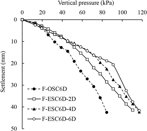
FIGURE 5. Load-displacement curve of floating-encased stone columns with different encasement lengths.
Bulging deformation
The strain gauges were attached to the surface of the geogrid encasement to measure the circumferential strains. The value of circumferential strains was equal to the radial strains of the column due to the axial symmetry of the cylindrical stone columns. Figure 6 shows the bulging deformation profiles of floating-encased stone columns with different encasement lengths subjected to vertical pressures.
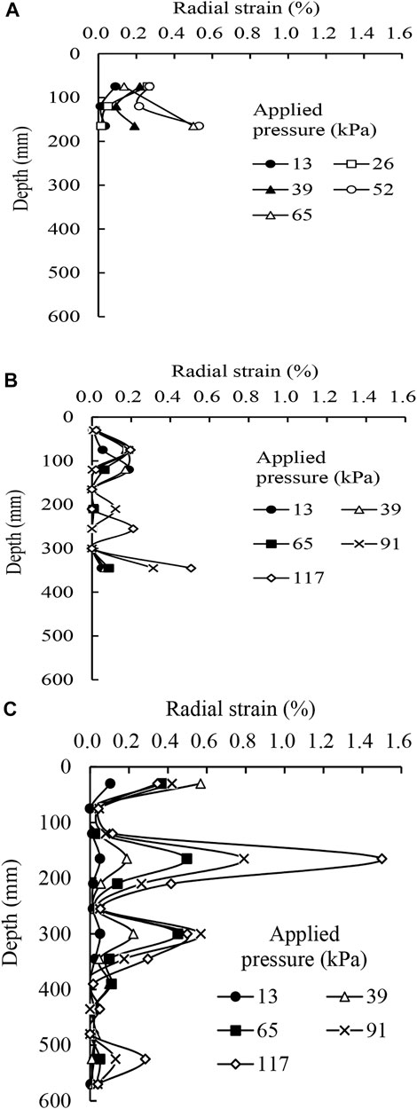
FIGURE 6. Bulging deformation of floating-encased stone columns with different encasement lengths: (A) 200 mm, (B) 400 mm, and (C) 600 mm.
Figures 6A,B show that the radial strain of the F-ESC increased with the applied pressure. The recorded maximum value of the radial strain was 0.53 and 0.51%, respectively, for the columns with the encasement length of 200 and 400 mm. The strain gauges in the F-ESC6D-2D test malfunctioned after the applied pressure exceeded 65 kPa; therefore, no more data were recorded in this test. Large radial strains happened near the base of the encasement sleeve in these two tests. The bulging deformation of the column in the reinforced section was limited due to the encasement. The unreinforced section (i.e., the column below the reinforcement base) may develop large bulging deformation. Bulging failure in the unreinforced section controlled the ultimate bearing capacity of the partially encased stone column, which was similar to that of the end-bearing encased stone column (Gu et al., 2016). The fully encased stone column (F-ESC6D-6D) shows a different bulging deformation pattern along the column depth. Figure 6C shows that large bulging deformation happened at a column depth of 165 mm instead of the base of the encasement sleeve. The recorded maximum value of the radial strain was 1.5%, which was close to the ultimate tensile strain of the geogrid. The column developed bulging failure in the upper reinforced section (within a depth of 2 times the column diameter), which was similar to that of the end-bearing encased stone column.
The bulging deformations of the partially and fully floating-encased stone column were similar to those of the corresponding end-bearing stone columns. This demonstrated that the floating-encased stone column was an effective and reliable method to improve the vertically extensive soft clay deposits.
Load transfer mechanism
To evaluate the applied pressure transferred from the top of the column to the bottom of the column, a ratio of the stress at the bottom to that at the top, referred to as the stress reduction ratio can be calculated. The pressure transferred to the bottom of the stone column was measured using the earth pressure cell installed at the bottom of the column. Figure 7 shows the stress reduction ratio plotted against the settlement for the floating ordinary stone columns with different column lengths. The stress reduction ratio was less than 0.5 for all tests. The value of the stress reduction ratio typically decreased with the increase in the settlement except for the case of F-OSC2D. The short column may penetrate the soft clay instead of bulging failure. The long column (e.g., F-OSC4D, F-OSC6D, and F-OSC8D) showed a smaller stress reduction ratio and less pressure transferred to the bottom of the column. The applied pressure transferred to the bottom of the long column was less than 20% after the column reached a settlement of 20 mm. The bulging deformation dominated the failure mechanism of the floating ordinary stone columns.
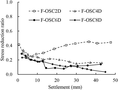
FIGURE 7. Stress reduction ratio of floating-ordinary stone columns with different column lengths.
Figure 8 shows the stress reduction ratio plotted against the settlement for the floating encased stone columns with different encasement lengths. The stress reduction ratio of the encased stone column was higher than that of the ordinary stone column. The encased column had good stiffness due to the effective confinement provided by the encasement sleeve. More pressure was transferred from the top of the column to the bottom of the column. The stress reduction ratio of the fully encased stone column (e.g., F-ESC6D-6D) showed a similar trend with that of the ordinary stone column (e.g., F-OSC6D) because of their same location of bulging deformation. The bulging failure of these two columns both happened within a column depth of 2 times the column diameter. The partially encased column (e.g., F-ESC6D-2D and F-ESC6D-4D) showed a high stress reduction ratio at large settlements. A new shear zone developed in the bulging section (i.e., the unreinforced section below the reinforcement base); thus, the column acted like a pile and more pressure was transferred to the bottom.
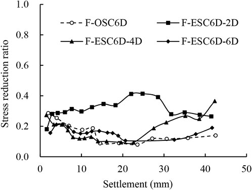
FIGURE 8. Stress reduction ratio of floating-encased stone columns with different encasement lengths.
Radial stress of the encasement
The circumferential strains of the geogrid encasement were measured by using strain gauges. The hoop force (
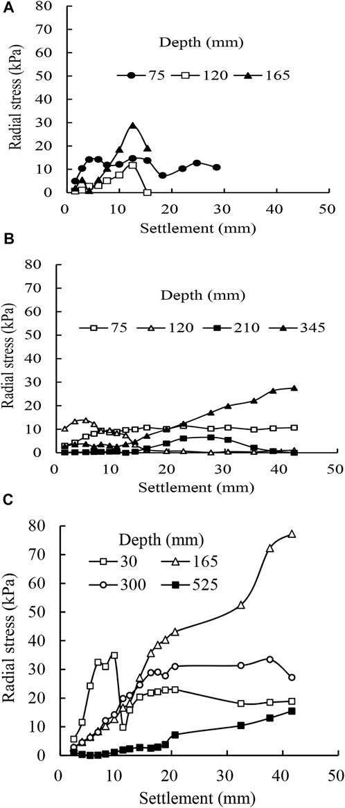
FIGURE 9. Radial stress of floating-encased stone columns with different encasement lengths: (A) 200 mm, (B) 400 mm, and (C) 600 mm.
Conclusion
In the present study, experimental model tests were performed on floating stone columns reinforced with a geogrid encasement. The following conclusions can be made from this study.
1) The bearing capacity of the floating stone column was significantly improved due to the geogrid encasement. The column with longer encasement showed high stiffness at large settlements.
2) The partially and fully encased stone column showed different bulging deformation patterns and developed large radial strains near the base of the encasement sleeve and at a shallow depth of 2 times the column diameter, respectively.
3) The floating-encased stone column showed good stiffness and more vertical pressure transferred from the top of the column to the bottom of the column due to the effective confinement provided by the geogrid encasement.
4) The radial stresses provided by the encasement sleeve were not constant and varied with the settlement. The fully encased stone columns (F-ESC6D-6D) developed high radial stress and achieved effective confinement of the column.
5) The bulging deformation controlled the bearing capacities of the floating-encased stone columns with different encasement lengths, which gave confidence that the geosynthetic-encased stone columns floated in extensive soft soils was an effective method for field construction.
Data availability statement
The original contributions presented in the study are included in the article/Supplementary Material; further inquiries can be directed to the corresponding author.
Author contributions
MG was in charge of the whole research and model tests. JY was in charge of the model tests and paper preparation. HM, JQ, and QX were in charge of the model tests and data analysis.
Funding
This research was funded by the National Natural Science Foundation of China (Grant Nos. 51908150 and 51908151) and the Guangzhou City Technology and Science Program (202102010456). The aforementioned support was appreciated.
Conflict of interest
Author HM was employed by China Construction Fourth Engineering Division Corp. Ltd.
The remaining authors declare that the research was conducted in the absence of any commercial or financial relationships that could be construed as a potential conflict of interest.
Publisher’s note
All claims expressed in this article are solely those of the authors and do not necessarily represent those of their affiliated organizations, or those of the publisher, the editors, and the reviewers. Any product that may be evaluated in this article, or claim that may be made by its manufacturer, is not guaranteed or endorsed by the publisher.
References
Ali, K., Shahu, J. T., and Sharma, K. G. (2012). Model tests on geosynthetic-reinforced stone columns: A comparative study. Geosynth. Int. 19 (4), 292–305. doi:10.1680/gein.12.00016
Almeida, M. S., Hosseinpour, I., Riccio, M., and Alexiew, D. (2014). Behavior of geotextile-encased granular columns supporting test embankment on soft deposit. J. Geotech. Geoenviron. Eng. 141 (3), 04014116. doi:10.1061/(asce)gt.1943-5606.0001256
ASTM (2015). Standard test method for determining tensile properties of geogrids by the single or multi-rib tensile method (ASTM International: West Conshohocken, PA). D6637/D6637M-15.
Bai, B., Wang, Y., Rao, D., and Bai, F. (2022). The effective thermal conductivity of unsaturated porous media deduced by pore-scale SPH simulation. Front. Earth Sci. (Lausanne). 10. doi:10.3389/feart.2022.943853
Bai, B., Yang, G., Li, T., and Yang, G. (2019). A thermodynamic constitutive model with temperature effect based on particle rearrangement for geomaterials. Mech. Mater. 139, 103180. doi:10.1016/j.mechmat.2019.103180
Bai, B., Zhou, R., Cai, G., Hu, W., and Yang, G. (2021). Coupled thermo-hydro-mechanical mechanism in view of the soil particle rearrangement of granular thermodynamics. Comput. Geotechnics 137 (8), 104272. doi:10.1016/j.compgeo.2021.104272
Chen, J. F., Li, L. Y., Xue, J. F., and Feng, S. Z. (2015). Failure mechanism of geosynthetic-encased stone columns in soft soils under embankment. Geotext. Geomembranes 43 (5), 424–431. doi:10.1016/j.geotexmem.2015.04.016
Chen, J. F., Wang, X. T., Xue, J. F., Zeng, Y., and Feng, S. Z. (2018). Uniaxial compression behavior of geotextile encased stone columns. Geotext. Geomembranes 46 (3), 277–283. doi:10.1016/j.geotexmem.2018.01.003
Dash, S. K., and Bora, M. C. (2013). Influence of geosynthetic encasement on the performance of stone columns floating in soft clay. Can. Geotech. J. 50, 754–765. doi:10.1139/cgj-2012-0437
Debnath, P., and Dey, A. K. (2017). Bearing capacity of geogrid reinforced sand over encased stone columns in soft clay. Geotext. Geomembranes 45 (6), 653–664. doi:10.1016/j.geotexmem.2017.08.006
Ghazavi, M., and Afshar, J. (2013). Bearing capacity of geosynthetic encased stone columns. Geotext. Geomembranes 38 (1), 26–36. doi:10.1016/j.geotexmem.2013.04.003
Gniel, J., and Bouazza, A. (2010). Construction of geogrid encased stone columns: A new proposal based on laboratory testing. Geotext. Geomembranes 28 (1), 108–118. doi:10.1016/j.geotexmem.2009.12.012
Gu, M., Han, J., and Zhao, M. (2020). Three-dimensional dem analysis of axially loaded geogrid-encased stone column in clay bed. Int. J. Geomech. 20 (3), 04019180. doi:10.1061/(asce)gm.1943-5622.0001595
Gu, M., Han, J., and Zhao, M. (2017b). Three-dimensional DEM analysis of single geogrid-encased stone columns under unconfined compression: A parametric study. Acta Geotech. 12 (3), 559–572. doi:10.1007/s11440-017-0547-z
Gu, M., Han, J., and Zhao, M. (2017a). Three-dimensional discrete-element method analysis of stresses and deformations of a single geogrid-encased stone column. Int. J. Geomech. 17 (9), 04017070. doi:10.1061/(asce)gm.1943-5622.0000952
Gu, M., Zhao, M., Zhang, L., and Han, J. (2016). Effects of geogrid encasement on lateral and vertical deformations of stone columns in model tests. Geosynth. Int. 23 (2), 100–112. doi:10.1680/jgein.15.00035
Han, J. (2015a). Principles and practice of ground improvement. Hoboken, New Jersey, USAJune: Wiley, 418.
Han, J. (2015b). Recent research and development of ground column technologies. Proc. Institution Civ. Eng. - Ground Improv. 168 (4), 246–264. doi:10.1680/grim.13.00016
Hasan, M., and Samadhiya, N. K. (2016). Experimental and numerical analysis of geosynthetic-reinforced floating granular piles in soft clays. Int. J. Geosynth. Ground Eng. 2, 22. doi:10.1007/s40891-016-0062-6
Kadhim, S. T., Parsons, R. L., and Han, J. (2018). Three-dimensional numerical analysis of individual geotextile-encased sand columns with surrounding loose sand. Geotext. Geomembranes 46 (6), 836–847. doi:10.1016/j.geotexmem.2018.08.002
Kahyaoğlu, M. R., and Vaníček, M. (2019). A numerical study of reinforced embankments supported by encased floating columns. Acta Geotech. Slov. 2, 25–38. doi:10.18690/actageotechslov.16.2.25-38.2019
Kong, G., Zhou, Y., and Liu, H. (2018). Nonlinear model analysis of radial bulging deformation of geosynthetic-encased stone columns. Int. J. Geomech. 18 (10), 06018022. doi:10.1061/(asce)gm.1943-5622.0001195
Mohapatra, S. R., and Rajagopal, K. (2017). Undrained stability analysis of embankments supported on geosynthetic encased granular columns. Geosynth. Int. 24 (5), 465–479. doi:10.1680/jgein.17.00015
Murugesan, S., and Rajagopal, K. (2010). Studies on the behavior of single and group of geosynthetic encased stone columns. J. Geotech. Geoenviron. Eng. 136 (1), 129–139. doi:10.1061/(asce)gt.1943-5606.0000187
Ng, K. S., and Tan, S. A. (2014). Design and analyses of floating stone columns. Soils Found. 54, 478–487. doi:10.1016/j.sandf.2014.04.013
Ong, D. E. L., Sim, Y. S., and Leung, C. F. (2018). Performance of field and numerical back-analysis of floating stone columns in soft clay considering the influence of dilatancy. Int. J. Geomech. 18 (10), 04018135. doi:10.1061/(asce)gm.1943-5622.0001261
Pulko, B., Majes, B., and Logar, J. (2011). Geosynthetic-encased stone columns: Analytical calculation model. Geotext. Geomembranes 29 (1), 29–39. doi:10.1016/j.geotexmem.2010.06.005
Sarvaiya, H. K., and Solanki, C. H. (2017). A study on effect of length of geosynthetic encasement material on floating stone column. Int. J. Civ. Eng. Technol. 8 (6), 977–985.
Schnaid, F., Winter, D., Silva, A. E. F., Alexiew, D., and Küster, V. (2017). Geotextile encased columns (GEC) used as pressure-relief system. Instrumented bridge abutment case study on soft soil. Geotext. Geomembranes 45 (3), 227–236. doi:10.1016/j.geotexmem.2017.02.003
Shahu, J. T., and Reddy, Y. R. (2014). Estimating long-term settlement of floating stone column groups. Can. Geotech. J. 51, 770–781. doi:10.1139/cgj-2012-0477
Shan, Y., Liang, J., Tong, H., Yuan, J., and Zhao, J. (2022). Effect of different fibers on small-strain dynamic properties of microbially induced calcite precipitation–fiber combined reinforced calcareous sand. Constr. Build. Mater. 322, 126343. doi:10.1016/j.conbuildmat.2022.126343
Tan, X., Hu, Z., Chen, C., and Zhao, M. (2021). 3D DEM-FDM coupled analysis of the behavior of an isolated geogrid-encased stone column under axial loading. J. Geotech. Geoenviron. Eng. 147 (6), 04021028. doi:10.1061/(asce)gt.1943-5606.0002516
Tan, X., Zhao, M., Hu, Z., and Feng, L. (2020). Failure process of a single stone column in soft soil beneath rigid loading: Numerical study. Int. J. Geomech. 20 (8), 04020130. doi:10.1061/(asce)gm.1943-5622.0001776
Thakur, A., Rawat, S., and Gupta, A. K. (2021). Experimental and numerical investigation of load carrying capacity of vertically and horizontally reinforced floating stone column group. Geotech. Geol. Eng. (Dordr). 39, 3003–3018. doi:10.1007/s10706-020-01674-y
Yoo, C., and Lee, D. (2012). Performance of geogrid-encased stone columns in soft ground: Full-scale load tests. Geosynth. Int. 19 (6), 480–490. doi:10.1680/gein.12.00033
Zhang, L., Xu, Z., and Zhou, S. (2020). Vertical cyclic loading response of geosynthetic-encased stone column in soft clay. Geotext. Geomembranes 48 (6), 897–911. doi:10.1016/j.geotexmem.2020.07.006
Zhang, L., and Zhao, M. (2015). Deformation analysis of geotextile-encased stone columns. Int. J. Geomech. 15 (3), 198–210. doi:10.1061/(asce)gm.1943-5622.0000389
Zhao, J., Tong, H., Shan, Y., Yuan, J., Peng, Q., and Liang, J. (2021). Effects of different types of fibers on the physical and mechanical properties of MICP-treated calcareous sand. Materials 142, 268. doi:10.3390/ma14020268
Zhou, H., Diao, Y., Zheng, G., Han, J., and Jia, R. (2017). Failure modes and bearing capacity of strip footings on soft ground reinforced by floating stone columns. Acta Geotech. 12, 1089–1103. doi:10.1007/s11440-017-0535-3
Zhou, Y., and Kong, G. (2019a). Deformation analysis of a geosynthetic-encased stone column and surrounding soil using cavity-expansion model. Int. J. Geomech. 19 (5), 04019036. doi:10.1061/(asce)gm.1943-5622.0001418
Keywords: geosynthetics, model tests, floating stone column, geogrid encasement, bulging deformation
Citation: Gu M, Mo H, Qiu J, Yuan J and Xia Q (2022) Behavior of floating stone columns reinforced with geogrid encasement in model tests. Front. Mater. 9:980851. doi: 10.3389/fmats.2022.980851
Received: 29 June 2022; Accepted: 18 July 2022;
Published: 23 August 2022.
Edited by:
Xianze Cui, China Three Gorges University, ChinaCopyright © 2022 Gu, Mo, Qiu, Yuan and Xia. This is an open-access article distributed under the terms of the Creative Commons Attribution License (CC BY). The use, distribution or reproduction in other forums is permitted, provided the original author(s) and the copyright owner(s) are credited and that the original publication in this journal is cited, in accordance with accepted academic practice. No use, distribution or reproduction is permitted which does not comply with these terms.
*Correspondence: Jie Yuan, eXVhbmpAZ3podS5lZHUuY24=