 Jian Chen
 Zhenyang Yu
 Haoran Jin*
- The State Key Laboratory of Fluid Power and Mechatronic Systems, School of Mechanical Engineering, Zhejiang University, Hangzhou, China
Fiber-reinforced polymer composites have excellent mechanical properties and outstanding development potential and are cost-effective. They have increasingly been used in numerous advanced and engineering applications as materials for wind turbine blades, helicopter rotors, high-pressure pipelines, and medical equipment. Understanding and assessing structural failure promptly in the whole lifecycle of a composite is essential to mitigating safety concerns and reducing maintenance costs. Various nondestructive testing and evaluation (NDT&E) technologies based on different evaluation principles have been established to inspect defects under different conditions. This paper reviews the established types of NDT&E techniques: acoustic emission, ultrasonic testing, eddy current testing, infrared thermography, terahertz testing, digital image correlation, shearography, and X-ray computed tomography, which is divided into three categories based on the operation frequency and data processing means of the output signal that is directly under analysis. We listed four types of defects/damage that are currently of great interest, namely, voids and porosity, fiber waviness and wrinkling, delamination and debonding, as well as impact damage. To identify a suitable method for different defects/damage, we performed characterization and evaluation by using these NDT&E techniques for typical defects/damage. Then, the cost, inspection speed, benefits and limitations, etc. were compared and discussed. Finally, a brief overview of the development of the technologies and their applications in the field of composite fabrication was discussed.
1 Introduction
Fiber-reinforced polymer composites (FRPCs) are defined as composite materials consisting of a polymer matrix reinforced with fibers, and its structures are in the form of laminated components. Due to its low weight to modulus and stiffness ratio, corrosion resistance, tailored performance, and cost-effectiveness (Li et al., 2017b; Jawaid et al., 2018), the applications of FRPCs have increasingly expanded since the 1980s. As of today, FRPCs are widely used in aerospace (Wang et al., 2018; Towsyfyan et al., 2020; Paek et al., 2022), wind power (Mohamed and Wetzel, 2006), automobile (Salifu et al., 2022), buildings (Zhang et al., 2020; Xiao et al., 2021), and other fields, as summarized with a few select examples in Figure 1.
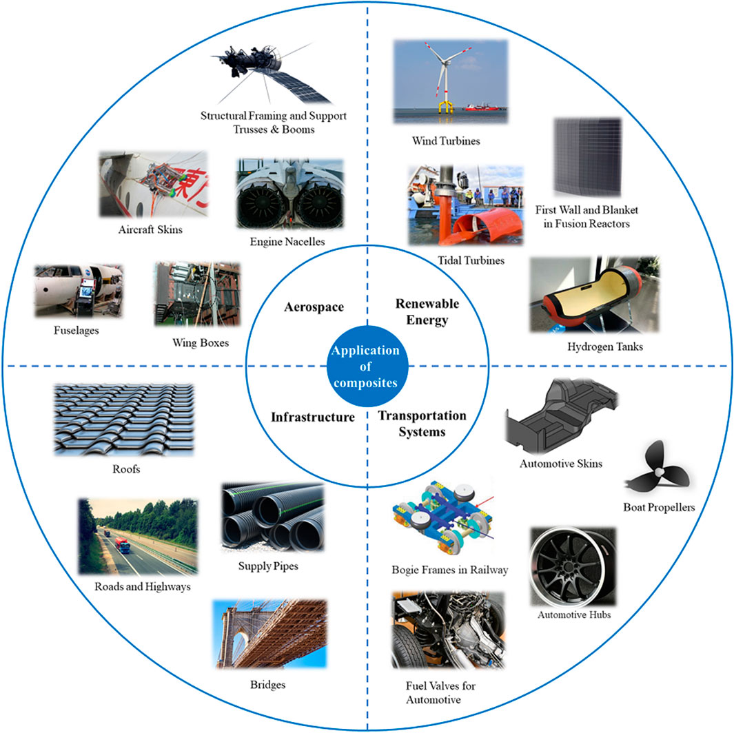
FIGURE 1. Application of composites in the areas of aerospace, renewable energy, transportation systems, and infrastructure. Photos were reproduced with permission from (Jeon et al., 2011; James et al., 2014; Martensson et al., 2017; Jiang and Wang, 2019; Towsyfyan et al., 2020; Laaouidi et al., 2021; Alves et al., 2022).
The excellent mechanical properties of FRPCs are mainly due to the integration of reinforcements in the matrix. The commonly used types of reinforcement mainly include natural and synthetic fibers. Fibers are implemented in different forms as randomly oriented, unidirectional, bidirectional, and woven mat form in the matrix (Gupta and Srivastava, 2016). Natural fibers (jute, sisal, flax banana, bamboo, etc.) are gaining increasing research interest because of their excellent cost effectiveness, low density, high flexibility, recyclability, and sustainability (Takagi, 2019). However, low impact strength and high hydrophilicity limit the further applications of natural fibers. Restrictions can be reduced by surface modification methods (George et al., 2001) or hybridization techniques (Swolfs et al., 2014). Hybrid fibers composites are materials made by combining different types or geometric aspects of fibers in the same matrix (Dong, 2018). Related studies focus on experimenting with different hybridization methods including natural/synthetic hybrid fiber composites, natural/natural hybrid fiber composites, multiple type hybrid fiber composites, and multi-scale hybrid fiber composites and have strongly proven that hybrid fiber composites provide improved properties compared with natural fiber composites (Jariwala and Jain, 2019). Synthetic fibers (glass, carbon, aramid, boron, etc.) have been widely used in aerospace, transportation, and chemical industries due to the low density and high specific strength (Hocheng et al., 1993). At present, carbon fiber-reinforced polymer (CFRP) and glass fiber-reinforced polymer (GFRP) are the most common composites materials. The CFRP has been frequently used for fabricating primary (floor and body beam, skin, wing panel, etc.) and secondary (hatch doors, fairing surfaces, rudder, etc.) structures in aircraft and can reduce the weight of the aircraft by 30% through replacing conventional aluminum alloys (Gay and Hoa, 2007). The GFRP can be used not only for military products but also for industrial and civil applications (Li et al., 2017a).
At present, the main fabrication methods of composite materials include hand layup, autoclave molding, resin transfer molding, compression molding (Al-Furjan et al., 2022), and they can be joined by adhesive bonding, mechanical fastening, fusion bonding (Irving and Soutis, 2019). As automatic composite fabrication processes, both automated tape laying (ATL) (Rodriguez-Garcia et al., 2022) and automated fiber placement (AFP) (Kumekawa et al., 2022) are commonly used for manufacturing large-size parts and have less scatter in properties than hand layup. Expensive material and equipment costs are their main disadvantages (Hanafee et al., 2019). As such, the manufacturing process of composite materials covers a series of complex procedures and each stage will introduce defects/flaws, such as poor materials handling process and impurities in the environment. FRPCs suffer from different types and scales of defects/flaws ranging from tiny fiber faults to big impact damage, which affect the overall performance and structural integrity of FRPCs, likely resulting in significant safety implications (Senthil et al., 2013a). Therefore, understanding the nature, effects, and growth prediction methods of defects/flaws is hugely significant. Effective and reliable NDT&E techniques are needed for the whole lifecycle of a composite to minimize safety concerns and maintenance costs.
In this review, we will introduce the state-of-the-art common NDT&E techniques applied to glass or carbon and other FRPCs. As the market for composite materials continues to expand, the importance of non-destructive testing of FRPCs has increasingly been demonstrated. Indeed, the detection, characterization, and evaluation of defects/flaws in FRPCs using NDT&E are quite difficult and complex due to the anisotropy and structural uncertainty (Zhou et al., 2022) of FRPCs. Also, there is a wide variety of NDT techniques built upon different principles, and most of them are complicated (Wang et al., 2020). This imposes extensive experience requirements on researchers and engineers to select one or more appropriate NDT&E techniques when performing specific defect detection on FRPCs. Thus, this article aims to provide an effective and helpful review of the most advanced progress in different NDT&E methods for the characterization and quantification of specific defects. A full description of all NDT&E methods and defects of FRPCs is beyond the scope of this article. Only the established technologies and common and high-impact defects are discussed and compared in this review.
The main body of the review is organized into Sections 2–4. Section “The primary types of defects and damage in composites” introduces and classifies the defects/flaws occurring during the whole lifecycle of FRPCs. Detailed descriptions of four more common and harmful defects including voids and porosity, fiber waviness and wrinkling, delamination and debonding, and impact damage are also presented. Section “The applications of NDT&E techniques” provides an overview of the development, principles, standard setup, and applications of the eight established NDT&E techniques. The eight NDT&E techniques involve acoustic emission (AE), ultrasonic testing (UT), eddy current testing (ECT), infrared thermography (IRT), terahertz (THz) testing, digital image correlation (DIC), shearography, and X-ray computed tomography (CT), which are divided into three categories based on the operation frequency and data processing means of the output signal that is directly under analysis. Section “The applications of NDT&E in detection and evaluation” compares and discusses the cost, testing time, benefits, limitations, etc. of each NDT&E technique. Also, an outlook on the future development of NDT&E technologies in experimental methods and data post-processing aspects is provided which may inspire the next generation of NDT&E technologies for composites.
2 The primary types of defects and damage in composites
Defects/damage have been demonstrated to occur at any time during the whole lifecycle of the FRPCs including materials processing, component manufacture, and in-service stages. According to the composition of FRPCs, some studies have systematically categorized defects as matrix, fiber, and interface/intraface defects (Irving and Soutis, 2019; Zhou et al., 2022). Matrix defects mainly include voids and porosities that arise from poor resin infusion; resin-rich regions due to uneven fiber distribution; matrix cracking caused by impact (Heslehurst, 2014). Fiber defects can be poor material layup processes that result in uneven fiber spatial distribution and misalignment of fiber orientation (Cinar and Ersoy, 2015); in-plane fiber waviness and out-of-plane fiber wrinkling arise from laminate—tool interactions (Pain and Drinkwater, 2013); fiber breakage caused by severe impact. The interface/intraface defects are mainly debonding areas between fiber and matrix; delamination between layers and debonding between adhesively bonded laminates (Senthil et al., 2013a). Figure 2 presents an overview of the categorization of various defects based on the scale level and a partial list of specific NDT&E techniques.
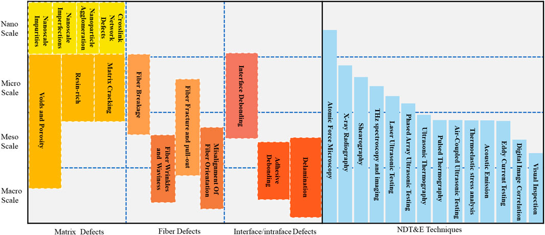
FIGURE 2. Classification of defects at different scales and the detection methods.
2.1 Voids and porosity
Voids are the most studied type of manufacturing defects due to their easy formation during the fabrication of FRPCs. The definition of voids is areas filled with trapped air or other volatiles released during curing (Park and Seo, 2011; Heslehurst, 2014).
In modern composite manufacturing processes such as out-of-autoclave curing (Kratz et al., 2013) and automated prepreg laying (Song et al., 2016), the presence of voids seriously affects manufacturing efficiency and accuracy. The generation, growth, and influence of voids during processing are not fully explained. Moreover, the use of high viscosity resins makes the problem even more complicated because it is hard to penetrate the original void spaces between adjacent fibers (Vander Voort et al., 2004). Thus, voidage has become a significant issue during the manufacturing process of FRPCs.
Voids and porosity deteriorate various mechanical properties, such as interlaminar shear strength, compressive strength, fatigue resistance, and flexural properties, which are related to mechanisms leading to a failure (Heslehurst, 2014). Evaluating the extent of degradation resulting from voids and porosity is a comprehensive function of void content, void distribution, and void shape. Porosity is strongly correlated with certain mechanical properties, and its nominal acceptance threshold for various FRPCs is 2% (Park and Seo, 2011). In detail, macroscopic voids are generated in a large zone of a matrix, mesoscopic voids between fiber bundles and microscopic voids are introduced from the inside of a fiber tow, whereas porosity is a cluster of microscopic voids.
In general, voids can be formed in different scales: macro, meso, and micro owing to the multiscale nature of composites (Mehdikhani et al., 2019). The generation of voids and porosity can be summarized as follows: 1) trapped air during preparation (Jeong, 1997) or placement of components (Huang and Talreja, 2005) (primary sources); 2) dissolved moisture or air inside a resin; 3) chemical reaction products from the resin during curing (Lundstrom and Gebart, 1994); 4) volatilization of a resin or organic inclusions at high curing temperatures (Lundstrom and Gebart, 1994).
2.2 Fiber waviness and wrinkling
Out-of-plane fiber waviness also referred to as wrinkling, is one of the major and frequently occurring defects in bulky structures and components with high thickness (Altmann et al., 2015). Fiber waviness is one common defect defined as a wave-formed ply and/or fiber deviation from a straight alignment in a unidirectional laminate (Thor et al., 2020). Over the past years, many attempts have been made to understand the mechanisms behind waviness formation. Out-of-plane fiber waviness may be divided into several groups based on the formation mechanism (Alves et al., 2021): consolidation-induced defects due to pressure deviations (Belnoue et al., 2018); bulk effect and consolidation over an external radius induced wrinkles (Dodwell et al., 2014); local compression as the material shear during forming induced wrinkles (Sjolander et al., 2016); and a combination of ply-bending and lack of interply shear (Farnand et al., 2017). The fabrication technology and processing parameters can significantly influence the formation of fiber waviness. As such, the sources of fiber waviness generation in composite materials (Kulkarni et al., 2020) during their manufacturing mainly include temperature gradient (Potter, 2009), consolidation (Pottavathri, 2015), component and tool interaction (Potter et al., 2005), as well as fiber mismatch (Marrouze et al., 2013).
The effect of fiber waviness/wrinkling on mechanical properties in FRPCs has been widely noted. The fiber wrinkles influence the mechanical properties specifically reducing their compressive and tensile strengths in the longitudinal and transverse directions (Adams and Hyer, 1994; Zhao et al., 2017). Additionally, researchers have identified that the flexural load-carrying capacity is affected due to the out-of-plane fiber waviness in FRPCs. Fatigue properties are also limited by the defect of layer waviness. For more specifics, readers can refer to (Khan et al., 2006; Horrmann et al., 2016a; Horrmann et al., 2016b).
2.3 Delamination and debonding
Laminates containing combinations of matrices and fibers are assembled to form FRPCs for the production of required material properties in different orientations. Laminates exhibit outstanding mechanical, thermal, and electrical properties in terms of geometry and structure (Steinmann and Saelhoff, 2016; Askaripour and Zak, 2019). The low transverse and interlaminar shear strength due to laminar structures are prone to produce delamination and debonding, which are two of the most frequent and dangerous failure modes in FRPCs (Bolotin, 1996; Karbhari, 2013; Han et al., 2020). Delamination is an interface/intraface defect spreading parallel to the fiber arrangement directions between laminates or within a laminate. Debonding is an unintentional separation between laminates in an adhesively bonded joint at macroscopic level.
Delamination is caused by 1) insufficient wetness of fibers or incompatible materials blended together during component preparation (Bao et al., 1992; Spearing and Evans, 1992); 2) mismatch between laminates or mishandling of components in the manufacturing process (Simanjorang et al., 2018); and 3) applied static and cyclic tensile loading or low- and high-velocity impacts during service time (Lee et al., 2006). Although delamination accompanies all of the aforementioned failure processes, it prefers to grow under compressive stress either from direct compressive loading or bending loads (Olsson, 1992; Greenhalgh, 2009). In a short time, the degradation due to delamination concentrates on accelerated damage growth and premature failure. Over time, further degradation is caused by moisture or contaminant ingress once delamination has formed (Olsson, 1992).
Adhesive bonding is an advantageous connection method, which has been used for joining primary composite structural components in aerospace and automotive structures. Different from mechanical joints which have stress concentrations around fastener holes, the stresses in adhesive bonding are distributed over the entire bond area (Senthil et al., 2013a). Debonding is discrete regions where the composite joint is not bonded together that arises from manufacturing issues, presence of entrapped air or damages during services (Senthil et al., 2013b). Under compressive loading, the growth and expansion of debonding can lead to joint failure at stress levels well below the material capability and finally affect the performance of structures.
More specific studies on delamination and debonding failure modes of FRPCs can be found in (Kim, 1997; Kim and Kwon, 2004; Wang et al., 2005; Meng and Wang, 2015).
2.4 Impact damage
Impact damage is a frequent and complex feature consisting of randomly distributed median and lateral cracks and overlaying delamination of different sizes and shapes (Rus et al., 2020).
Most of the impacts on a composite structure will occur in the transverse direction. Owing to the vulnerable interface strength in the thickness direction (Jawaid et al., 2018; Wronkowicz-Katunin et al., 2019), FRPCs are prone to failure of various modes including visible (dents, fracture, crushing, etc.) and invisible (delamination, debonding, cracks, etc.) impact-induced damage which severely reduces the integrity and durability of composites structures (Agrawal et al., 2014). FRPCs are susceptible to impact damage during manufacturing and service time, which restricts the safe utilization of composite materials.
Many researchers have classified impact damage, but there is not a clear transition between categories. Typically, impact damage is classified as low-velocity impact (LVI), high-velocity impact, and hyper velocity impact based on the speed of impact. Sjoblom et al. (1988) defined LVI to be within the range of 1–10 m/s depending on the target stiffness, material properties, and the impactor mass. Razali et al. (2014) summarized that LVI occurs at speeds below 11 m/s and may be caused by dropped tools during maintenance operations. Irving and Soutis (2019) defined LVI as events that can occur in the range of 4–10 m/s with energies up to 50J. While high-velocity impact arising from ballistic impact occurs in the range of 300–2,000 m/s and 10–20 kJ. Moreover, hypervelocity impact usually refers to the impact of space debris on a spacecraft at velocities on the order of 30–70 km/s.
Herein, we mainly focused on LVI damage, which can be loosely described as impact at low speeds. LVI damage may not have any damage indication on surfaces by visual inspection but may have already occurred inside the structure (Zhang and Richardson, 2007). Thus, the damage is known as barely visible impact damage (BVID), which significantly affects the properties of composites. Normally, LVI produces indentation on a surface, interlaminate delamination, intralaminates cracks, and finally fiber breakage at the bottom if impact is critical. The formation of BVID is attributed to compression and interlaminar and intralaminar shear stress that exceeds the tolerance limitation once impact occurs (Davies and Zhang, 1995). The specifications and requirements of BVID have been modified to quantitively evaluate the damage in aircraft manufacturing fields (Talreja and Phan, 2019). The BVID is defined as “small damages that may not be found during heavy maintenance general visual inspections using typical lighting conditions from a distance of 5 feet” (Fawcett and Oakes, 2006) for the Boeing 787 composite airframe. According to the associated probability of detection, Airbus defines BVID as detectable damage with 90% probability with a confidence interval of 95% (Fualdes and Morteau, 2006). Usually, the dent depth for BVID is set at 0.3 mm after considering relaxation and the method of inspection (Fawcett and Oakes, 2006). Many other standards have been reported regarding the specification, definition and quantitative assessment of BVID, including ASTM-D7136, EASA CS 25.571, and Airbus AITM-1.0010 (Sun and Hallett, 2017; Irving and Soutis, 2019).
2.5 Simulated defects
For all types of NDT&E technologies, the validation and calibration of the techniques by the characterization of the defects/damage are indispensable parts. Simulated defects are frequently utilized to develop representative NDT&E standards as known defects. Based on a standard, the size, shape, and depth of the detected defects by an inspection technique can be compared with the simulated defects quantitatively. The assessment can determine the effectiveness and limitation of NDT&E technologies and guide the corresponding calibration to meet testing requirements. Importantly, the design, selection, and manufacture of simulated defects must be able to represent the relevant characteristics of real defects to obtain an accurate assessment. Moreover, simulated defective samples are utilized to establish standard samples, which reduce the time to calibrate technology and reduce costs. These also help the trainees to gain experience with realistic samples and will reduce the variability between inspectors (Dayal et al., 2018).
Simulated defects in FRPCs are usually associated with interface/intraface defects and impact-induced damage. Thin bagging film with a thickness below 13 μm is commonly used to simulate delamination between two laminates in composite in fracture mechanics test standards (Juarez and Leckey, 2018). The film should have the properties of low adhesion material and high tensile strength to be easily separated from the epoxy resin and pulled out of the composite without a tear (Bahonar and Safizadeh, 2022). The main materials used to simulate delamination and debonding include Teflon (polytetrafluoroethylene (PTFE)), ethylene-propylene fluoride (FEP), Mylar polymer films. Among them, Teflon is the most commonly used material (Montinaro et al., 2018). Some researchers have also used flat-bottom holes (FBHs) to simulate delamination at different depths (Junyan et al., 2015; Kalyanavalli et al., 2018). Furthermore, simulation of impact-induced damage is relatively easy, usually using impactors to impact the composite at different energies.
The detection and evaluation of simulated defects help to calibrate the parameters and setups of NDT&E methods. (Bang et al., 2020). utilized a dataset of thermographic images of composite materials with simulated impact surface damage to verify and improve the deep learning system reliability. In composite defect detection using air-coupled ultrasonic (ACU) testing, a simulated delamination is also used to provide datasets for a support vector machine (SVM) classifier to improve delamination identification accuracy (Bahonar and Safizadeh, 2022). Additionally, (Maierhofer et al., 2014), proposed to compare the ability of flash thermography using reflection and transmission configuration by assessing a simulated delamination in stepbar CFRP samples. The results demonstrated transmission configurations have better lateral damage area evaluation accuracy and worse depth detection capability than reflection configurations, which contributes to the improvement of transmission testing systems.
Simulated defects are also significant for quantitatively evaluating and finding the limits of NDT&E technologies. Probability of detection (PoD) analysis as a quantitative measure is widely used to evaluate the inspection reliability of traditional NDT&E techniques (Ahmad, 1989; Muller et al., 2006). As a statistical method, PoD requires a large number of samples having defects ranging from non-detectable to minimum detectable sizes and larger (Peeters et al., 2018). Duan et al. (2019) utilized PoD analysis to compare the obtained inspection results for a set of impacted CFRP plates by employing UT and pulsed thermography testing (TT) approaches. The result indicated that thermography testing has a smaller defect size (∼11.43 mm) at 90% PoD with 95% confidence level than UT (∼16.2 mm). A CFRP sample with a simulated delamination was detected and evaluated by PoD analyses of line scan thermography (LST) (Peeters et al., 2018). Delamination simulated by Teflon inserts has lateral sizes ranging from 3 to 15 mm placed between each consecutive ply at different depths. The detection rate is less than 28% to detect the delamination on larger depths (>1 mm) and higher than 84% for the very shallow defects of 0.2–1 mm. For some other studies on quantitative analysis of detection techniques using simulated defects in FRPCs, the reader is referred to (Yang et al., 2013; Junyan et al., 2015; Kalyanavalli et al., 2018; Sun et al., 2019).
3 The applications of NDT&E techniques
NDT&E means a wide range of analytical technologies used to test, characterize or evaluate the properties of a material, component, or system for characteristic differences or defects and discontinuities without causing damage (Cartz, 1995). NDT&E technologies are utilized during or after fabrication process and on FRPCs products in service. During the manufacturing stages, the application of NDT&E technologies determines the quality of the product and its lifetime before failure. During the service stages, NDT&E technologies are used to inspect arising defects/damage and evaluate the structural properties for safety in service. As an integral part of the structural health monitoring (SHM) system, NDT&E technologies also contribute to monitoring the damage development and estimating remaining life. Each technique has a unique detection potential and does not allow a full evaluation of defect information and the damage state of the material (Duchene et al., 2018). Thus, choosing one or several combined suitable NDT&E technologies according to different conditions is very important. The considerations can be mainly classified into defect/damage conditions (type, location, shape, size, etc.), testing requirements (the accuracy, speed, and cost of detection), and detectability of NDT&E technologies (the penetration, sensitivity, resolution, contrast and the subsequent limitations of the NDT&E method under consideration).
Any classification of NDT&E techniques is quite difficult due to many criteria and considerations involved. There are several common methods to classify NDT&E techniques into different groups such as the way a test is conducted, the position of measuring sensor relative to the surface of composite material being tested, the safety issues of the inspection site, and the type of output signal involved (Nsengiyumva et al., 2021). Among them, the classification based on the type of output signal involved as the signature of each NDT&E technique is often attempted by researchers and engineers (Garnier et al., 2011; Askaripour and Zak, 2019). NDT&E techniques utilize the variable portions of a frequency spectrum of output signal to detect and characterize defects (Gupta et al., 2021). Based on the operation frequency and data processing means of the output signal that is directly under analysis, NDT&E techniques can be divided into three categories: acoustic wave-based NDT&E, electromagnetic techniques-based NDT&E, and imaging techniques-based NDT&E, as shown in Figure 3.
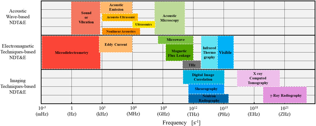
FIGURE 3. Classification of different NDT&E technologies in the frequency domain.
3.1 Acoustic wave-based NDT&E
Acoustic wave-based NDT&E utilizes different modes of emitted energy emissions to a composite sample, and the received acoustic waves from reflection, refraction, scattering and transmission are investigated to identify and detect defects/damage. As typical acoustic wave-based NDT&E technique, acoustic emission and ultrasonic testing are discussed in this section.
3.1.1 Acoustic emission
AE is a physical phenomenon of radiation of acoustic (elastic) waves in solids caused by the rapid release of internal energy from a localized source or sources within a material (Zhang et al., 2012; Barile et al., 2020). AE measurement is utilized to detect elastic waves produced by the damage in the tested composites through arrays of highly sensitive transducers. Therefore, unlike UT, AE testing is a passive, receptive and dynamic technique to receive the acoustic signal at the moment of defect occurrence. Figure 4A illustrates the schematic of a typical AE system setup. Thus, AE technology can monitor and sense defects such as fiber breakage, matrix cracking, debonding, and delamination based on the analysis of released elastic waves (Hamstad, 1986). The development of AE technology began in the early 1950s when Kaiser discovered the AE phenomenon in the deformation process of metals such as steel, copper, and lead (Kaiser, 1950). AE-based NDT&E technique can be detected in frequency ranges from several Hz infrasonic waves to several MHz ultrasonic waves, but most of the released energy is within the 1 kHz to 1 MHz range. The main applications of AE-based NDT&E technique are focused on source location (Li and Yan, 2013), structural defect detection (Liu, 2021), and health monitoring (Romhany et al., 2017).

FIGURE 4. Schematic of system setups: (A) a typical AE system setup; (B) a UT system setup with immersion detection.
In AE monitoring of FRPCs, the researchers have attempted to investigate microscopic damage mechanisms by focusing on AE signal parameter analysis (Guo et al., 2013) such as AE signal amplitudes, rise time, decay time, characteristic frequency, etc. Defects like microcracks in the matrix, debonding, and fiber breaks in laboratory-scale test specimens have different signal amplitudes or other AE signal magnitude parameters (Awerbuch, 1997) which can be used to identify damage mechanisms. However, the approach ignores the high signal attenuation of composite materials and cannot provide a clear separation between different mechanisms (Gresil and Giurgiutiu, 2015). An alternative for evaluating damage mechanism is the analysis of AE waveforms and power spectra (intensity and frequency) obtained by Fast Fourier Transform (FFT) from AE signal. Because the determination of dominant frequencies of the signal can be used to characterize each acoustic event which is directly related to main failure mechanism (Ramirez-Jimenez et al., 2004). However, frequency analysis may only work for a specific type of specimens (often laboratory-scale) and the results are usually not transferable to other types or sizes of composite structures. Arumugam et al. (2014) tested the AE signal from
The location accuracy of AE signal source location has been proven to allow for SHM with AE (Romhany et al., 2017). Zhou et al. (2011) proposed a hybrid detection method for fatigue damage using acousto-ultrasonic (AU) wave which is combined with ultrasonic characterization and acoustic-emission. The method has become one of the prevailing tools to develop SHM. Jung et al. (2022) utilized a, b-value parameter for quantitatively monitoring the structural health of CFRP based on the AE signals. The composite b-value represents the amplitude distribution slope of the AE signals and reflects the attenuation rate for SHM of composite materials. By analyzing the AE signals of a series of plain woven CFRP samples under different cyclic loading conditions, the results have provided a structural health criterion based on the composite b-value.
In summary, AE signals have been utilized to monitor and locate cracking, delamination, and/or adhesive bond failure at the interfaces in FRPCs. AE has a long history of successful SHM applications mainly for storage tanks and pressure vessels and is also promising for SHM of complex composite materials and structures. With the advantages of fast detection speed and low labor intensity, AE can be performed without a service shutdown of the structure in many cases (Dong and Ansari, 2011).
3.1.2 Ultrasonic testing
To detect defects and damage, UT utilizes transducers to generate ultrasonic waves that in turn propagate into composite laminates. This technique covers a wide frequency spectrum (from 1 MHz to above 1 GHz) but the most industrial UT applications with frequencies are ranging from 0.5 to 10 MHz in FRPCs (Duchene et al., 2018). Also, frequencies lower than 0.5 MHz can be used in FRPCs, such as lamb wave inspection of defects/damage in composites (Tong et al., 2022). The elastic waves propagating in a medium can be categorized into volume waves, surface waves and guided waves. Internal defect information is obtained from the reflection, transmission, and backscattering of pulsed elastic waves mainly received by two ways: pulse-echo and through-transmission (Rao et al., 2019). A pulse-echo mode requires only one side to transmit and receive ultrasonic waves and detect samples, whereas a through-transmission mode involves the emission and reception of ultrasonic waves from each side of a sample. Therefore, only one transducer can be used for pulse-echo while trough transmission needs two. Moreover, pitch-catch is another useful way to get the reflected echo applied on only one surface of the structure with two transducers (Park et al., 2012). Schematic of a UT system setup with immersion detection is shown in Figure 4B. Depending on the transducer used, UT can be mainly classified as piezoelectric transducers (Cui et al., 2022), air-coupled transducers (ACT) (Liu et al., 2013, Liu et al., 2014), phased array ultrasonic transducers (PAUT) (Rizwan et al., 2021; Zhang et al., 2021), and electromagnetic acoustic transducers (EMAT) (Gao et al., 2010; Strass et al., 2017). However, EMAT transducers require a specific set-up to work on electrically non-conducting materials such as polymer composites. Various operating modes are involved mainly including A-scan (amplitude-time representation), B-scan (amplitude image of a unidirectional scanning), C-scan (amplitude image of bidirectional scanning), D-scan (time-of-flight image of bidirectional scanning), and so on (Nsengiyumva et al., 2021).
The capability of UT to qualitatively and quantitatively characterize and evaluate composite defects and damage has been demonstrated over the past many years. The C-scan method of UT is a very significant and extensive NDT&E technique. The brief principle of the method is to process and map pulse-echo or transmission signal onto a plane view of the tested component to obtain information on the size and depth of defects/damage. Immersion ultrasonic C-scans are used in measuring delamination extent for impact-induced damage in the form of double-through transmission and pulse-echo (Fromme et al., 2018). Due to waves not being well transmitted through delamination, double-through transmission shows the delamination area with consistently low amplitude in Figure 5A. While for the pulse-echo case, the delamination area is displayed as an increased reflected signal in Figure 5B because of the shorter distance traveled compared to reflection from the opposite surface. Ellison and Kim (2020) developed a method to reduce the delamination shadowing effects and estimate the full delamination state at a damaged interface by utilizing C-scan to obtain layer-by-layer delamination information from an impacted 24-ply unidirectional CFRP. Alarifi et al. (2019) utilized A-scan and C-scan of UT to examine FRPC materials with different levels of porosity. They succeeded in obtaining the porosity content and depth information by C-scan and its histogram and A-scan data, which conformed with the destructive testing (DT) results. The loss of the sound signal reflected as the dB loss in the histogram image has demonstrated the relationship with porosity. Original dB loss is close to being proportional to the imaging void content. Moreover, C-scan of UT has also been used to evaluate the artificial defects (Hasiotis et al., 2011), cracks caused by thermal stress (Shiino et al., 2012), debonding defects (Patronen et al., 2018) of composite materials and structures.
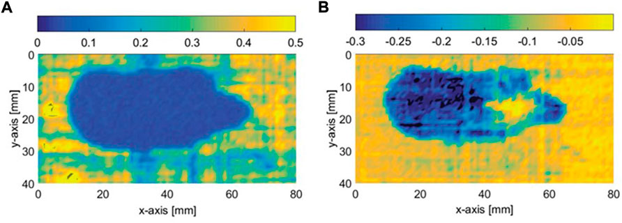
FIGURE 5. Color-coded ultrasonic C-scan images of impact-indued damage CFRP specimen with thickness of 2 mm: (A) double-through transmission; (B) pulse reflection (Fromme et al., 2018).
PAUT is a powerful UT technology due to its flexible beam deflection and focusing characteristics through beam forming (Taheri and Hassen, 2019). Taheri and Hassen (2019) utilized bulk wave and guided wave to detect the artificial hole with different diameters and depths in CFRP by using PAUT and single-element (conventional) ultrasonic signals (SEUT). The results indicated that both PAUT and SEUT can detect the hole with a minimum diameter of 0.8 mm and a thickness of 25 mm while signals of PAUT have better characteristics. Zhang et al. (2021) proposed an efficient and accurate method to detect out-of-plane waviness in hybrid glass–carbon FRPCs plates using PAUT with 5MHz and 32 elements. Samples with different waviness angles were used for the experiments. The results were discussed quantitatively that the relative errors in maximum waviness angle for samples are 4.6% and 14.8% by comparing images from PAUT results with optical methods. PAUT has also been proposed to quantitatively estimate the location, size, and morphology of impact-induced damage in CFRP specimens with different impact energy (Caminero et al., 2019; Cao et al., 2020).
Additionally, there are many other useful UT technologies including ACU, laser ultrasonic testing, ultrasonic infrared thermal imaging technique, fiber ultrasonic testing, etc. ACU is non-contact testing and utilizes ACT to excite and receive ultrasonic waves to detect defects/damage in materials and structures (Chen et al., 2021). ACU has been progressively used in aerospace industry (Li and Zhou, 2019) to inspect large parts that cannot be coupled with liquids, such as helicopter tail booms (Ma and Zhou, 2014), rotor blades (Peters et al., 2004), etc. fabricated by FRPCs. Laser ultrasonic testing uses ultrasonic waves, excited inside the material by laser-induced thermal stress, to detect flaws without contact. Laser ultrasonic testing technology is especially suitable for rapid automatic detection of large and complex structures (Dubois and Drake Jr, 2011; Zhou et al., 2018; Qiu et al., 2020). EMAT can be used in the in-line inspection of the joint quality of composites during joining or immediately after joining (Strass et al., 2017).
In summary, UT has been utilized to qualitatively and quantitatively detect, characterize, and evaluate various defects/damage in FRPCs. UT plays an essential role in FRPCs defect detection and has become the hot spot and focus direction of composite material detection. For more details on the application of UT technologies, Table 1 summarizes the application of UT techniques with different classifications in the detection and evaluation of defects in composite materials. Predictably, UT will be further applied to achieve the visualization, automation, and intellectualization of defect detection and evaluation.
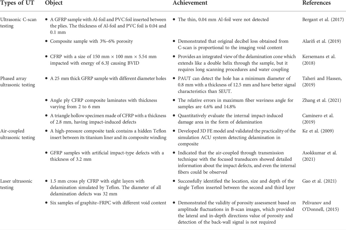
TABLE 1. Summary of typical types of UT applications for the detection and evaluation of FRPCs.
3.2 Electromagnetic techniques-based NDT&E
Electromagnetic techniques-based NDT&E utilizes an electric current, magnetic field, or both to induce a response from a composite sample, and the received electromagnetic response is investigated to identify and detect defects/damage. Some of the most useful electromagnetic techniques-based NDT&E, including eddy current testing, infrared thermography, and terahertz testing are discussed in this section.
3.2.1 Eddy current testing
ECT is an efficient and non-contact electromagnetic-based NDT&E technique for the characterization of the surfaces and sub-surface flaws in conductive materials. In this method, eddy currents are generated in the conducting sample when the test coil with an alternating current is close to the conducting sample. Figure 6A shows the schematic of an ECT system setup with a theta probe. The change of eddy current in the conducting sample due to the presence of defects, damage, or inclusion in the sample is monitored as change of impedance of the test coil or another detecting coil (De Goeje and Wapenaar, 1992). Commonly, CFRP is composed of many unidirectional carbon fiber/epoxy plies stacked in a certain sequence. The conductive carbon fibers in CFRP are separated from each other by insulated polymer. However, CFRP is capable of conducting current in certain directions via the electrical networks formed by carbon fibers and contact points (Cheng et al., 2016). Therefore, ECT method has a potential to map the fiber feature and inspect the defects in CFRP.
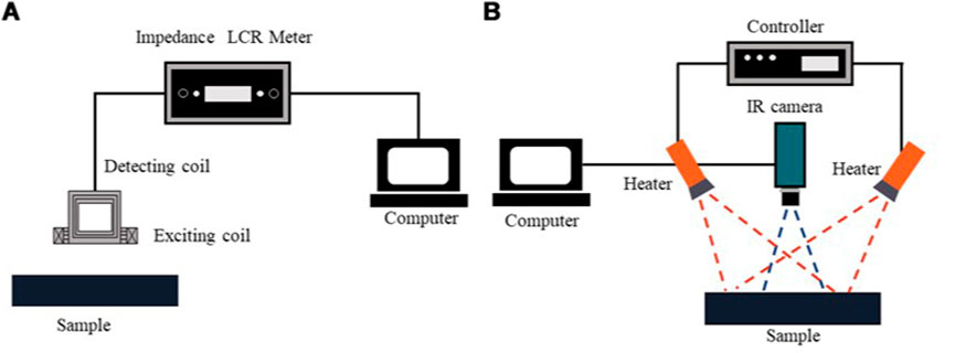
FIGURE 6. Schematic of system setups: (A) a ECT system setup with a theta probe; (B) an IRT system setup.
The correct selection of probe shape and signal processing method is essential for the application of ECT for CFRP defects/damage detection (De Goeje and Wapenaar, 1992; Lange and Mook, 1994). A cross point (CP) probe with a rectangular exciting coil in the upright position has been proposed to inspect defects in CFRP using ECT (Koyama et al., 2013). Three samples with different fiber directions via woven CFRP, unidirectional CFRP, and quasi-isotropic CFRP were experimented with to detect the simulated defects. The thickness of all three CFRP samples was 3 mm. Simulated by unidirectional composite fibers, the electrically insulated defects with thicknesses of 1.0 mm were inserted at a depth of 1 mm from the surface of the samples. The CP probe can adjust the positioning of the exciting coil based on the fiber direction of the plies. And the conclusion was demonstrated that simulated defects in woven CFRP and unidirectional CFRP could be inspected with little noise under the experimental conditions. Similarly, ECT technique was proposed to inspect surface defects of CFRP by utilizing rectangular differential probe (Wu et al., 2014). Two
Eddy current thermography is an emerging and prospective NDT&E technique, which combines the advantages of conventional eddy current testing and thermal testing. Eddy current pulsed thermography (ECPT) has been successfully investigated and characterized for surface crack evaluation in CFRP (Cheng and Tian, 2011). The width and depth of crack notch can be determined based on the amplitude of the temperature rise, heating and cooling thermal response. The delamination detection in CFRP laminates was conducted by utilizing ECPT with a 20-layered CFRP sample (Cheng and Tian, 2012). Two-layered polytetrafluoroethylene film (of thickness 0.1 mm for each layer) was used for simulated defects inserted at different thicknesses. The results indicated that ECPT is not able to detect delamination up to 930 μm in-depth. With more powerful excitation: pulse width, inductor geometry, and directions for ECPT, ECPT will be able to detect deeper delamination. ECPT was also used to characterize the impact damage of 12 layers woven CFRP at different impact energies (12-2J) (He et al., 2014). The areas of impact-induced damage are drawn at the thermograms in the form of hot areas and only 2 J and 4 J impacts cannot be detected.
In summary, ECT has been applied to detect various types of surfaces and sub-surface flaws like cracks, delamination, and fiber damage at high inspection speeds, high SNR ratios and provides some indication of the extent of damage via signal amplitude. Therefore, ECT is also a promising technology of SHM for composites. However, further development of the ECT probe is required for the inspection of highly anisotropic CFRP materials and CFRP with complex fiber arrangements.
3.2.2 Infrared thermography
IRT is an NDT&E technique that measures defects based on structural response from either thermal energy dissipation or temperature increased by thermoplastic or thermoset characteristics of matrix (Boccardi et al., 2014; Heslehurst, 2014). The principle of IRT is that the thermal properties of different materials including a host structure and embedded discontinuities cause a change in thermal radiation, the range of which is located at the infrared area of the wavelength spectrum in most applications (Askaripour and Zak, 2019). IRT is classified as passive infrared thermography (PIRT) or active infrared thermography (AIRT). PIRT methods identify internal defects by acquiring the thermal radiation of a specimen’s surface without employing external heat. While AIRT methods apply energy sources to a specimen’s surface for defection to increase inspection accuracy and reduce the influence of environmental noises (Hung et al., 2009). According to the excitation source, the AIRT can be generally divided into optical excitation thermography (noncontact pulsed, step, and lock-in thermography), ultrasonic mechanical excitation thermography, cycled loading excitation thermography, eddy current excitation thermography, etc. (Favro et al., 2001; Montanini, 2010; Liu et al., 2016). Figure 6B shows an IRT system setup in reflection mode.
IRT has been demonstrated to be an effective way to detect and quantify the subsurface damages in FRPCs (Maldague, 2001). In the past decades, the applications of IRT in the detection and evaluation of defects in composite materials have been extensively explored. (Toscano et al., 2014). presented lock-in thermography for the monitoring of delamination propagation in situ during a compressive mechanical test and successfully observed delamination buckling and growth. (Montanini and Freni, 2012). have quantitatively evaluated the ability of optically excited lock-in thermography (OLT) to detect depth of simulated delamination in GFRP. For deep layer damage, using OLT as a second inspection seems to be a useful method when the back surface is accessible. (Gaudenzi et al., 2014). examined delamination by using ultrasound and pulsed thermography. Comparison with the PAUT results has demonstrated the effectiveness of pulsed thermography in delamination detection. However, pulse thermography is less effective in determining the area of delamination with different energy levels than UT. When detecting relatively deep defects, pulse thermography exhibits a remarkable underestimation of the damaged area (Papa et al., 2020). Pulses of pulsed thermography must be limited to avoid damaging the structure, thus pulsed thermography is not suitable for testing thick composite materials (Balageas, 2012). Step heating thermography has been proposed to overcome some limitations of pulsed thermography (Ghadermazi et al., 2015). The method uses a long pulse of low-power heat excitation to identify defects that are 0.5–2 mm deep in thick FRPCs. All the defects were detected through the Fourier image processing, except the defect with a depth of 2 mm.
Thermoelastic stress analysis (TSA) has been used as an effective NDT&E tool for evaluating the defects of adhesive areas in CFRP (Pitarresi et al., 2019; Palumbo et al., 2021; Tuo et al., 2022). In TSA, a tested sample is usually subjected to a cyclic tensile loading within the elastic region of the sample (Tighe et al., 2016). The good capability of TSA for the detection and evaluation of debonded areas in CFRP T-joints made by the AFP process (Palumbo et al., 2021) has been quantitatively demonstrated in the article. The results also showed that TSA is more sensitive to “kissing bond” defects than lock-in thermography. In another research, the TSA ability to inspect adhesive damage in lap joints was demonstrated to be beneficial for long-term fatigue tests or comparing the mechanical performance of various FRPCs joints (Johnson, 2014). (Katunin et al., 2021) used vibro-thermography to investigate voids, which exist in composite disks in the form of lower-density areas. The excitation of vibro-thermography was mechanical vibrations provided by an electrodynamic shaker with a frequency equal to the natural frequency at maximum vibration amplitude. The results demonstrated that vibro-thermography is unsuitable for tiny void defects in composite disks. Due to the high stiffness properties of composite materials, the response of mechanical excitation was extremely small, which reduced the sensitivity and resolution to voids. Nevertheless, vibro-thermography as a noncontact method was found to be effective in detecting defects of composites with complex geometry. In the comparison with pulsed thermography, ultrasonic thermography has been proven to be more suitable for detecting tiny damage, such as small joint delamination, matrix cracking, and fiber breakage in impact-induced CFRP (Li et al., 2016). While pulsed thermography is more suitable for detecting large delamination damage.
In summary, IRT has successfully proven the capability of detecting delamination and debonding, impact-induced damage, voids, and fiber-matrix cracking in composite materials and structures. Table 2 gives more information about the detection and evaluation of different defects in FRPCs by using IRT.
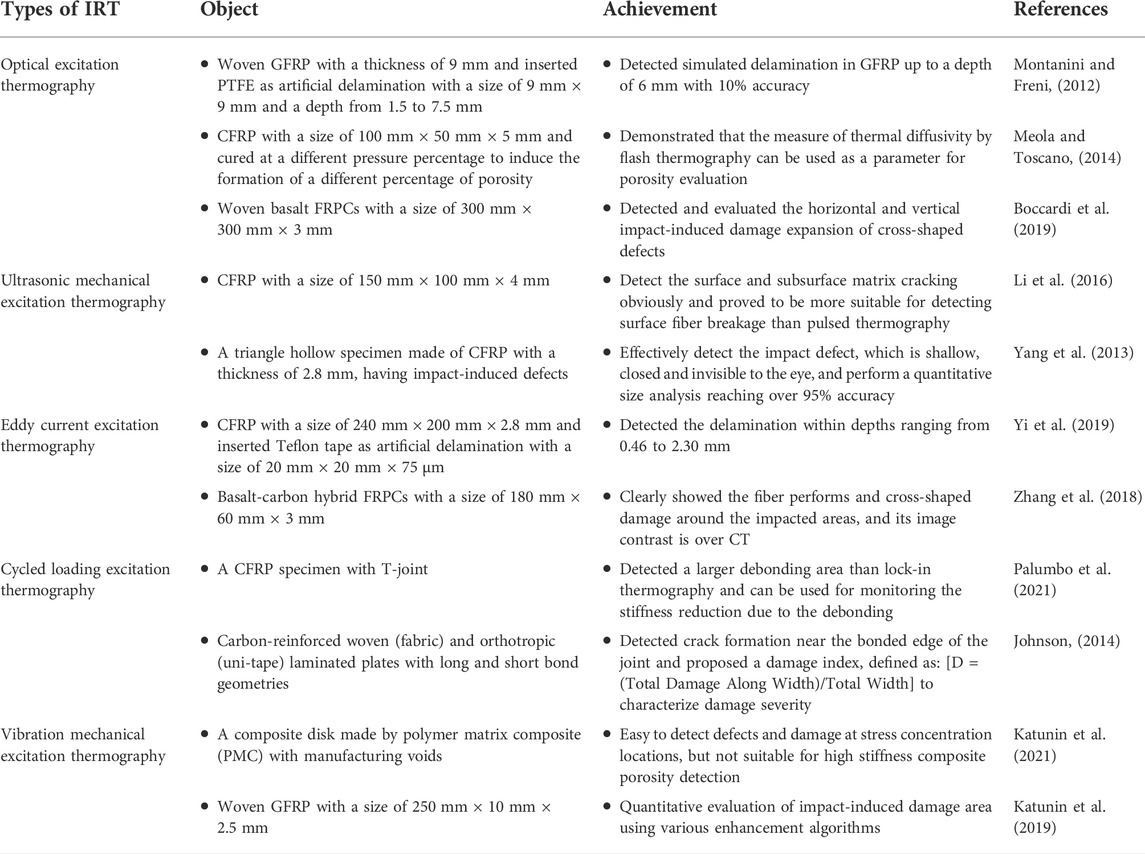
TABLE 2. Summary of typical types of IRT applications for the detection and evaluation of FRPCs.
3.2.3 Terahertz testing
THz waves are electromagnetic waves in the frequency band between 0.1 THz and 10 THz and electromagnetic wavelength is accordingly between 30 μm and 3 mm (Besson and Minasyan, 2017). THz waves have the special property of being able to penetrate a wide variety of non-conducting materials such as ceramics, glass, polymers, rubber, and composites. As an emerging NDT technique, THz-based NDT&E technology has demonstrated its effectiveness in the inspection of delamination in FRPCs (Destic et al., 2010), debonding in the adhesive layer of thermal protection material (Karpowicz et al., 2005), impact damages on composite laminates (Destic and Bouvet, 2016), etc. The THz system utilizes short THz waves to interact with defects/damage in composites. The internal features of composite materials are identified by evaluating the reflected or transmitted THz waves (Zhong, 2019). The Schematic of terahertz time-domain spectroscopy (THz-TDS) system setup for a composite sample is illustrated in Figure 7.
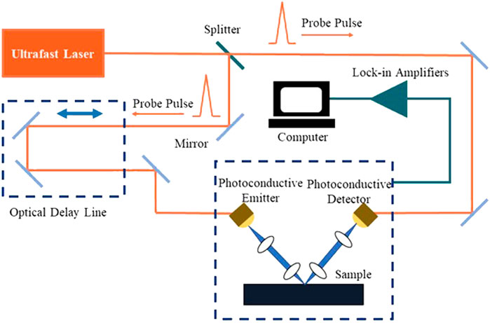
FIGURE 7. Schematic of a THz-TDS system setup for a composite sample.
As another electromagnetic technology, THz waves can penetrate dielectric materials quite easily but not electrically conducting materials (Hsu et al., 2012). For GFRP, THz waves have been used to characterize both flaws and material parameters, such as voids (Stoik et al., 2010), delamination (Dong et al., 2016a), and fiber orientation (Jordens et al., 2010). Simulated multi-delaminations made of Teflon film with a thickness of 0.15 mm in GFRPs have been successfully visualized by utilizing THz spectroscopy system in B- and C-scans (Han and Kang, 2018). The thickness of GFRPs specimen was 0.8 mm. In Figure 8, a hidden multi-delamination has been shown in THz transmission C-scan visualization images with different maps. Quantitative thickness information about multi-delamination is calculated using the reflection of THz waveforms. The results shown in B-scan images have demonstrated a close consistency compared with the practical value (<3.7% error). Moreover, THz is a promising tool for the high-resolution electromagnetic detection and evaluation of internal voids or delamination masked by the presence of water in marine GFRP, which may be difficult for acoustic methods to inspect (Ibrahim et al., 2021). THz has been utilized for the detection of damage and water ingress in thick woven GFRP (Chulkov et al., 2015). The volumetric defects in moist GFRP laminates were successfully detected and indicated that THz has the potential for water detection in the honeycomb panels of aircraft.
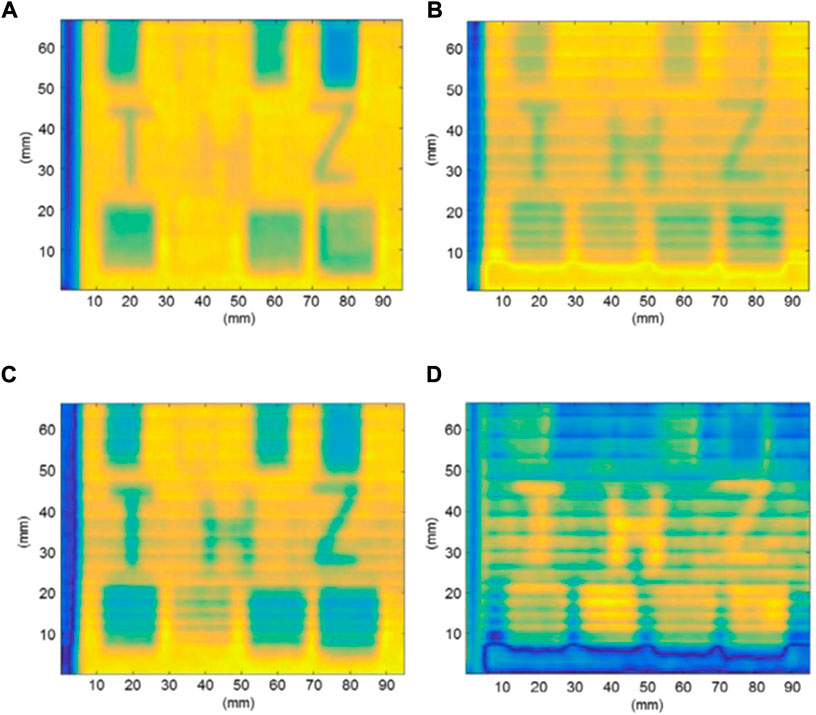
FIGURE 8. THz transmission C-scan visualization images obtained at 0.225 THz: (A) magnitude map; (B) phase map; (C) real-component map; (D) imaginary-component map (Han and Kang, 2018).
CFRP is a poor conductor with anisotropic conductivity. Therefore, quantifying penetration of THz on CFRP is significant for defect detection assessment. In 2012, (Hsu et al., 2012), demonstrated that THz pulses can penetrate through approximately 100 mm of the CFRP laminates with a frequency range of 0.1–1 THz. Polarization-resolved THz technique has been demonstrated to significantly enhance the THz radiation imaging on woven CFRP laminates (Dong et al., 2016b). By taking advantage of THz C-scans, two samples with thickness of 2.4 mm were investigated under different static loading types (Dong et al., 2018). Different subsurface damage categories, including matrix cracking, fiber distortion and fracture, and intra-ply delamination have been successfully characterized by utilizing polarization-sensitive THz imaging method. Thus, THz has great potential to evaluate the damage mechanisms of woven CFRP as a complementary NDT&E method. To quantitatively evaluate the ability of THz technique for subsurface defect detection in CFRP, reflective THz time-domain spectroscopy (THz-TDS) system and vibro-thermography (VT) system were implemented for inspection of impacted CFRP specimens in the study (Xu et al., 2020). The thickness of CFRP specimens was 1.0 mm and the impact energies are ranging from 5 J to 25 J. The THz and VT result images were compared with the same resolution 350 × 350 pixels. The criterion of threshold to distinguish defective and non-defective regions was 3 times the standard deviation, i.e., 3σ. In this way, the results indicated that THz has a similar damaged areas ratio with the VT under 5J energy impact while much smaller results at 15J and 25J than VT. The quantitative comparison showed that VT is advantageous in detecting deeper defects while THz imaging exhibits more details on subsurface defects.
In summary, THz testing constitutes an effective method for the NDT&E community to inspect and characterize defects/damage in composite materials and structures. THz waves can be utilized to characterize both surface and underlying defects/damage, including mechanical/heat damage, voids, delamination, intrusions, and moisture contamination (Dong et al., 2018). THz is undoubtedly a promising approach for imaging compared with other established NDT&E techniques, due to its good ability to penetrate nonpolar objects and low radiation energy. Composites reinforced by non-conductive fibers, such as glass and ultra-high molecular weight polyethylene (Palka et al., 2016) have been successfully characterized via THz imaging. Furthermore, THz imaging studies of CFRP have also been greatly developed.
3.3 Imaging techniques-based NDT&E
Imaging techniques-based NDT&E utilizes the difference between the images obtained before and after a given time/deformation to highlight defects or changes in defects. Some of the most popular imaging techniques-based NDT&E, including digital image correlation, shearography, and X-ray computed tomography are discussed in this section.
3.3.1 Digital image correlation
DIC is a non-contact optical image technique for measuring strain and displacement. During the deformation of the detected composite structures (Molland and Turnock, 2021), the DIC system utilizes the digital camera to record a series of surface images on which a randomized speckle pattern is applied, as shown in Figure 9A. The deformation and strains of the investigated object can be determined based on the comparison of two images (without and under mechanical loading or under two different mechanical loading) corresponding to the flat surface of the object (Broughton, 2012). Digital systems are available to allow the real-time measurement of full-field two-dimensional (2D) or three-dimensional (3D) deformation vector fields and strain maps. The operating range of DIC systems is from the micro-scale to the macro-scale (μm to 10 m) (Broughton, 2012). The numerical range of a pixel (gray-level resolution) and the number of pixels are two parameters that influence the accuracy of the captured images in the DIC technique (Bosch et al., 2019). With higher pixel gray-level resolution and pixel count, image accuracy can be improved.
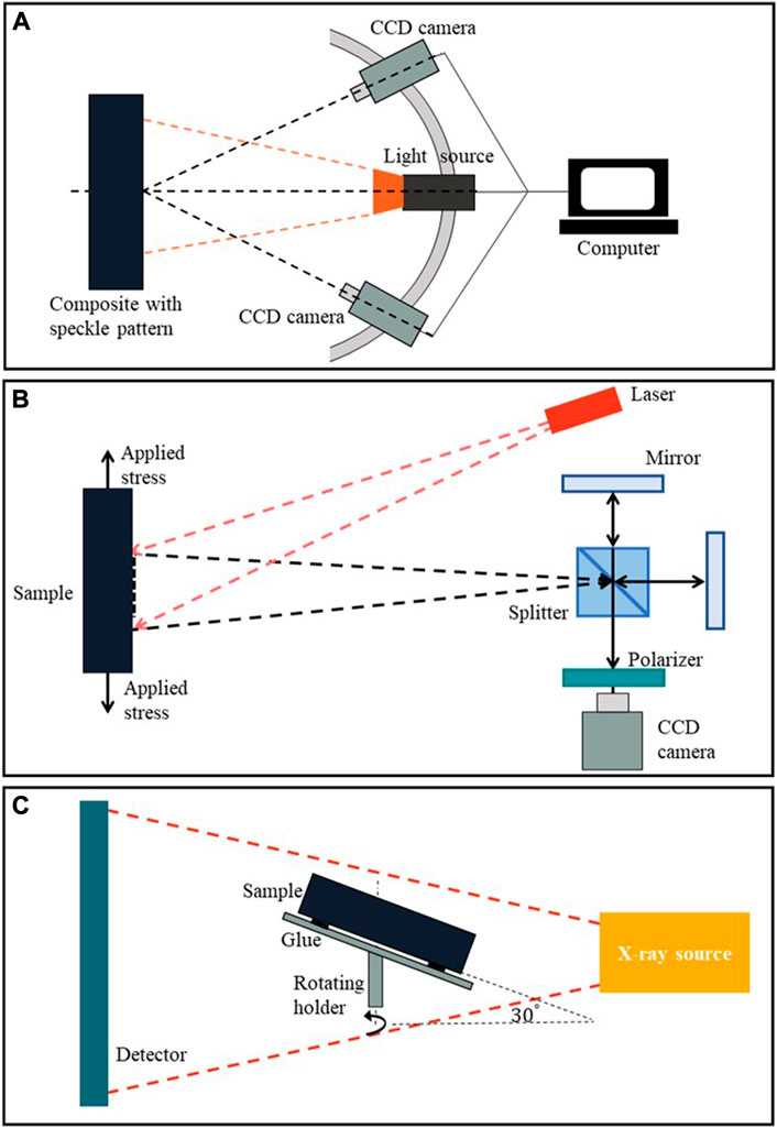
FIGURE 9. Schematic of system setups: (A) a typical DIC system setup for a composite sample with speckle pattern; (B) Schematic of a laser digital shearography setup; (C) an X-ray CT measurement setup.
DIC has been applied to explore composite defects/damage and SHM. DIC was proposed to monitor and measure full-field transient strain and deformation of the thermoplastic composite tow during manufacturing, which is a challenge of the AFP manufacturing process (Shadmehri and Hoa, 2019). Meanwhile, the ability to detect the gaps and overlaps between tows using the DIC system was evaluated by inspecting a flat panel consisting of a substrate layer and two tows. The results found that gaps and overlaps as small as about 0.4 mm could be detected. DIC has been proposed to evaluate the damage progression near the stress riser in graphite/PEEK and graphite/epoxy laminates employing strain maps obtained by DIC (Ambu et al., 2005). For DIC analysis, the camera resolution is about 4.2 Megapixels. The tested specimens were available in 2 mm and 2.2 mm thicknesses and had an 8 mm diameter center hole. Tensile loads of 0.1 and 25 kN were respectively applied to the samples to acquire the undeformed image and deformed image in the same area. By analyzing the images, the evaluation of displacement and strain field near the hole was obtained. Moreover, DIC was proven to be very useful for exploring the effects of damage developing near a stress concentration in composite laminates. A twill weave glass/polypropylene (G/PP) composite was tested in both the warp and weft directions through load-relaxation tensile tests for non-contact characterization of deformation and damage by surface DIC (Holmes et al., 2022). The results indicated that the surface DIC strain field was closely aligned with internal architecture such as the strain concentrations of fiber bundles near the surface. Also, a DIC system was used to measure the out-of-plane displacements and characteristics of the compression tests during the impact process which leads to BVID with about 1 mm depth in CFRP simples (Barile et al., 2019). The standardization of the DIC NDT&E technique is impossible to be available to each individual situation because of the flexibility and versatility of DIC systems (Pan, 2018).
In summary, DIC is a full-field and non-contact technique and has the potential for large-scale composite structure testing. A stochastic speckle pattern with random grey-level variations is essential to the accuracy of the measured displacements of the DIC (Janeliukstis and Chen, 2021), and the quality of speckle pattern can affect the results of testing and evaluation. Indeed, applying a random pattern using a marker or spray paint may influence the surface conditions of composite materials (Shadmehri and Hoa, 2019). It is also worth mentioning that when utilizing DIC to inspect large structures, the cost caused for applying speckle patterns is considerable.
3.3.2 Shearography
Shearography is a non-contact and full-field NDT&E technique based on laser interferometry and speckle patterns, which can provide full-field and quasi-real-time quantitative images of the surface displacements of a loaded composite structure (Hung, 2001). Shearography is a method to detect defects/damage in surface and subsurface with speckle patterns using interference of coherent light. The fringe pattern represents changes in the out-of-plane displacement derivative of the surface under test. As shown in Figure 9B, the coherent laser light scattered from the test surface passes through the shearing device, which splits the scene into two identical but displaced images before the image is focused on the detector. Each resolution element of the detector receives energy from two distinctly different locations on the surface being imaged (Dong and Ansari, 2011). The separation distance and direction between two positions on the object create the shear vector. When the object is stressed, shearography images will change. Surface contour deformation caused by defects such as debonding or delamination can be detected by comparing the original image with the loaded image. Shearography applied various stressing techniques to detect defects, including heating or cooling the test part, vacuum, pressure, mechanical bending, sound, ultrasonic signals, and microwaves (Beaumont et al., 2018).
As a qualitative approach, the shearographic methodology reveals the size and depth of delamination in FRPCs according to the measurement of dynamic response to the applied excitation of defects. De Angelis et al. (2012) utilized and evaluated the digital shearography method to detect delamination defects simulated by flat-bottom holes. The flat-bottom holes were located at different depths ranging from 1.7 to 3.2 mm and 1.5–4.0 mm with total thicknesses of CFRP specimens equal to 4 and 6 mm. The results demonstrated that shearography facilitated the assessment of artificial defects, with an error of less than 9% in size and depth. Subsequently, (Gryzagoridis et al., 2013), employed a digital shearography system to inspect the thermally excited sandwich composite cantilever beams for presenting and locating subsurface defects, such as voids or delamination. The use of digital shearography readily and vividly facilitated the location of induced defects. The digital shearography method has been used in detecting the subsurface defects of high-pressure composite tubes through subtraction between shearographic phase maps created at different pressure states (Xie and Zhou, 2018). Given that digital shearography is only a surface strain measurement method, defects are not detectable when the maximum out-of-plane deformation caused by loading is lower than the measurement sensitivity of digital shearography. In this study, all small defects (smaller than 0.5 mm) were not detected.
The shearography technique can be used to observe the variations of out-of-plane surface displacement due to damage development. To quantitatively discuss the ability of shearography to characterize in-situ subsurface damage, a comparison has been proposed between DIC and shearography (Zhang et al., 2022a). Open-hole tensile (OHT) test is imposed on anisotropic CFRP laminates to generate various defects. The thickness of tested CFRP is 2 mm with a hole diameter of 6 mm. With a series of different maximum loads, shearography images have revealed the linear nature of detected damage and the distribution of damage patterns. The damage patterns first appear close to the hole and free edges. However, DIC is unable to demonstrate the occurrence and growth of damage with images of strain field distribution.
Several other methods have been proposed to improve the accuracy and sensitivity of defect detection using shearography. Acoustic shearography is a new hybrid technique combining ultrasonic excitation with shearography imaging (Zhang et al., 2022b). Different from traditional shearography, acoustic shearography utilizes the stress loading generated from ultrasonic waves. The minimum defects detected by acoustic shearography is about 0.8 mm after conducting open-hole compression (OHC) tests of different maximum loads in CFRP specimens. Additionally, an image thresholding method based on self-organizing maps (SOMs) has demonstrated the ability to segment the shearography images of low-energy impact damages in CFRP samples (Schwedersky et al., 2022). Revel et al. (2017) utilized a Wavelet Transform algorithm to estimate the delamination size by shearography inspection quantitatively. A damaged sandwich panel with a 24 mm honeycomb core and a 1.5 mm depth-fiberglass skin was tested as the sample. The sample is characterized by a series of known circular defects having a diameter of 24 ± 0.05 mm. The algorithm successfully assessed the size of the defect with a result of 24.3 ± 0.05 mm and demonstrated to have better robustness compared with entropy based-threshold algorithm. The entropy based-threshold caused an underestimation in the evaluation of the defect size as it provides several disjointed objects in the image.
In summary, shearography has the capability of measuring out-of-plane displacement gradients in the sub-micrometer range (Revel et al., 2017), and successfully detecting defects (delamination, debonding, impact damage) in FRPCs (Hung et al., 2013) without compromising the investigated structure. Due to several uncertain sources and the difficulty of managing the output images, shearography usually remains a qualitative technique. In fact, with the continuous development of research, there are now also many methods proposed to reduce uncertainty for quantitative assessment of defects. In general, shearography is an NDT&E technique with great potential, particularly for SHM of FRPCs.
3.3.3 X-ray computed tomography
X-ray CT is a unique testing technique based on radiographic penetrating imaging that provides unrivaled information about the internal porosity, pores shape, dimension, and volume distribution without sample destruction (Landis and Keane, 2010; Hanhan et al., 2019). In general, X-ray CT imaging process is divided into two main steps: firstly, acquiring a series of 2D radiographs at many different angles of illumination; then creating a stack of cross-sectional slices from these 2D projections (radiographs) of the sample using a computed reconstruction algorithm and the information of internal structure can be obtained from the digital 3D greyscale representation (Withers et al., 2021). In addition, the image contrast of 2D radiographs relies on differences in the attenuation or phase of X-rays paths through the sample (Garcea et al., 2018). The obtained 3D representation can be quantitatively analyzed and virtually sliced in any direction. Moreover, areas of interest can be digitally color-coded, or rendered transparent in the form of 3D visualization. Figure 9C illustrates the schematic of an X-ray CT measurement setup.
X-ray radiography is a two-dimensional (2D) image technique representing the X-ray photons that passed through the sample mainly in the form of attenuation contrast (AC), differential phase contrast (DPC), and dark-field contrast (DFC). Tested materials attenuate or reduce the penetrating radiation through interaction processes involving scattering or absorption. The differences produced by differential absorption of penetrating radiation between defective and non-defective areas in samples will be recorded on the image. Moreover, the phase object placed in the X-ray beam path causes slight refraction of the beam transmitted through the object. The fundamental idea of DPC imaging depends on locally detecting these angular deviations (Pfeiffer et al., 2006). Furthermore, as the X-ray passes through the object, small angle scattering is generated by internal density fluctuations on the micron and sub-micron scale, e.g., at interfaces between material and air (Pfeiffer et al., 2008). Dark-field contrast (DFC) images reflects the total amount of radiation scattered at small angles by microscopic inhomogeneities like microcrack (Senck et al., 2018) or porosity (Revol et al., 2011) in FRPCs. Importantly, DFC images reveal information undisclosed by both AC and DPC imaging since DFC delivers morphological information in the sub-pixel regime depending on the local scattering power (Gusenbauer et al., 2016).
Owing to its high precision and sensitivity, X-ray CT is frequently used in the quantitative nondestructive evaluation of defects/damage in CFRP. Vasudevan et al. (2018) made detailed observations on the onset and growth of LVI damage in different angle plies of woven GFRP and Kevlar-FRP through X-ray CT scan imaging. The damaged area was measured and imaged through X-ray CT for each layer as shown in Figure 10. The image results illustrated that the bottommost layers were subjected to higher impact damage than the topmost layers and the outer Kevlar layers delayed delamination propagation internally. The extension of drilling-induced delamination in woven CFRP laminates has been quantitatively evaluated by X-ray CT scanning (Vaziri Sereshk and Bidhendi, 2016). The samples are produced by the hand layup technique with an orientation of
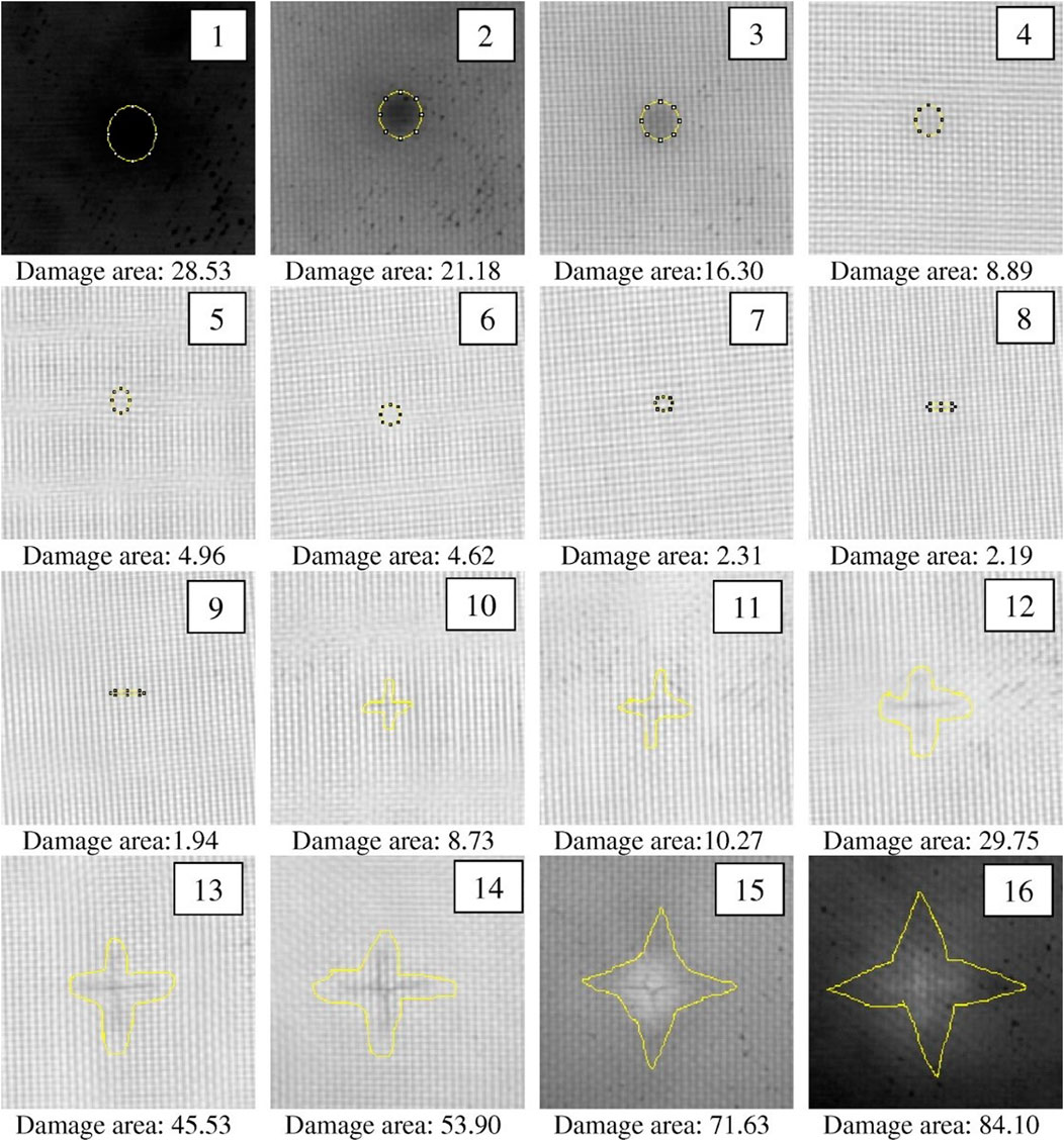
FIGURE 10. Ply-wise damage patterns in 16 layers (
X-ray and X-ray CT are also used to complement other NDT&E techniques to obtain more specific and quantitative defects/damage information. Differential phase and dark-field X-ray images have been used for investigating delamination and characterizing impact-induced damage extending along different fiber directions in a CFRP specimen with a size of 990 mm × 110 mm × 2 mm (Endrizzi et al., 2015). The full extent of delamination was observed with ultrasonic C-scan while damage extending along the fibers is well detectable in the phase-contrast X-ray images. Therefore, the complementarity of X-ray and ultrasonic C-scan in terms of imaging characteristics and scale facilitates the prediction of delamination expansion and size during impact. Also, we (Senck et al., 2018) qualitatively and quantitatively characterize microcracks in the (sub-) micrometer range in CFRP samples using a combination of X-ray CT, X-ray CT based on Talbot-Lau grating interferometry (TLGI-XCT), and radiography based on Talbot-Lau grating interferometry (XLGI-RT). Crack-like defects were introduced in CFRP samples with impact energy under laboratory conditions. The 2D and 3D visualization and quantification of damage at voxel sizes of 12.5, 22.8, and 50 µm have demonstrated the combination of TLGI-XCT and XLGI-RT can provide complementary images, including attenuation contrast (AC), differential phase contrast, and dark-field contrast (DFC).
In summary, X-ray CT has a huge advantage in providing visualization and quantitative analysis of internal features and details that are difficult/impossible to access externally. X-ray CT is being used increasingly in manufacturing composite materials and structures, not only to inspect defects/damage of products but also to provide feedback to optimize design and manufacturing quality. With good development prospects, the field of X-ray CT is expanding rapidly, including the range of applications for different types and structures of composite materials and the development of new imaging modalities (Withers et al., 2021). However, due to its disadvantages of complex equipment and harmful radiation, the maximum sample size is limited and usually the inspection can only be performed in the lab, which limit the application of X-ray CT to some degree.
4 Conclusion and future trends
Given the wide application of FRPCs in the industry and the existence of various defects/damage, a review on the detection, characterization, and evaluation of composite materials through NDT&E technologies was provided. The eight established methods: AE, UT, ECT, IRT, THz, DIC, shearography, and X-ray CT were evaluated independently and comprehensively concerning their performance in targeting major defects/damage. Results from recently published literature on advances in NDT&E of FRPCs were used. Each method has its own merits in certain aspects, but practically none of them can achieve the comprehensive detection of all possible defects or damage. Table 3 presents the benefits and limitations of the reviewed NDT&E technologies. Finding a method that fits perfectly can be challenging, but the information provided by the NDT&E methods is essential to ensuring the structural integrity of FRPCs.
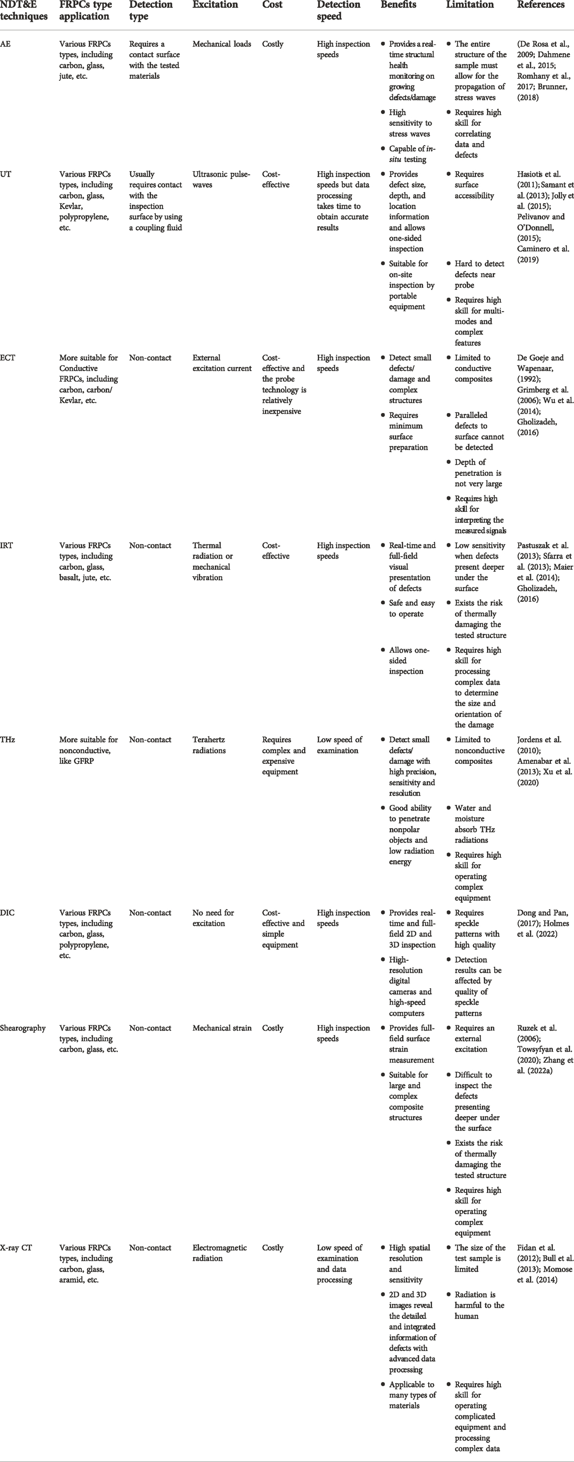
TABLE 3. Summary of the characteristics of established NDT&E techniques reviewed in this article.
Developments in NDT&E technologies are focused on accuracy, cost-effectiveness, real-time and full-field. Some NDT&E technologies have been proven effective in the detection and evaluation of defects and damage in composite materials. However, none of them can examine all possible structural detects in FRPCs. Recent studies have demonstrated that improving available technologies by combining different NDT&E techniques and fusion data is a potential approach for complex composite structures. For example, a combined NDT&E method consisting of IRT (for initial scanning and detection of near-surface defects) and UT (for a more detailed analysis of products that pass the first testing procedure) can improve detection accuracy (Katunin et al., 2021). UT and X-ray CT results can be used in evaluating impact damage in composite structures (Katunin et al., 2020). The final detection result depends not only on the size and nature of a defect but also on the resolution of NDT&E technologies. The resolution of most of the NDT&E technologies has not been established in the literature. The resolution is often dependent on the actual conditions of test environments and objects to be inspected, including NDT&E instrument properties, damage location, the accessibility of structures, and types of materials to be tested. All of these need to be considered influential factors for estimating the structural health of composite materials.
Moreover, the development of data processing algorithms is equally important to reduce estimation errors. For each technology, a general data algorithm process should be specified to improve evaluation speed and reduce errors in estimates. Given the complex defect mechanisms and detection methods, machine learning and deep learning have been increasingly applied to data processing algorithms to provide significant potential for NDT&E of FRPCs. Many NDT&E technologies have applied intelligent algorithms for the automatic detection and identification of defects through artificial neural networks. For instance, convolutional neural networks have been used to automatically extract features from raw data, classify ultrasonic signals (Shi et al., 2022), and train deep learning object detectors from the sequences of ultrasonic B-scans (Medak et al., 2021). In general, the algorithm enhancements can yield better detection accuracy or faster detection speed than previous analysis approaches. The increase in accuracy may require a larger amount of data acquisition and calculation, which will reduce the speed of detection. For increased speed of detection, some expensive powerful computing equipment may be required at present, which will increase the cost. However, as computing power continues to increase at essentially constant cost, these issues will soon be solved.
Currently, few studies have focused on the application of NDT&E to detect inhomogeneities in thick composites (Shafi et al., 2017; Djabali et al., 2018; Ibrahim et al., 2021) and hybrid reinforced composites, such as metal-fiber reinforced composites (Asta et al., 2015; Jakubczak and Bienias, 2019; Jasiuniene et al., 2019; Hu et al., 2021), due to complex structure, failure mechanism, and detection principle. Thick composites and hybrid reinforced composites are gradually becoming an integral part of many industries including marine, petrochemical, new energy, etc. Owing to extensive developments in composite applications, the inspection of hybrid reinforced composites and thick composites will be the focus of our future studies. Furthermore, natural fiber polymer composites have obtained increasing interest due to its renewability, low cost, and low abrasiveness.
Author contributions
JC: manuscript revise, project supervision, and final approval. ZY: literature search and manuscript writing. HJ: manuscript editing and project supervision.
Funding
This work was supported by the National Natural Science Foundation of China (Grants Nos. 52275549 and 52075486).
Conflict of interest
The authors declare that the research was conducted in the absence of any commercial or financial relationships that could be construed as a potential conflict of interest.
Publisher’s note
All claims expressed in this article are solely those of the authors and do not necessarily represent those of their affiliated organizations, or those of the publisher, the editors and the reviewers. Any product that may be evaluated in this article, or claim that may be made by its manufacturer, is not guaranteed or endorsed by the publisher.
References
Adams, D. O., and Hyer, M. W. (1994). Effects of layer waviness on the compression response of laminates, 1185. ASTM Special Technical Publication, 65. doi:10.1016/0142-1123(94)90450-2
Agrawal, S., Singh, K. K., and Sarkar, P. (2014). Impact damage on fibre-reinforced polymer matrix composite–a review. J. Compos. Mater. 48 (3), 317–332. doi:10.1177/0021998312472217
Ahmad, A. (1989). Metals handbook. Ninth Edition. United States: ASM International.Nondestructive evaluation and quality control
Al-Furjan, M., Shan, L., Shen, X., Zarei, M., Hajmohammad, M., and Kolahchi, R. (2022). A review on fabrication techniques and tensile properties of glass, carbon, and Kevlar fiber reinforced rolymer composites. J. Mater. Res. Technol. 19, 2930–2959. doi:10.1016/j.jmrt.2022.06.008
Alarifi, I. M., Movva, V., Rahimi-Gorji, M., and Asmatulu, R. (2019). Performance analysis of impact-damaged laminate composite structures for quality assurance. J. Braz. Soc. Mech. Sci. Eng. 41 (8), 27–34. doi:10.1007/s40430-019-1841-5
Altmann, A., Gesell, P., and Drechsler, K. (2015). Strength prediction of ply waviness in composite materials considering matrix dominated effects. Compos. Struct. 127, 51–59. doi:10.1016/j.compstruct.2015.02.024
Alves, M. P., Cimini Junior, C. A., and Ha, S. K. (2021). Fiber waviness and its effect on the mechanical performance of fiber reinforced polymer composites: An enhanced review. Compos. Part A Appl. Sci. Manuf. 149, 106526. doi:10.1016/j.compositesa.2021.106526
Alves, M. P., Gul, W., Cimini Junior, C. A., and Ha, S. K. (2022). A review on industrial perspectives and challenges on material, manufacturing, design and development of compressed hydrogen storage tanks for the transportation sector. Energies 15 (14), 5152. doi:10.3390/en15145152
Ambu, R., Aymerich, F., and Bertolino, F. (2005). Investigation of the effect of damage on the strength of notched composite laminates by digital image correlation. J. Strain Analysis Eng. Des. 40 (5), 451–461. doi:10.1243/030932405X16106
Amenabar, I., Lopez, F., and Mendikute, A. (2013). In introductory review to THz non-destructive testing of composite mater. J. Infrared Millim. Terahertz Waves 34 (2), 152–169. doi:10.1007/s10762-012-9949-z
Antin, K.-N., Machado, M. A., Santos, T. G., and Vilaça, P. (2019). Evaluation of different non-destructive testing methods to detect imperfections in unidirectional carbon fiber composite ropes. J. Nondestr. Eval. 38 (1), 23–12. doi:10.1007/s10921-019-0564-y
Arumugam, V., Sidharth, A. A. P., and Santulli, C. (2014). Failure modes characterization of impacted carbon fibre reinforced plastics laminates under compression loading using acoustic emission. J. Compos. Mater. 48 (28), 3457–3468. doi:10.1177/0021998313509504
Askaripour, K., and Zak, A. (2019). A survey of scrutinizing delaminated composites via various categories of sensing apparatus. J. Compos. Sci. 3 (4), 95. doi:10.3390/jcs3040095
Asokkumar, A., Jasiūnienė, E., Raišutis, R., and Kažys, R. J. (2021). Comparison of ultrasonic non-contact air-coupled techniques for characterization of impact-type defects in pultruded gfrp composites. Materials 14 (5), 1058. doi:10.3390/ma14051058
Asta, E., Cambiasso, F., Balderrama, J., and Rios, J. (2015). Determination of fracture toughness J on fiber-metal laminate type CARALL with sheets of aluminium 6061. Procedia Mater. Sci. 25, 530–537. doi:10.1016/j.mspro.2015.05.026
Awerbuch, J. (1997). On the identification of failure mechanisms in composite laminates through acoustic emission. NDT E Int. 2 (30), 218–258. doi:10.1016/0963-8695(94)90552-5
Bahonar, M., and Safizadeh, M. S. (2022). Investigation of real delamination detection in composite structure using air-coupled ultrasonic testing. Compos. Struct. 280, 114939. doi:10.1016/j.compstruct.2021.114939
Balageas, D. L. (2012). Defense and illustration of time-resolved pulsed thermography for NDE. Quantitative InfraRed Thermogr. J. 9 (1), 3–32. doi:10.1080/17686733.2012.676902
Bang, H.-T., Park, S., and Jeon, H. (2020). Defect identification in composite materials via thermography and deep learning techniques. Compos. Struct. 246, 112405. doi:10.1016/j.compstruct.2020.112405
Bao, G., Fan, B., and Evans, A. (1992). Mixed mode delamination cracking in brittle matrix composites. Mech. Mater. 13 (1), 59–66. doi:10.1016/0167-6636(92)90036-D
Barile, C., Casavola, C., and Pappalettera, G. (2019). Digital image correlation comparison of damaged and undamaged aeronautical CFRPs during compression tests. Materials 12 (2), 249. doi:10.3390/ma12020249
Barile, C., Casavola, C., Pappalettera, G., and Kannan, V. P. (2020). Application of different acoustic emission descriptors in damage assessment of fiber reinforced plastics: A comprehensive review. Eng. Fract. Mech. 235, 107083. doi:10.1016/j.engfracmech.2020.107083
Beaumont, P. W., Zweben, C. H., Gdutos, E., Talreja, R., Poursartip, A., Clyne, T. W., et al. (2018). Comprehensive composite materials II. Amsterdam, Netherlands: Elsevier.
Belnoue, J. P. H., Nixon-Pearson, O. J., Thompson, A. J., Ivanov, D. S., Potter, K. D., and Hallett, S. R. (2018). Consolidation-driven defect generation in thick composite parts. J. Manuf. Sci. Eng. 140 (7), 071006. doi:10.1115/1.4039555
Bergant, Z., Janez, J., and Grum, J. (2017). “Ultrasonic C-scan testing of epoxy/glass fiber composite,” in The 14th international conference of the slovenian society for non-destructive testing (Bernardin, Slovenia, 41–48.
Besson, A., and Minasyan, A. (2017). “Terahertz imaging for composite non-destructive testing,” in 15th asia pacific conference for non-destructive testing (Singapore, 28–30.
Boccardi, S., Boffa, N. D., Carlomagno, G. M., Del Core, G., Meola, C., Monaco, E., et al. (2019). Lock-in thermography and ultrasonic testing of impacted basalt fibers reinforced thermoplastic matrix composites. Appl. Sci. 9 (15), 3025. doi:10.3390/app9153025
Boccardi, S., Carlomagno, G., Meola, C., Russo, P., and Simeoli, G. (2014). “Infrared thermography to evaluate impact damaging of thermoplastic composites,” in QIRT conference 2014 (Bordeaux, France.
Bolotin, V. V. (1996). Delaminations in composite structures: Its origin, buckling, growth and stability. Compos. Part B Eng. 27 (2), 129–145. doi:10.1016/1359-8368(95)00035-6
Bosch, C., Briottet, L., Couvant, T., Frégonèse, M., and Oudriss, A. (2019). “Mechanical tests in corrosive environments and under gaseous hydrogen,” in Mechanics-microstructure-corrosion coupling (Amsterdam, Netherlands: Elsevier), 481–505.
Broughton, W. (2012). “Testing the mechanical, thermal and chemical properties of adhesives for marine environments,” in Adhesives in marine engineering (Amsterdam, Netherlands: Elsevier), 99–154.
Brunner, A. J. (2018). Identification of damage mechanisms in fiber-reinforced polymer-matrix composites with Acoustic Emission and the challenge of assessing structural integrity and service-life. Constr. Build. Mater. 173, 629–637. doi:10.1016/j.conbuildmat.2018.04.084
Bull, D., Spearing, S., Sinclair, I., and Helfen, L. (2013). Three-dimensional assessment of low velocity impact damage in particle toughened composite laminates using micro-focus X-ray computed tomography and synchrotron radiation laminography. Compos. Part A Appl. Sci. Manuf. 52, 62–69. doi:10.1016/j.compositesa.2013.05.003
Caminero, M., García-Moreno, I., Rodriguez, G., and Chacon, J. (2019). Internal damage evaluation of composite structures using phased array ultrasonic technique: Impact damage assessment in CFRP and 3D printed reinforced composites. Compos. Part B Eng. 165, 131–142. doi:10.1016/j.compositesb.2018.11.091
Cao, H., Ma, M., Jiang, M., Sun, L., Zhang, L., Jia, L., et al. (2020). Experimental investigation of impactor diameter effect on low-velocity impact response of CFRP laminates in a drop-weight impact event. Materials 13 (18), 4131. doi:10.3390/ma13184131
Chen, J., Wang, X., Yang, X., Zhang, L., and Wu, H. (2021). Application of air-coupled ultrasonic nondestructive testing in the measurement of elastic modulus of materials. Appl. Sci. 11 (19), 9240. doi:10.3390/app11199240
Cheng, J., Qiu, J., Xu, X., Ji, H., Takagi, T., and Uchimoto, T. (2016). Research advances in eddy current testing for maintenance of carbon fiber reinforced plastic composites. Int. J. Appl. Electromagn. Mech. 51 (3), 261–284. doi:10.3233/JAE-150168
Cheng, L., and Tian, G. Y. (2012). Comparison of nondestructive testing methods on detection of delaminations in composites. J. sensors 2012, 1–7. doi:10.1155/2012/408437
Cheng, L., and Tian, G. Y. (2011). Surface crack detection for carbon fiber reinforced plastic (CFRP) materials using pulsed eddy current thermography. IEEE Sens. J. 11 (12), 3261–3268. doi:10.1109/JSEN.2011.2157492
Chulkov, A., Gaverina, L., Pradere, C., Batsale, J.-C., and Vavilov, V. (2015). Water detection in honeycomb composite structures using terahertz thermography. Russ. J. Nondestruct. Test. 51 (8), 520–523. doi:10.1134/S1061830915080033
Cinar, K., and Ersoy, N. (2015). Effect of fibre wrinkling to the spring-in behaviour of L-shaped composite materials. Compos. Part A Appl. Sci. Manuf. 69, 105–114. doi:10.1016/j.compositesa.2014.10.025
Cui, H., Li, B., Zhou, L. B., and Liu, W. (2022). Damage detection in thick plate structures based on ultrasonic SH wave. Smart Mat. Struct. 31 (9), 095018. doi:10.1088/1361-665X/ac8030
Dahmene, F., Yaacoubi, S., and Mountassir, M. E. (2015). Acoustic emission of composites structures: Story, success, and challenges. Phys. Procedia 70, 599–603. doi:10.1016/j.phpro.2015.08.031
Davies, G. A., and Zhang, X. (1995). Impact damage prediction in carbon composite structures. Int. J. Impact Eng. 16 (1), 149–170. doi:10.1016/0734-743X(94)00039-Y
Dayal, V., Benedict, Z. G., Bhatnagar, N., and Harper, A. G. (2018). “Development of composite calibration standard for quantitative NDE by ultrasound and thermography,” in AIP conference proceedings (Published Online: AIP Publishing LLC), 060006.
De Angelis, G., Meo, M., Almond, D. P., Pickering, S. G., and Angioni, S. L. (2012). A new technique to detect defect size and depth in composite structures using digital shearography and unconstrained optimization. NDT E Int. 45 (1), 91–96. doi:10.1016/j.ndteint.2011.07.007
De Goeje, M., and Wapenaar, K. (1992). Non-destructive inspection of carbon fibre-reinforced plastics using eddy current methods. Composites 23 (3), 147–157. doi:10.1016/0010-4361(92)90435-W
De Rosa, I. M., Santulli, C., Sarasini, F., and Valente, M. (2009). Post-impact damage characterization of hybrid configurations of jute/glass polyester laminates using acoustic emission and IR thermography. Compos. Sci. Technol. 69 (7-8), 1142–1150. doi:10.1016/j.compscitech.2009.02.011
Destic, F., and Bouvet, C. (2016). Impact damages detection on composite materials by THz imaging. Case Stud. Nondestruct. Test. Eval. 6, 53–62. doi:10.1016/j.csndt.2016.09.003
Destic, F., Petitjean, Y., Massenot, S., Mollier, J.-C., and Barbieri, S. (2010). “THz qcl—based active imaging applied to composite materials diagnostic,” in 35th international conference on infrared, millimeter, and terahertz waves (Rome, Italy: IEEE), 1–2.
Djabali, A., Toubal, L., Zitoune, R., and Rechak, S. (2018). An experimental investigation of the mechanical behavior and damage of thick laminated carbon/epoxy composite. Compos. Struct. 184, 178–190. doi:10.1016/j.compstruct.2017.09.069
Dodwell, T., Butler, R., and Hunt, G. (2014). Out-of-plane ply wrinkling defects during consolidation over an external radius. Compos. Sci. Technol. 105, 151–159. doi:10.1016/j.compscitech.2014.10.007
Dong, C. (2018). Review of natural fibre-reinforced hybrid composites. J. Reinf. Plastics Compos. 37 (5), 331–348. doi:10.1177/0731684417745368
Dong, J., Locquet, A., and Citrin, D. (2016a). Enhanced terahertz imaging of small forced delamination in woven glass fibre-reinforced composites with wavelet de-noising. J. Infrared Millim. Terahertz Waves 37 (3), 289–301. doi:10.1007/s10762-015-0226-9
Dong, J., Locquet, A., Declercq, N. F., and Citrin, D. (2016b). Polarization-resolved terahertz imaging of intra-and inter-laminar damages in hybrid fiber-reinforced composite laminate subject to low-velocity impact. Compos. Part B Eng. 92, 167–174. doi:10.1016/j.compositesb.2016.02.016
Dong, J., Pomarède, P., Chehami, L., Locquet, A., Meraghni, F., Declercq, N. F., et al. (2018). Visualization of subsurface damage in woven carbon fiber-reinforced composites using polarization-sensitive terahertz imaging. NDT E Int. 99, 72–79. doi:10.1016/j.ndteint.2018.07.001
Dong, Y., and Ansari, F. (2011). “Non-destructive testing and evaluation (NDT/NDE) of civil structures rehabilitated using fiber reinforced polymer (FRP) composites,” in Service life estimation and extension of civil engineering structures (Amsterdam, Netherlands: Elsevier), 193–222.
Dong, Y., and Pan, B. (2017). A review of speckle pattern fabrication and assessment for digital image correlation. Exp. Mech. 57 (8), 1161–1181. doi:10.1007/s11340-017-0283-1
Duan, Y., Zhang, H., Maldague, X. P., Ibarra-Castanedo, C., Servais, P., Genest, M., et al. (2019). Reliability assessment of pulsed thermography and ultrasonic testing for impact damage of CFRP panels. NDT E Int. 102, 77–83. doi:10.1016/j.ndteint.2018.11.010
Dubois, M., and Drake, T. E. (2011). Evolution of industrial laser-ultrasonic systems for the inspection of composites. Nondestruct. Test. Eval. 26 (3-4), 213–228. doi:10.1080/10589759.2011.573552
Duchene, P., Chaki, S., Ayadi, A., and Krawczak, P. (2018). A review of non-destructive techniques used for mechanical damage assessment in polymer composites. J. Mat. Sci. 53 (11), 7915–7938. doi:10.1007/s10853-018-2045-6
Ellison, A., and Kim, H. (2020). Shadowed delamination area estimation in ultrasonic C-scans of impacted composites validated by X-ray CT. J. Compos. Mater. 54 (4), 549–561. doi:10.1177/0021998319865311
Endrizzi, M., Murat, B., Fromme, P., and Olivo, A. (2015). Edge-illumination X-ray dark-field imaging for visualising defects in composite structures. Compos. Struct. 134, 895–899. doi:10.1016/j.compstruct.2015.08.072
Farnand, K., Zobeiry, N., Poursartip, A., and Fernlund, G. (2017). Micro-level mechanisms of fiber waviness and wrinkling during hot drape forming of unidirectional prepreg composites. Compos. Part A Appl. Sci. Manuf. 103, 168–177. doi:10.1016/j.compositesa.2017.10.008
Favro, L., Thomas, R., Han, X., Ouyang, Z., Newaz, G., and Gentile, D. (2001). Sonic infrared imaging of fatigue cracks. Int. J. fatigue 23, 471–476. doi:10.1016/S0142-1123(01)00151-7
Fawcett, A. J., and Oakes, G. D. (2006). “Boeing composite airframe damage tolerance and service experience,” in Composite damage tolerance & maintenance workshop.
Fidan, S., Sınmazçelik, T., and Avcu, E. (2012). Internal damage investigation of the impacted glass/glass+ aramid fiber reinforced composites by micro-computerized tomography. NDT E Int. 51, 1–7. doi:10.1016/j.ndteint.2012.07.005
Fromme, P., Endrizzi, M., and Olivo, A. (2018). “Defect imaging in composite structures,” in AIP conference proceedings (Published Online: AIP Publishing LLC).
Fualdes, C., and Morteau, E. (2006). “Composites@ Airbus damage tolerance methodology,” in FAA workshop for composite damage tolerance and maintenance (Chicago IL.
Gao, H., Ali, S., and Lopez, B. (2010). Efficient detection of delamination in multilayered structures using ultrasonic guided wave EMATs. NDT E Int. 43 (4), 316–322. doi:10.1016/j.ndteint.2010.03.004
Gao, T., Wang, Y., and Qing, X. (2021). A new laser ultrasonic inspection method for the detection of multiple delamination defects. Materials 14 (9), 2424. doi:10.3390/ma14092424
Garcea, S., Wang, Y., and Withers, P. (2018). X-ray computed tomography of polymer composites. Compos. Sci. Technol. 156, 305–319. doi:10.1016/j.compscitech.2017.10.023
Garnier, C., Pastor, M.-L., Eyma, F., and Lorrain, B. (2011). The detection of aeronautical defects in situ on composite structures using Non Destructive Testing. Compos. Struct. 93 (5), 1328–1336. doi:10.1016/j.compstruct.2010.10.017
Gaudenzi, P., Bernabei, M., Dati, E., De Angelis, G., Marrone, M., and Lampani, L. (2014). On the evaluation of impact damage on composite materials by comparing different NDI techniques. Compos. Struct. 118, 257–266. doi:10.1016/j.compstruct.2014.07.048
Gay, D., and Hoa, S. V. (2007). Composite materials: Design and applications. Florida, USA: CRC Press.
George, J., Sreekala, M., and Thomas, S. (2001). A review on interface modification and characterization of natural fiber reinforced plastic composites. Polym. Eng. Sci. 41 (9), 1471–1485. doi:10.1002/pen.10846
Ghadermazi, K., Khozeimeh, M., Taheri-Behrooz, F., and Safizadeh, M. (2015). Delamination detection in glass–epoxy composites using step-phase thermography (SPT). Infrared Phys. Technol. 72, 204–209. doi:10.1016/j.infrared.2015.08.006
Gholizadeh, S. (2016). A review of non-destructive testing methods of composite materials. Procedia Struct. Integr. 1, 50–57. doi:10.1016/j.prostr.2016.02.008
Greenhalgh, E. (2009). Failure analysis and fractography of polymer composites. Amsterdam, Netherlands: Elsevier.
Gresil, M., and Giurgiutiu, V. (2015). Prediction of attenuated guided waves propagation in carbon fiber composites using Rayleigh damping model. J. Intelligent Material Syst. Struct. 26 (16), 2151–2169. doi:10.1177/1045389X14549870
Grimberg, R., Savin, A., Steigmann, R., and Bruma, A. (2006). Eddy current examination of carbon fibres in carbon-epoxy composites and Kevlar. Int. J. Mater. Prod. Technol. 27 (3), 221–228. doi:10.1504/IJMPT.2006.011272
Gryzagoridis, J., Oliver, G., and Findeis, D. (2013). Modal frequency versus shearography in detecting and locating voids/delaminations in sandwich composites. insight 55 (5), 249–252. doi:10.1784/insi.2012.55.5.249
Guo, Y., Li, D., Chen, Y., Li, J., Yang, Y., and Fang, F. (2013). Application progress of AE in fiber reinforced polymer matrix composites. J. Eng. Plastics Appl. 41 (4), 107–110.
Gupta, M., and Srivastava, R. (2016). Mechanical properties of hybrid fibers-reinforced polymer composite: A review. Polymer-Plastics Technol. Eng. 55 (6), 626–642. doi:10.1080/03602559.2015.1098694
Gupta, R., Mitchell, D., Blanche, J., Harper, S., Tang, W., Pancholi, K., et al. (2021). A review of sensing technologies for non-destructive evaluation of structural composite materials. J. Compos. Sci. 5 (12), 319. doi:10.3390/jcs5120319
Gusenbauer, C., Leiss-Holzinger, E., Senck, S., Mathmann, K., Kastner, J., Hunger, S., et al. (2016). Characterization of medical and biological samples with a Talbot–Lau grating interferometer μXCT in comparison to reference methods. Case Stud. Nondestruct. Test. Eval. 6, 30–38. doi:10.1016/j.csndt.2016.02.001
Hamam, Z., Godin, N., Fusco, C., Doitrand, A., and Monnier, T. (2021). Acoustic emission signal due to fiber break and fiber matrix debonding in model composite: A computational study. Appl. Sci. 11 (18), 8406. doi:10.3390/app11188406
Hamstad, M. A. (1986). A review: Acoustic emission, a tool for composite-materials studies. Exp. Mech. 26 (1), 7–13. doi:10.1007/bf02319949
Han, B., Sharma, S., Nguyen, T. A., Li, L., and Bhat, K. S. (2020). Fiber-reinforced nanocomposites: Fundamentals and applications. Amsterdam, Netherlands: Elsevier.
Han, D.-H., and Kang, L.-H. (2018). Nondestructive evaluation of GFRP composite including multi-delamination using THz spectroscopy and imaging. Compos. Struct. 185, 161–175. doi:10.1016/j.compstruct.2017.11.012
Hanafee, Z., Khalina, A., Norkhairunnisa, M., Syams, Z. E., and Ern, L. K. (2019). The effect of different linear robot travel speed on mass flowrate of pineapple leaf fibre (PALF) automated spray up composite. Compos. Part B Eng. 156, 220–228. doi:10.1016/j.compositesb.2018.08.090
Hanhan, I., Agyei, R., Xiao, X., and Sangid, M. D. (2019). Comparing non-destructive 3D X-ray computed tomography with destructive optical microscopy for microstructural characterization of fiber reinforced composites. Compos. Sci. Technol. 184, 107843. doi:10.1016/j.compscitech.2019.107843
Hasiotis, T., Badogiannis, E., and Tsouvalis, N. G. (2011). Application of ultrasonic C-scan techniques for tracing defects in laminated composite materials. Strojniški vestnik-Journal Mech. Eng. 57 (3), 192–203. doi:10.5545/sv-jme.2010.170
He, Y., Tian, G., Pan, M., and Chen, D. (2014). Impact evaluation in carbon fiber reinforced plastic (CFRP) laminates using eddy current pulsed thermography. Compos. Struct. 109, 1–7. doi:10.1016/j.compstruct.2013.10.049
Heslehurst, R. B. (2014). Defects and damage in composite materials and structures. Florida, USA: CRC Press.
Hocheng, H., Puw, H., and Huang, Y. (1993). Preliminary study on milling of unidirectional carbon fibre-reinforced plastics. Compos. Manuf. 4 (2), 103–108. doi:10.1016/0956-7143(93)90077-L
Holmes, J., Sommacal, S., Stachurski, Z., Das, R., and Compston, P. (2022). Digital image and volume correlation with X-ray micro-computed tomography for deformation and damage characterisation of woven fibre-reinforced composites. Compos. Struct. 279, 114775. doi:10.1016/j.compstruct.2021.114775
Horrmann, S., Adumitroaie, A., and Schagerl, M. (2016a). The effect of ply folds as manufacturing defect on the fatigue life of CFRP materials. Frat. Ed. integrita Strutt. 10 (38), 76–81. doi:10.3221/IGF-ESIS.38.10
Horrmann, S., Adumitroaie, A., Viechtbauer, C., and Schagerl, M. (2016b). The effect of fiber waviness on the fatigue life of CFRP materials. Int. J. Fatigue 90, 139–147. doi:10.1016/j.ijfatigue.2016.04.029
Hsu, D. K., Lee, K.-S., Park, J.-W., Woo, Y.-D., and Im, K.-H. (2012). NDE inspection of terahertz waves in wind turbine composites. Int. J. Precis. Eng. Manuf. 13 (7), 1183–1189. doi:10.1007/s12541-012-0157-5
Hu, J., Zhang, H., Sfarra, S., Perilli, S., Sergi, C., Sarasini, F., et al. (2021). Multi-excitation infrared fusion for impact evaluation of aluminium-BFRP/GFRP hybrid composites. Sensors 21 (17), 5961. doi:10.3390/s21175961
Huang, H., and Talreja, R. (2005). Effects of void geometry on elastic properties of unidirectional fiber reinforced composites. Compos. Sci. Technol. 65 (13), 1964–1981. doi:10.1016/j.compscitech.2005.02.019
Hung, M. (2001). “Shearography and applications in nondestructive evaluation of structures,” in Proceedings of the international conference on FRP composites in civil engineering (Hong Kong, China: Elsevier), 1723–1730.
Hung, Y., Chen, Y. S., Ng, S., Liu, L., Huang, Y., Luk, B., et al. (2009). Review and comparison of shearography and active thermography for nondestructive evaluation. Mater. Sci. Eng. R Rep. 64 (5-6), 73–112. doi:10.1016/j.mser.2008.11.001
Hung, Y., Yang, L., and Huang, Y. (2013). “Non-destructive evaluation (NDE) of composites: Digital shearography,” in Non-destructive evaluation (NDE) of polymer matrix composites (Britain: Woodhead Publishing), 84–115.
Ibrahim, M., Headland, D., Withayachumnankul, W., and Wang, C. (2021). Nondestructive testing of defects in polymer–matrix composite materials for marine applications using terahertz waves. J. Nondestr. Eval. 40 (2), 37–11. doi:10.1007/s10921-021-00767-9
Irving, P. E., and Soutis, C. (2019). Polymer composites in the aerospace industry. 2nd edition. Britain: Woodhead Publishing.
Jakubczak, P., and Bienias, J. (2019). Non-destructive damage detection in fibre metal laminates. J. Nondestr. Eval. 38 (2), 49. doi:10.1007/s10921-019-0588-3
James, P., Gaddikeri, K., Varughese, B., and Rao, M. S. (2014). Realisation of shear flow at crucial spar splice joints of composite wing in idealised wing test box. Procedia Eng. 86, 718–726. doi:10.1016/j.proeng.2014.11.090
Janeliukstis, R., and Chen, X. (2021). Review of digital image correlation application to large-scale composite structure testing. Compos. Struct. 271, 114143. doi:10.1016/j.compstruct.2021.114143
Jariwala, H., and Jain, P. (2019). A review on mechanical behavior of natural fiber reinforced polymer composites and its applications. J. Reinf. Plastics Compos. 38 (10), 441–453. doi:10.1177/0731684419828524
Jasiuniene, E., Mazeika, L., Samaitis, V., Cicenas, V., and Mattsson, D. (2019). Ultrasonic non-destructive testing of complex titanium/carbon fibre composite joints. Ultrasonics 95, 13–21. doi:10.1016/j.ultras.2019.02.009
Jawaid, M., Thariq, M., and Saba, N. (2018). Durability and life prediction in biocomposites, fibre-reinforced composites and hybrid composites. Cambridge, United Kingdom: Woodhead Publishing.
Jeon, K. W., Shin, K. B., and Kim, J. S. (2011). A study on fatigue life and strength of a GFRP composite bogie frame for urban subway trains. Procedia Eng. 10, 2405–2410. doi:10.1016/j.proeng.2011.04.396
Jeong, H. (1997). Effects of voids on the mechanical strength and ultrasonic attenuation of laminated composites. J. Compos. Mater. 31 (3), 276–292. doi:10.1177/002199839703100303
Jiang, J., and Wang, C. (2019). Modelling and backstepping motion control of the aircraft skin inspection robot. Comput. Model. Eng. Sci. 120 (1), 105–121. doi:10.32604/cmes.2019.06277
Johnson, S. (2014). Thermoelastic stress analysis for detecting and characterizing static damage initiation in composite lap shear joints. Compos. Part B Eng. 56, 740–748. doi:10.1016/j.compositesb.2013.09.014
Jolly, M. R., Prabhakar, A., Sturzu, B., Hollstein, K., Singh, R., Thomas, S., et al. (2015). Review of non-destructive testing (NDT) techniques and their applicability to thick walled composites. Procedia CIRP 38, 129–136. doi:10.1016/j.procir.2015.07.043
Jordens, C., Scheller, M., Wietzke, S., Romeike, D., Jansen, C., Zentgraf, T., et al. (2010). Terahertz spectroscopy to study the orientation of glass fibres in reinforced plastics. Compos. Sci. Technol. 70 (3), 472–477. doi:10.1016/j.compscitech.2009.11.022
Juarez, P., and Leckey, C. A. (2018). “Aerogel to simulate delamination and porosity defects in carbon-fiber reinforced polymer composites,” in AIP conference proceedings (Published Online: AIP Publishing LLC).
Jung, D., Yu, W.-R., Ahn, H., and Na, W. (2022). New b-value parameter for quantitatively monitoring the structural health of carbon fiber-reinforced composites. Mech. Syst. Signal Process. 165, 108328. doi:10.1016/j.ymssp.2021.108328
Junyan, L., Yang, L., Fei, W., and Yang, W. (2015). Study on probability of detection (POD) determination using lock-in thermography for nondestructive inspection (NDI) of CFRP composite materials. Infrared Phys. Technol. 71, 448–456. doi:10.1016/j.infrared.2015.06.007
Kaiser, J. (1950). An investigation into the occurrence of noises in tensile tests, or a study of acoustic phenomena in tensile tests. Unpublished Doctoral Thesis. Munich: Tech. Hosch.
Kalyanavalli, V., Ramadhas, T. A., and Sastikumar, D. (2018). Long pulse thermography investigations of basalt fiber reinforced composite. NDT E Int. 100, 84–91. doi:10.1016/j.ndteint.2018.08.007
Karabutov, A., and Podymova, N. (2014). Quantitative analysis of the influence of voids and delaminations on acoustic attenuation in CFRP composites by the laser-ultrasonic spectroscopy method. Compos. Part B Eng. 56, 238–244. doi:10.1016/j.compositesb.2013.08.040
Karbhari, V. M. (2013). “Non-destructive evaluation (NDE) of composites: Detecting delamination defects using mechanical impedance, ultrasonic and infrared thermographic techniques,” in Non-destructive evaluation (NDE) of polymer matrix composites (British: Woodhead Publishing), 279–305.
Karpowicz, N., Zhong, H., Zhang, C., Lin, K.-I., Hwang, J.-S., Xu, J., et al. (2005). Compact continuous-wave subterahertz system for inspection applications. Appl. Phys. Lett. 86 (5), 054105. doi:10.1063/1.1856701
Katunin, A., Dragan, K., Nowak, T., and Chalimoniuk, M. (2021). Quality control approach for the detection of internal lower density areas in composite disks in industrial conditions based on a combination of NDT techniques. Sensors 21 (21), 7174. doi:10.3390/s21217174
Katunin, A., Wronkowicz-Katunin, A., and Dragan, K. (2020). Impact damage evaluation in composite structures based on fusion of results of ultrasonic testing and X-ray computed tomography. Sensors 20 (7), 1867. doi:10.3390/s20071867
Katunin, A., Wronkowicz-Katunin, A., and Wachla, D. (2019). Impact damage assessment in polymer matrix composites using self-heating based vibrothermography. Compos. Struct. 214, 214–226. doi:10.1016/j.compstruct.2019.02.003
Ke, W., Castaings, M., and Bacon, C. (2009). 3D finite element simulations of an air-coupled ultrasonic NDT system. NDT E Int. 42 (6), 524–533. doi:10.1016/j.ndteint.2009.03.002
Kersemans, M., Verboven, E., Segers, J., Hedayatrasa, S., and Paepegem, W. V. (2018). Non-destructive testing of composites by ultrasound, local defect resonance and thermography. Multidiscip. Digit. Publ. Inst. Proc. 2 (8), 554. doi:10.3390/ICEM18-05464
Khan, B., Potter, K. D., and Wisnom, M. R. (2006). “Simulation of process induced defects in resin transfer moulded woven carbon fibre laminates and their effect on mechanical behaviour,” in The 8th international conference on flow processes in composite materials (FPCM8) (Douai, France: Ecole des Mines de Douai), Douai, France. 261–270.
Kim, H.-J. (1997). Postbuckling analysis of composite laminates with a delamination. Comput. Struct. 62 (6), 975–983. doi:10.1016/S0045-7949(96)00290-8
Kim, H., and Kwon, H. (2004). Buckling of composite flanges in partially disbonded adhesive joints. J. Compos. Mater. 38 (24), 2213–2230. doi:10.1177/0021998304045592
Koyama, K., Hoshikawa, H., and Kojima, G. (2013). Eddy current nondestructive testing for carbon fiber-reinforced composites. J. Press. Vessel Technol. 135 (4). doi:10.1115/1.4023253
Kratz, J., Hsiao, K., Fernlund, G., and Hubert, P. (2013). Thermal models for MTM45-1 and Cycom 5320 out-of-autoclave prepreg resins. J. Compos. Mater. 47 (3), 341–352. doi:10.1177/0021998312440131
Kulkarni, P., Mali, K. D., and Singh, S. (2020). An overview of the formation of fibre waviness and its effect on the mechanical performance of fibre reinforced polymer composites. Compos. Part A Appl. Sci. Manuf. 137, 106013. doi:10.1016/j.compositesa.2020.106013
Kumekawa, N., Mori, Y., Tanaka, H., and Matsuzaki, R. (2022). Experimental evaluation of variable thickness 3D printing of continuous carbon fiber-reinforced composites. Compos. Struct. 288, 115391. doi:10.1016/j.compstruct.2022.115391
Laaouidi, H., Tarfaoui, M., Nachtane, M., Trihi, M., and Lagdani, O. (2021). Modal analysis of composite nozzle for an optimal design of a tidal current turbine. J. Nav. Arch. Mar. Engg. 18 (1), 39–54. doi:10.3329/jname.v18i1.53193
Landis, E. N., and Keane, D. T. (2010). X-ray microtomography. Mater. Charact. 61 (12), 1305–1316. doi:10.1016/j.matchar.2010.09.012
Lange, R., and Mook, G. (1994). Structural analysis of CFRP using eddy current methods. NDT E Int. 27 (5), 241–248. doi:10.1016/0963-8695(94)90128-7
Lee, Y. S., Kim, H. S., Choi, Y. J., and Kim, J. H. (2006). A damage analysis on the composite plate subjected to low velocity impact. Key Eng. Mat. 306, 285–290. doi:10.4028/www.scientific.net/kem.306-308.285
Li, C. C., Cheng, X. D., Li, Z., Pan, Y. L., Huang, Y. J., and Gong, L. L. (2017a). Mechanical, thermal and flammability properties of glass fiber film/silica aerogel composites. J. Non-Crystalline Solids 457, 52–59. doi:10.1016/j.jnoncrysol.2016.11.017
Li, D.-s., Duan, H.-W., Wang, W., Ge, D.-y., Jiang, L., and Yao, Q.-q. (2017b). Strain rate and temperature effect on mechanical properties and failure of 3D needle-punched carbon/carbon composites under dynamic loading. Compos. Struct. 172, 229–241. doi:10.1016/j.compstruct.2016.11.082
Li, H., and Zhou, Z. (2019). Detection and characterization of debonding defects in aeronautical honeycomb sandwich composites using noncontact air-coupled ultrasonic testing technique. Appl. Sci. 9 (2), 283. doi:10.3390/app9020283
Li, L., and Yan, X. (2013). Research progress on acoustic emission testing of damage and failure of composites. Mater. Rev. 27 (9A), 19–22.
Li, Y., Zhang, W., Yang, Z.-w., Zhang, J.-y., and Tao, S.-j. (2016). Low-velocity impact damage characterization of carbon fiber reinforced polymer (CFRP) using infrared thermography. Infrared Phys. Technol. 76, 91–102. doi:10.1016/j.infrared.2016.01.019
Liu, B., Zhang, H., Fernandes, H., and Maldague, X. (2016). Experimental evaluation of pulsed thermography, lock-in thermography and vibrothermography on foreign object defect (FOD) in CFRP. Sensors 16 (5), 743. doi:10.3390/s16050743
Liu, Y. (2021). Research progress of acoustic emission detection technology based on modal theory. J. Comput. Methods Sci. Eng. 21 (4), 853–864. doi:10.3233/JCM-204691
Liu, Z., Yu, H., He, C., and Wu, B. (2013). Delamination damage detection of laminated composite beams using air-coupled ultrasonic transducers. Sci. China Phys. Mech. Astron. 56 (7), 1269–1279. doi:10.1007/s11433-013-5092-7
Liu, Z., Yu, H., He, C., and Wu, B. (2014). Delamination detection in composite beams using pure Lamb mode generated by air-coupled ultrasonic transducer. J. intelligent material Syst. Struct. 25 (5), 541–550. doi:10.1177/1045389X13493339
Lundstrom, T. S., and Gebart, B. R. (1994). Influence from process parameters on void formation in resin transfer molding. Polym. Compos. 15 (1), 25–33. doi:10.1002/pc.750150105
Ma, B., and Zhou, Z. (2014). Progress and development trends of composite structure evaluation using noncontact nondestructive testing techniques in aviation and aerospace industries. Acta Aeronautica Astronautica Sinica 35 (7), 1787. doi:10.7527/S1000-6893.2013.0490
Maier, A., Schmidt, R., Oswald-Tranta, B., and Schledjewski, R. (2014). Non-destructive thermography analysis of impact damage on large-scale CFRP automotive parts. Materials 7 (1), 413–429. doi:10.3390/ma7010413
Maierhofer, C., Myrach, P., Reischel, M., Steinfurth, H., Rollig, M., and Kunert, M. (2014). Characterizing damage in CFRP structures using flash thermography in reflection and transmission configurations. Compos. Part B Eng. 57, 35–46. doi:10.1016/j.compositesb.2013.09.036
Maldague, X. (2001). Theory and practice of infrared technology for nondestructive testing. Hoboken, NJ: Wiley.
Marrouze, J., Housner, J., and Abdi, F. (2013). “Effect of manufacturing defects and their uncertainties on strength and stability of stiffened panels,” in The 19TH international conference on composite materials (Montreal Canada: ICCM).
Martensson, P., Zenkert, D., and Akermo, M. (2017). Cost and weight efficient partitioning of composite automotive structures. Polym. Compos. 38 (10), 2174–2181. doi:10.1002/pc.23795
Medak, D., Posilovic, L., Subasic, M., Budimir, M., and Loncaric, S. (2021). Deep learning-based defect detection from sequences of ultrasonic B-scans. IEEE Sens. J. 22 (3), 2456–2463. doi:10.1109/JSEN.2021.3134452
Mehdikhani, M., Gorbatikh, L., Verpoest, I., and Lomov, S. V. (2019). Voids in fiber-reinforced polymer composites: A review on their formation, characteristics, and effects on mechanical performance. J. Compos. Mater. 53 (12), 1579–1669. doi:10.1177/0021998318772152
Meng, Q., and Wang, Z. (2015). Theoretical model of fiber debonding and pull-out in unidirectional hybrid-fiber-reinforced brittle-matrix composites. J. Compos. Mater. 49 (14), 1739–1751. doi:10.1177/0021998314540191
Meola, C., and Toscano, C. (2014). Flash thermography to evaluate porosity in carbon fiber reinforced polymer (CFRPs). Materials 7 (3), 1483–1501. doi:10.3390/ma7031483
Mohamed, M. H., and Wetzel, K. K. (2006). 3D woven carbon/glass hybrid spar cap for wind turbine rotor blade. J. Sol. Energy Eng. 128 (4), 562–573. doi:10.1115/1.2349543
Molland, A. F., and Turnock, S. R. (2021). Marine rudders, hydrofoils and control surfaces: Principles, data, design and applications. Oxford, British: Butterworth-Heinemann.
Momose, A., Yashiro, W., Kido, K., Kiyohara, J., Makifuchi, C., Ito, T., et al. (2014). X-Ray phase imaging: From synchrotron to hospital. Phil. Trans. R. Soc. A 372, 20130023. doi:10.1098/rsta.2013.0023
Montanini, R., and Freni, F. (2012). Non-destructive evaluation of thick glass fiber-reinforced composites by means of optically excited lock-in thermography. Compos. Part A Appl. Sci. Manuf. 43 (11), 2075–2082. doi:10.1016/j.compositesa.2012.06.004
Montanini, R. (2010). Quantitative determination of subsurface defects in a reference specimen made of Plexiglas by means of lock-in and pulse phase infrared thermography. Infrared Phys. Technol. 53 (5), 363–371. doi:10.1016/j.infrared.2010.07.002
Montinaro, N., Cerniglia, D., and Pitarresi, G. (2018). Evaluation of interlaminar delaminations in titanium-graphite fibre metal laminates by infrared NDT techniques. NDT E Int. 98, 134–146. doi:10.1016/j.ndteint.2018.05.004
Muller, C., Elaguine, M., Bellon, C., Ewert, U., Zscherpel, U., Scharmach, M., et al. (2006). “Pod (probability of detection) evaluation of NDT techniques for cu-canisters for risk assessment of nuclear waste encapsulation,” in 9th European conference on NDT (Berlin, Germany), 111–117.
Nsengiyumva, W., Zhong, S., Lin, J., Zhang, Q., Zhong, J., and Huang, Y. (2021). Advances, limitations and prospects of nondestructive testing and evaluation of thick composites and sandwich structures: A state-of-the-art review. Compos. Struct. 256, 112951. doi:10.1016/j.compstruct.2020.112951
Olsson, R. (1992). Factors influencing the interlaminar fracture toughness and its evaluation in composites. NASA STI/Recon Tech. Rep. N. 93, 29076.
Paek, S. W., Balasubramanian, S., and Stupples, D. (2022). Composites additive manufacturing for space applications: A review. Materials 15 (13), 4709. doi:10.3390/ma15134709
Pain, D., and Drinkwater, B. W. (2013). Detection of fibre waviness using ultrasonic array scattering data. J. Nondestr. Eval. 32 (3), 215–227. doi:10.1007/s10921-013-0174-z
Palka, N., Panowicz, R., Chalimoniuk, M., and Beigang, R. (2016). Non-destructive evaluation of puncture region in polyethylene composite by terahertz and X-ray radiation. Compos. Part B Eng. 92, 315–325. doi:10.1016/j.compositesb.2016.02.030
Palumbo, D., De Finis, R., and Galietti, U. (2021). Thermoelastic stress analysis as a method for the quantitative non-destructive evaluation of bonded CFRP T-joints. NDT E Int. 124, 102526. doi:10.1016/j.ndteint.2021.102526
Pan, B. (2018). Digital image correlation for surface deformation measurement: Historical developments, recent advances and future goals. Meas. Sci. Technol. 29 (8), 082001. doi:10.1088/1361-6501/aac55b
Papa, I., Boccarusso, L., Langella, A., and Lopresto, V. (2020). Carbon/glass hybrid composite laminates in vinylester resin: Bending and low velocity impact tests. Compos. Struct. 232, 111571. doi:10.1016/j.compstruct.2019.111571
Park, J.-W., Im, K.-H., Hsu, D. K., Jung, J.-A., and Yang, I.-Y. (2012). Pitch-catch ultrasonic study on unidirectional CFRP composite laminates using Rayleigh wave transducers. J. Mech. Sci. Technol. 26 (7), 2147–2150. doi:10.1007/s12206-012-0533-1
Pastuszak, P. D., Muc, A., and Barski, M. (2013). Methods of infrared non-destructive techniques: Review and experimental studies. Key Eng. Mat. 542, 131–141. doi:10.4028/www.scientific.net/kem.542.131KEM.542.131
Patronen, J., Stenroos, C., Virkkunen, M., Papula, S., and Sarikka, T. (2018). “Inspection of carbon fibre–titanium–carbon fibre stepped-lap joint,” in 12th European conference on non-destructive testing (Gothenburg, Sweden.
Peeters, J., Ibarra-Castanedo, C., Khodayar, F., Mokhtari, Y., Sfarra, S., Zhang, H., et al. (2018). Optimised dynamic line scan thermographic detection of CFRP inserts using FE updating and POD analysis. NDT E Int. 93, 141–149. doi:10.1016/j.ndteint.2017.10.006
Pelivanov, I., and O’Donnell, M. (2015). Imaging of porosity in fiber-reinforced composites with a fiber-optic pump–probe laser-ultrasound system. Compos. Part A Appl. Sci. Manuf. 79, 43–51. doi:10.1016/j.compositesa.2015.09.014
Peters, J., Barnard, D., and Hsu, D. (2004). “Development of a fieldable air‐coupled ultrasonic inspection system,” in AIP conference proceedings (Published Online: American Institute of Physics), 1368–1375.
Pfeiffer, F., Bech, M., Bunk, O., Kraft, P., Eikenberry, E. F., Brönnimann, C., et al. (2008). Hard-X-ray dark-field imaging using a grating interferometer. Nat. Mat. 7 (2), 134–137. doi:10.1038/nmat2096
Pfeiffer, F., Weitkamp, T., Bunk, O., and David, C. (2006). Phase retrieval and differential phase-contrast imaging with low-brilliance X-ray sources. Nat. Phys. 2 (4), 258–261. doi:10.1038/nphys265
Pitarresi, G., Scalici, T., and Catalanotti, G. (2019). Infrared Thermography assisted evaluation of static and fatigue Mode II fracture toughness in FRP composites. Compos. Struct. 226, 111220. doi:10.1016/j.compstruct.2019.111220
Pottavathri, S. B. (2015). Effect of in-plane fiber tow waviness in the strength characteristics of different fiber reinforced composites. Wichita, KS: Wichita State University.
Potter, K., Campbell, M., Langer, C., and Wisnom, M. (2005). The generation of geometrical deformations due to tool/part interaction in the manufacture of composite components. Compos. part A Appl. Sci. Manuf. 36 (2), 301–308. doi:10.1016/s1359-835x(04)00150-2
Potter, K. (2009). “Understanding the origins of defects and variability in composites manufacture,” in International conference on composite materials (ICCM)-17 (Edinburgh, UK: ICCM), 18.
Qiu, J. H., Zhang, C., Ji, H. L., and Tao, C. C. (2020). NDT for aerospace composite structures using laser ultrasonic technique. Aerosp. Manuf. Technol. 63 (19), 14–23.
Ramirez-Jimenez, C., Papadakis, N., Reynolds, N., Gan, T., Purnell, P., and Pharaoh, M. (2004). Identification of failure modes in glass/polypropylene composites by means of the primary frequency content of the acoustic emission event. Compos. Sci. Technol. 64 (12), 1819–1827. doi:10.1016/j.compscitech.2004.01.008
Rao, J., Saini, A., Yang, J., Ratassepp, M., and Fan, Z. (2019). Ultrasonic imaging of irregularly shaped notches based on elastic reverse time migration. NDT E Int. 107, 102135. doi:10.1016/j.ndteint.2019.102135
Razali, N., Sultan, M., Mustapha, F., Yidris, N., and Ishak, M. (2014). Impact damage on composite structures–a review. Int. J. Eng. Sci. 3 (7), 08–20.
Revel, G. M., Pandarese, G., and Allevi, G. (2017). “Quantitative defect size estimation in shearography inspection by wavelet transform and shear correction,” in 2017 IEEE international workshop on metrology for AeroSpace (MetroAeroSpace) (Padua, Italy: IEEE), 535–540.
Revol, V., Jerjen, I., Kottler, C., Schutz, P., Kaufmann, R., Luthi, T., et al. (2011). Sub-pixel porosity revealed by x-ray scatter dark field imaging. J. Appl. Phys. 110 (4), 044912. doi:10.1063/1.3624592
Rizwan, M. K., Laureti, S., Mooshofer, H., Goldammer, M., and Ricci, M. (2021). Ultrasonic imaging of thick carbon fiber reinforced polymers through pulse-compression-based phased array. Appl. Sci. 11 (4), 1508. doi:10.3390/app11041508
Rodriguez-Garcia, V., Herraez, M., Martinez, V., and de Villoria, R. G. (2022). Interlaminar and translaminar fracture toughness of Automated Manufactured Bio-inspired CFRP laminates. Compos. Sci. Technol. 219, 109236. doi:10.1016/j.compscitech.2021.109236
Romhany, G., Czigany, T., and Karger-Kocsis, J. (2017). Failure assessment and evaluation of damage development and crack growth in polymer composites via localization of acoustic emission events: A review. Polym. Rev. 57 (3), 397–439. doi:10.1080/15583724.2017.1309663
Rus, J., Gustschin, A., Mooshofer, H., Grager, J.-C., Bente, K., Gaal, M., et al. (2020). Qualitative comparison of non-destructive methods for inspection of carbon fiber-reinforced polymer laminates. J. Compos. Mater. 54 (27), 4325–4337. doi:10.1177/0021998320931162
Ruzek, R., Lohonka, R., and Jironc, J. (2006). Ultrasonic C-Scan and shearography NDI techniques evaluation of impact defects identification. NDT E Int. 39 (2), 132–142. doi:10.1016/j.ndteint.2005.07.012
Salifu, S., Desai, D., Ogunbiyi, O., and Mwale, K. (2022). Recent development in the additive manufacturing of polymer-based composites for automotive structures—a review. Int. J. Adv. Manuf. Technol. 119, 6877–6891. doi:10.1007/s00170-021-08569-z
Samant, S., Joshi, A., and Mer, K. (2013). Ultrasonic imaging of ballistically impacted composite armour. Int. J. Theor. Appl. Res. Mech. Eng. (IJTARME) 2 (4), 79–84.
Sause, M. G., Gribov, A., Unwin, A. R., and Horn, S. (2012). Pattern recognition approach to identify natural clusters of acoustic emission signals. Pattern Recognit. Lett. 33 (1), 17–23. doi:10.1016/j.patrec.2011.09.018
Schwedersky, B. B., de Oliveira, B. C., Albertazzi, A., and Flesch, R. C. (2022). Impact damage characterization in CFRP samples with self-organizing maps applied to lock-in thermography and square-pulse shearography images. Expert Syst. Appl. 192, 116297. doi:10.1016/j.eswa.2021.116297
Senck, S., Scheerer, M., Revol, V., Plank, B., Hannesschlager, C., Gusenbauer, C., et al. (2018). Microcrack characterization in loaded CFRP laminates using quantitative two-and three-dimensional X-ray dark-field imaging. Compos. Part A Appl. Sci. Manuf. 115, 206–214. doi:10.1016/j.compositesa.2018.09.023
Senthil, K., Arockiarajan, A., Palaninathan, R., Santhosh, B., and Usha, K. (2013a). Defects in composite structures: Its effects and prediction methods–A comprehensive review. Compos. Struct. 106, 139–149. doi:10.1016/j.compstruct.2013.06.008
Senthil, K., Arockiarajan, A., Palaninathan, R., Santhosh, B., and Usha, K. (2013b). Experimental and numerical studies on adhesively bonded CFRP laminates with closed debonds. Compos. Struct. 95, 598–606. doi:10.1016/j.compstruct.2012.08.007
Sfarra, S., Ibarra-Castanedo, C., Santulli, C., Paoletti, A., Paoletti, D., Sarasini, F., et al. (2013). Falling weight impacted glass and basalt fibre woven composites inspected using non-destructive techniques. Compos. Part B Eng. 45 (1), 601–608. doi:10.1016/j.compositesb.2012.09.078
Shadmehri, F., and Hoa, S. V. (2019). Digital image correlation applications in composite automated manufacturing, inspection, and testing. Appl. Sci. 9 (13), 2719. doi:10.3390/app9132719
Shafi, K. M., ur Rahman, M. S., Abou-Khousa, M. A., and Ramzi, M. R. (2017). “Applied microwave imaging of composite structures using open-ended circular waveguide,” in 2017 IEEE international conference on imaging systems and techniques (IST) (Beijing, China: IEEE), 1–5.
Shi, Y., Xu, W., Zhang, J., and Li, X. (2022). Automated classification of ultrasonic signal via a convolutional neural network. Appl. Sci. 12 (9), 4179. doi:10.3390/app12094179
Shiino, M. Y., Faria, M. C. M., Botelho, E. C., and Oliveira, P. C. d. (2012). Assessment of cumulative damage by using ultrasonic C-Scan on carbon fiber/epoxy composites under thermal cycling. Mat. Res. 15, 495–499. doi:10.1590/S1516-14392012005000062
Simanjorang, H. C., Syamsudin, H., and Suada, M. G. (2018). “Buckling analysis of single and multi delamination in composite beam using finite element method,” in Journal of physics: Conference series (Medan, Indonesia: IOP Publishing), 012008.
Sjoblom, P. O., Hartness, J. T., and Cordell, T. M. (1988). On low-velocity impact testing of composite materials. J. Compos. Mater. 22 (1), 30–52. doi:10.1177/002199838802200103
Sjolander, J., Hallander, P., and Åkermo, M. (2016). Forming induced wrinkling of composite laminates: A numerical study on wrinkling mechanisms. Compos. Part A Appl. Sci. Manuf. 81, 41–51. doi:10.1016/j.compositesa.2015.10.012
Song, Q., Xiao, J., Wen, L., Wang, X., Pan, J., and Huang, X. (2016). Automated fiber placement system technology for thermoplastic composites. Acta Mater. Compos. Sin. 33 (6), 1214–1222. doi:10.13801/j.cnki.fhclxb.20160304.002
Spearing, S., and Evans, A. G. (1992). The role of fiber bridging in the delamination resistance of fiber-reinforced composites. Acta metallurgica materialia 40 (9), 2191–2199. doi:10.1016/0956-7151(92)90137-4
Steinmann, W., and Saelhoff, A.-K. (2016). “Essential properties of fibres for composite applications,” in Fibrous and textile materials for composite applications (Berlin, Germany: Springer), 39–73.
Stoik, C., Bohn, M., and Blackshire, J. (2010). Nondestructive evaluation of aircraft composites using reflective terahertz time domain spectroscopy. NDT E Int. 43 (2), 106–115. doi:10.1016/j.ndteint.2009.09.005
Strass, B., Conrad, C., and Wolter, B. (2017). “Production integrated nondestructive testing of composite materials and material compounds–an overview,” in IOP conference series: Materials science and engineering (Chemnitz, Germany: IOP Publishing), 012017.
Sun, J., Chong, A. Y. B., Tavakoli, S., Feng, G., Kanfoud, J., Selcuk, C., et al. (2019). Automated quality characterization for composites using hybrid ultrasonic imaging techniques. Res. Nondestruct. Eval. 30 (4), 205–230. doi:10.1080/09349847.2018.1459989
Sun, X., and Hallett, S. (2017). Barely visible impact damage in scaled composite laminates: Experiments and numerical simulations. Int. J. Impact Eng. 109, 178–195. doi:10.1016/j.ijimpeng.2017.06.008
Swolfs, Y., Gorbatikh, L., and Verpoest, I. (2014). Fibre hybridisation in polymer composites: A review. Compos. Part A Appl. Sci. Manuf. 67, 181–200. doi:10.1016/j.compositesa.2014.08.027
Taheri, H., and Hassen, A. A. (2019). Nondestructive ultrasonic inspection of composite materials: A comparative advantage of phased array ultrasonic. Appl. Sci. 9 (8), 1628. doi:10.3390/app9081628
Takagi, H. (2019). Review of functional properties of natural fiber-reinforced polymer composites: Thermal insulation, biodegradation and vibration damping properties. Adv. Compos. Mater. 28 (5), 525–543. doi:10.1080/09243046.2019.1617093
Talreja, R., and Phan, N. (2019). Assessment of damage tolerance approaches for composite aircraft with focus on barely visible impact damage. Compos. Struct. 219, 1–7. doi:10.1016/j.compstruct.2019.03.052
Thor, M., Sause, M. G. R., and Hinterhoelzl, R. M. (2020). Mechanisms of origin and classification of out-of-plane fiber waviness in composite materials-A review. J. Compos. Sci. 4 (3), 130. doi:10.3390/jcs4030130
Tighe, R. C., Dulieu-Barton, J. M., and Quinn, S. (2016). Identification of kissing defects in adhesive bonds using infrared thermography. Int. J. Adhesion Adhesives 64, 168–178. doi:10.1016/j.ijadhadh.2015.10.018
Tong, T., Hua, J., Gao, F., Zhang, H., and Lin, J. (2022). Disbond contour estimation in aluminum/CFRP adhesive joint based on the phase velocity variation of Lamb waves. Smart Mat. Struct. 31 (9), 095020. doi:10.1088/1361-665X/ac7b56
Toscano, C., Riccio, A., Camerlingo, F., and Meola, C. (2014). On the use of lock-in thermography to monitor delamination growth in composite panels under compression. Sci. Eng. Compos. Mater. 21 (4), 485–492. doi:10.1515/secm-2013-0156
Towsyfyan, H., Biguri, A., Boardman, R., and Blumensath, T. (2020). Successes and challenges in non-destructive testing of aircraft composite structures. Chin. J. Aeronautics 33 (3), 771–791. doi:10.1016/j.cja.2019.09.017
Tretiak, I., and Smith, R. A. (2019). A parametric study of segmentation thresholds for X-ray CT porosity characterisation in composite materials. Compos. Part A Appl. Sci. Manuf. 123, 10–24. doi:10.1016/j.compositesa.2019.04.029
Tuo, H., Wu, T., Lu, Z., Ma, X., and Wang, B. (2022). Study of impact damage on composite laminates induced by strip impactor using DIC and infrared thermography. Thin-Walled Struct. 176, 109288. doi:10.1016/j.tws.2022.109288
Vander Voort, G. F., Lampman, S. R., Sanders, B. R., Anton, G. J., Polakowski, C., Kinson, J., et al. (2004). ASM handbook. Metallogr. Microstruct. 9, 44073–40002.
Vasudevan, A., Senthil Kumaran, S., Naresh, K., Velmurugan, R., and Shankar, K. (2018). Advanced 3D and 2D damage assessment of low velocity impact response of glass and Kevlar fiber reinforced epoxy hybrid composites. Adv. Mater. Process. Technol. 4 (3), 493–510. doi:10.1080/2374068X.2018.1465310
Vaziri Sereshk, M., and Bidhendi, H. M. (2016). Evaluation of revealing and quantifying techniques available for drilling delamination in woven carbon fiber-reinforced composite laminates. J. Compos. Mater. 50 (10), 1377–1385. doi:10.1177/0021998315591841
Wang, B., Zhong, S., Lee, T.-L., Fancey, K. S., and Mi, J. (2020). Non-destructive testing and evaluation of composite materials/structures: A state-of-the-art review. Adv. Mech. Eng. 12 (4), 168781402091376. doi:10.1177/1687814020913761
Wang, X., Ma, Y., Wang, L., and Qiu, Z. (2018). Advances in the optimization design study for aircraft composite structure. Sci. Sin. -Phys. Mech. Astron. 48 (1), 014602. doi:10.1360/SSPMA2017-00043
Wang, X., Pont-Lezica, I., Harris, J., Guild, F., and Pavier, M. (2005). Compressive failure of composite laminates containing multiple delaminations. Compos. Sci. Technol. 65 (2), 191–200. doi:10.1016/j.compscitech.2004.06.010
Withers, P. J., Bouman, C., Carmignato, S., Cnudde, V., Grimaldi, D., Hagen, C. K., et al. (2021). X-ray computed tomography. Nat. Rev. Methods Prim. 1 (1), 18–21. doi:10.1038/s43586-021-00015-4
Wronkowicz-Katunin, A., Katunin, A., and Dragan, K. (2019). Reconstruction of barely visible impact damage in composite structures based on non-destructive evaluation results. Sensors 19 (21), 4629. doi:10.3390/s19214629
Wu, J., Zhou, D., and Wang, J. (2014). Surface crack detection for carbon fiber reinforced plastic materials using pulsed eddy current based on rectangular differential probe. J. Sensors 2014, 1–8. doi:10.1155/2014/727269
Xiao, J., Han, N., Li, Y., Zhang, Z., and Shah, S. P. (2021). Review of recent developments in cement composites reinforced with fibers and nanomaterials. Front. Struct. Civ. Eng. 15 (1), 1–19. doi:10.1007/s11709-021-0723-y
Xie, X., and Zhou, Z. (2018). “Shearographic nondestructive testing for high-pressure composite tubes,” in WCX SAE world congress experience (USA: SAE International).
Xu, J., Wang, H., Duan, Y., He, Y., Chen, S., and Zhang, Z. (2020). Terahertz imaging and vibro-thermography for impact response in carbon fiber reinforced plastics. Infrared Phys. Technol. 109, 103413. doi:10.1016/j.infrared.2020.103413
Yang, B., Huang, Y., and Cheng, L. (2013). Defect detection and evaluation of ultrasonic infrared thermography for aerospace CFRP composites. Infrared Phys. Technol. 60, 166–173. doi:10.1016/j.infrared.2013.04.010
Yi, Q., Tian, G., Malekmohammadi, H., Zhu, J., Laureti, S., and Ricci, M. (2019). New features for delamination depth evaluation in carbon fiber reinforced plastic materials using eddy current pulse-compression thermography. NDT E Int. 102, 264–273. doi:10.1016/j.ndteint.2018.12.010
Zhang, C. L., Qiao, K., Zhu, B., Xie, B., Lin, Z. T., Zhang, S. L., et al. (2012). Application of acoustic emission technology in material detection. Adv. Mat. Res. 569, 233–237. doi:10.4028/www.scientific.net/amr.569.233amr.569.233
Zhang, H., Ren, Y., Song, J., Zhu, Q., and Ma, X. (2021). The wavenumber imaging of fiber waviness in hybrid glass–carbon fiber reinforced polymer composite plates. J. Compos. Mater. 55 (30), 4633–4643. doi:10.1177/00219983211047692
Zhang, H., Sfarra, S., Osman, A., Sarasini, F., Netzelmann, U., Valeske, B., et al. (2018). Nondestructive evaluation of low-velocity impact-induced damage in basalt-carbon hybrid composite laminates using eddy current-pulsed thermography. Opt. Eng. 58 (4), 1. doi:10.1117/1.OE.58.4.041602
Zhang, L., Chen, Y. F., Liu, H., Russell, B., Tham, Z. W., Ke, L., et al. (2022a). In-situ real-time imaging of subsurface damage evolution in carbon fiber composites with shearography. Compos. Commun. 32, 101170. doi:10.1016/j.coco.2022.101170
Zhang, L., Tham, Z. W., Chen, Y. F., Tan, C. Y., Cui, F., Mutiargo, B., et al. (2022b). Defect imaging in carbon fiber composites by acoustic shearography. Compos. Sci. Technol. 223, 109417. doi:10.1016/j.compscitech.2022.109417
Zhang, X., Zhao, N., and He, C. (2020). The superior mechanical and physical properties of nanocarbon reinforced bulk composites achieved by architecture design–a review. Prog. Mater. Sci. 113, 100672. doi:10.1016/j.pmatsci.2020.100672
Zhang, Z. a., and Richardson, M. (2007). Low velocity impact induced damage evaluation and its effect on the residual flexural properties of pultruded GRP composites. Compos. Struct. 81 (2), 195–201. doi:10.1016/j.compstruct.2006.08.019
Zhao, C., Xiao, J., Li, Y., Chu, Q., Xu, T., and Wang, B. (2017). An experimental study of the influence of in-plane fiber waviness on unidirectional laminates tensile properties. Appl. Compos. Mat. (Dordr). 24 (6), 1321–1337. doi:10.1007/s10443-017-9590-z
Zhong, S. (2019). Progress in terahertz nondestructive testing: A review. Front. Mech. Eng. 14 (3), 273–281. doi:10.1007/s11465-018-0495-9
Zhou, C., Su, Z., and Cheng, L. (2011). Quantitative evaluation of orientation-specific damage using elastic waves and probability-based diagnostic imaging. Mech. Syst. Signal Process. 25 (6), 2135–2156. doi:10.1016/j.ymssp.2011.02.001
Zhou, Jie, Zheng, Li, and Chen, J. (2018). Damage identification method based on continuous wavelet transform and mode shapes for composite laminates with cutouts. Compos. Struct. 191, 12–23. doi:10.1016/j.compstruct.2018.02.028
Keywords: non-destructive evaluation, fiber-reinforced polymer composites, ultrasonic testing, laminates, defects
Citation: Chen J, Yu Z and Jin H (2022) Nondestructive testing and evaluation techniques of defects in fiber-reinforced polymer composites: A review. Front. Mater. 9:986645. doi: 10.3389/fmats.2022.986645
Received: 05 July 2022; Accepted: 11 October 2022;
Published: 24 October 2022.
Edited by:
Andreas J. Brunner, Retired, Zürich, SwitzerlandReviewed by:
Davide Palumbo, Politecnico di Bari, ItalyMarilyne Philibert, Institute of Materials Research and Engineering (A*STAR) Singapore, Singapore
Copyright © 2022 Chen, Yu and Jin. This is an open-access article distributed under the terms of the Creative Commons Attribution License (CC BY). The use, distribution or reproduction in other forums is permitted, provided the original author(s) and the copyright owner(s) are credited and that the original publication in this journal is cited, in accordance with accepted academic practice. No use, distribution or reproduction is permitted which does not comply with these terms.
*Correspondence: Haoran Jin, amluaHJAemp1LmVkdS5jbg==