 Jian Li1
 Kuan Meng
- 1First Construction Engineering Co., Ltd., of China Construction Third Engineering Bureau, Wuhan, China
- 2Suzhou City University, Suzhou, China
In engineering design, the strength analysis of concrete structures heavily depends on the compressive strength of hybrid fiber reinforced concrete (HFRC), which also has an impact on the stability and safety of the structure. The objective of this study is to develop a unified empirical model that can quickly estimate the compressive strength of hybrid fiber reinforced concrete under multiaxial compression. To measure the multiaxial compressive strength of hybrid fiber reinforced concrete, 108 cylindrical specimens and 225 cubic specimens were designed for conventional and true triaxial testing, respectively. Two typical stress paths, i.e., proportional loading and constant restraint loading, were employed to simulate the multiaxial compressive strength of hybrid fiber reinforced concrete, and stress ratio- and confinement pressure-dependent formulas were proposed to calculate the strength correspondingly. Based on the validation against the available test results, it has been demonstrated that the empirical model can effectively predict the axial strength of hybrid fiber reinforced concrete. The test findings reveal that the constraint pressure considerably affects the compressive strength of concrete, and steel fiber can further improve these capabilities significantly.
1 Introduction
Over the past few decades, fiber reinforced concrete (FRC) has developed rapidly and the application of FRC has become widespread in modern concrete constructions. Hybrid fiber reinforcing technology has been widely used in contemporary architectural engineering, among which the hybrid steel-polypropylene fiber reinforced concrete (HFRC) is a typical material that takes into account both cost and practicability and gained wide recognition in concrete-built infrastructure (Chi et al., 2014a; Chi et al., 2014b; Su et al., 2018; Meng et al., 2021). For structural designers, the strength of building material is the most concerned mechanical index that immediately decides the safety and reliability of the structure, and the calculation of the concrete strength, especially the axial strength in loading direction, becomes a crucial issue in structural design. For HFRC material, the addition of steel fiber (SF) and applying of the confinement is the two principal influencing factors to the axial strength (Xu et al., 2011; Chi et al., 2014a; Chi et al., 2014b; Meng et al., 2021). Therefore, establishing a proper calculation model to determine the axial strength of HFRC considering the influence of fibers and confinements has been a critical problem.
To investigate the yield behavior and the strength of concrete materials, considerable achievements have been made and many mechanical models or statistical models based on the test data are established. Since the 1970s, United States government has successively funded several universities and research institutions to develop a series of yield models that are popularly known as Cap Models to describe geopolymer materials, including concrete materials, as shown in Figure 1. Among them, representative ones are the Rankine criterion, Mohr-Coulomb criterion, Drucker-Prager criterion, Bresler-Pister criterion (Dede and Ayvaz, 2010a), Willam-Warner model (Willam and Warner, 1974; Chi et al., 2014a; Yin et al., 2014), Kotsovos-Pavlovic criterion, Ottosen four-parameter model (Ottosen and Krenk, 1979), Hsieh-Ting-Chen model (Hsieh et al., 1982; Dede and Ayvaz, 2010b), Podgórski model (Podgórski, 1985) and Barcelona model (Lubliner et al., 1989; Faria et al., 1998; Wu et al., 2006). Contemporaneously, Song etc. (Song and He, 2008) conducted a series of experimental research on high-strength concrete and proposed biaxial and triaxial failure criteria for the material based on the Kupfer-Gerstle model and the Ottosen model, respectively. Moreover, from 1983 to 1988, Yu, etc. put forward the twin shear stress criterion (Yu, 1983), the generalized twin shear stress criterion (Yu et al., 1985), and the twin shear stress three parameter criterion (Yu and Liu, 1988) successively. In 1991, based on a large number of concrete strength test data, Guo, etc. (Guo and Wang, 1991) proposed a five-parameter yield criterion to calculate the multiaxial tensile and compressive strength, as well as axial strength, of concrete through regression analysis and theoretical derivation. These concrete yield models take into account the influence of intermediate principal stress on material yield. Research shows that the concrete yield strength will increase with the increase of intermediate principal stress. However, after reaching a certain peak, the impact will gradually decrease.
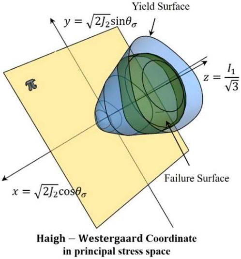
FIGURE 1. Cap model reflecting the yield surface of concrete material in principal stress space.
Based on these fundamental achievements, many researches on the concrete strength were put forward in the last decade. In 2009 and 2011, Zhang etc. (Zhang, 2010; Xu et al., 2011) test on the hybrid steel-polypropylene fiber reinforced concrete (HFRC), and some calculated models of uniaxial compressive and tensile strength of HFRC were proposed. The researches indicated that the steel fiber would significantly the strength of HFRC by maximum increase of 20%, especially tensile strength, while the polypropylene fiber only have a small part to play in the HFRC strength enhancement. Chi etc. (Chi et al., 2014a) based on the Willam-Warner model and the true triaxial test on HFRC, proposed a 3-D general failure model of HFRC, which can describe the yield behavior of HFRC precisely. From 2017 to 2018, Li and Xu etc. (Li et al., 2017; Xu et al., 2018a; Xu et al., 2018b; Xu et al., 2018c; Li et al., 2018) systematically studied the uniaxial tensile and compressive mechanical behavior of HFRC, and many mechanical and damage model of HFRC including uniaxial strength were proposed. In 2018, Liang (2018) studied the stress-strain behavior of plastic concrete under true triaxial experiment. The study indicated that the peak stress in the loading direction would increase significantly by increasing the other principal stresses. In 2019, Yu etc. (Yu et al., 2019; HeMaWang et al., 2021) studied the yield performance and failure mode of self-compacting concrete under biaxial tension. The experimental result show that the lateral tensile stress would influence the failure mode of the material significantly. In 2021, Meng etc. (Meng et al., 2021) studied the conventional triaxial mechanical performance of HFRC, and the action mechanism of confinement and fibers on the triaxial strength of HFRC were revealed. He etc. studied the triaxial strength of high strength concrete (HSC) considering the influence of lateral loading and temperature. The result show that the ratio of triaxial compressive strength to uniaxial compressive strength depends on the stress ratio and temperature level, and an orthotropic constitutive model for HSC under triaxial compression is established, which is in good agreement with the experimental results. Li etc. (Li et al., 2022) studied the yield behavior of recycled aggregate concrete (RAC) under triaxial compression, and corresponding yield model of RAC was proposed in 2022.
These studies have brought theoretical and practical benefits to the application of concrete material in engineering design. However, most of these models are originally targeted at plain concrete, which cannot describe the mechanical behaviors of HFRC quite well, especially the poor reflection of the contribution from the fibers. Moreover, some theoretical models, such as Willam-Warner model, Barcelona model and Ottosen four-parameter model etc., are too complicated to be used in engineering practice, while some empirical models are so simplified that lack adequate accuracy and have defect in universality, which means that some uniaxial strength model cannot be used for the triaxial problem, while some other triaxial model cannot degenerate into the calculation formula of uniaxial strength. To this end, this paper aims to propose a more convenient, accurate and having a certain universality statistical model to predict the axial strength of HFRC under various low lateral confinements. For this purpose, fist, conventional triaxial and true triaxial tests were done for the axial peak stress data, which was selected as the index of the axial strength of the material. Second, based on previous study (Guo and Wang, 1991) the exponential formulae were adopted to fit the test data by least squares analysis, in which the steel fiber and the confinement were selected as the principal factors that influence the axial strength of HFRC (Meng et al., 2021). A total of 108 cylindrical specimens and 225 cubic specimens are designed for conventional triaxial tests and true triaxial tests, respectively. In each type of test, two typical stress paths, i.e., proportionally loading and constant confined loading, are adopted to establish the multiaxial compressive strength model of HFRC. For each stress path, corresponding calculation formulae are proposed based on regression analysis of the test results. Finally, the empirical models were validated with the existing test results.
2 Experimental program
In engineering practice, concrete members are bearing uniaxial compression or low confinement compression. Especially, the applications of confined concrete in contemporary engineering projects make the strength performance and mechanical behavior of concrete materials under complex stress more and more concerned. However, the confinement is generally not tough enough to supply a high lateral pressure to the concrete members in practice. In resulting the lateral stress is far less than the axial stress in the majority of cases when the material yield. Therefore, a series of low confinement pressure of 5–20 MPa were selected as the confinement in the test. In addition, due to the universality and particularity of conventional triaxle stress state, the conventional triaxle test was also carried out in this study independently to the true axial test, for the purpose that increase statistics and pave the way for the establishment of true triaxial strength model of HFRC.
2.1 Specimen design
It has been proved that by dispersing steel fiber into a concrete matrix evenly, a complex constrained network would be formed that can enhance the integrity of concrete and restrain the formation of macro-cracks, which provides a good synergistic effect on improving the concrete mechanical performance (Xu et al., 2011; Chi et al., 2014a; Chi et al., 2014b; Su et al., 2018; Meng et al., 2021). Based on previous studies (Chi et al., 2014a; Su et al., 2018), the volume fraction and aspect ratio of steel fiber (SF) are taken as the variables that would influence the axial strength of HFRC. In this study, the hooked-end steel fibers with the aspect ratio of 30, 60 and 80 respectively were adopted to enhance the mechanical performance of HFRC, as shown in Table 1, and the material properties of polypropylene fibers are also listed in Table 2.
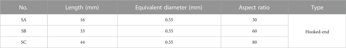
TABLE 1. Physical properties of SF.
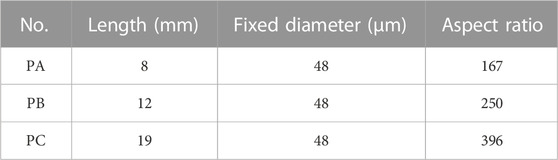
TABLE 2. Physical properties of PF.
Given the levels chosen for the fiber variables and confinements (5–20 MPa), 36 conventional triaxial test groups and 75 true axial test were designed (as shown in Tables 3, 4) based on partial single variable principle. In order to reduce the test error, three specimens have been tested in each group, and then, a total of 111 groups of specimens (108 cylinders for conventional triaxial test and 225 cubes for true triaxial test) were fabricated to investigate the influence of these variables on the axial strength of HFRC under different confinement levels. For convenience, the nomenclature of the specimens was taken as shown in Figure 2, and the fiber information of these specimens for conventional triaxial tests and true triaxial tests are summarized in Tables 3, 4, respectively.
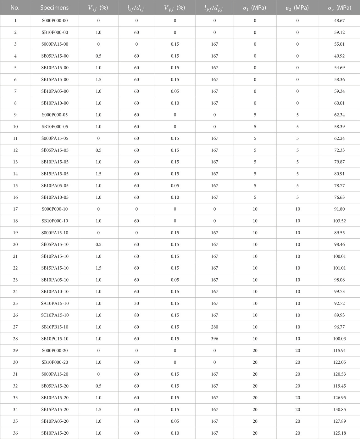
TABLE 3. Axial strength of HFRC under conventional triaxial tests.
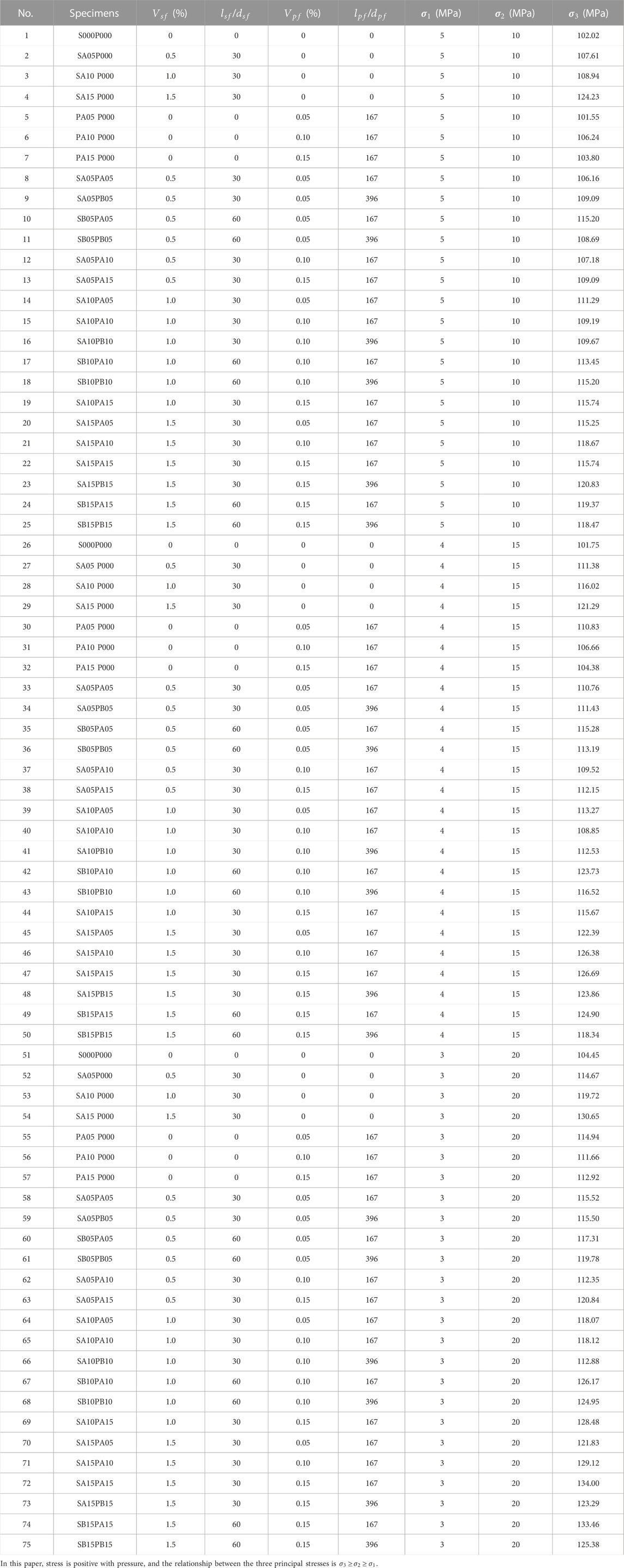
TABLE 4. Axial strength of HFRC under true triaxial tests.
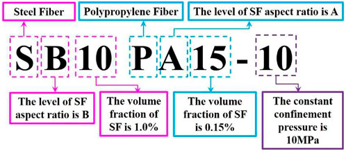
FIGURE 2. Nomenclature of the specimens.
2.2 Specimen fabrication and test setup
To exclude the influence of concrete strength grade, the C50 and C60 grades of HFRC were selected respectively in the conventional triaxial tests and true triaxial tests. The river sand with fineness modulus of 2.8 and the gravel with particle size of 5–15 mm were adopted. The mixture proportions of the concrete matrix are listed in Table 5.
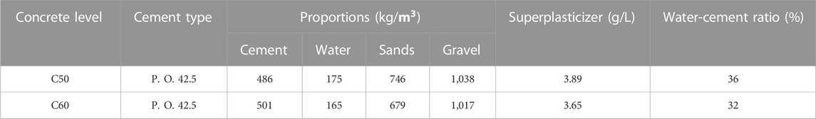
TABLE 5. Mixture proportions of the concrete matrix.
A detail mixing procedure is shown as follows:
(1) Dry cement particles and fine aggregates were added into a mixer and mixed for 120s.
(2) During the step (1), the PF were gradually dispersed into the running mixer carefully to ensure a good distribution of the fibers.
(3) 2/3 of the total amount of water and superplasticizer were added in the mixture and mixed for 120s.
(4) As the cement mortar became consistent and flowable, the SF and the coarse aggregates were then manually dispersed into the mixture. The rest 1/3 water was added into the mixer and mixed for 180s mixing. (5) The fresh HFRC was cast into plastic forms and vibrated through a vibrating table for 3–5 min to compact the material.
The specimens were demoulded after 24 h, and then stored in a curing room with a constant humidity of 95% and temperature of 20°C for 28 days. After that, Φ50 mm × 150 mm cylinders were drilled out from 150 mm × 150 mm × 150 mm standard cubic specimens, and then the specimens were cut by 25 mm from the upper part and bottom of the cylinders, respectively.
In the conventional triaxial test, the MTS 815.3 (full-digitally servo-controlled stiffness testing system) was employed. In order to prevent the oil from dipping into the material due to the formation of a macro crack that may propagate to the surface of the specimen with the evolution of damage, the heat shrinkable tube (HST) was used and wrapped on the surface of the specimen. Furthermore, to reduce the friction resistance, a thin layer of grease was applied between the specimen and the steel column. The extensometers and the radial strain gauge were used to measure the axial strain and lateral strain respectively, as shown in Figure 3A, and a schematic diagram of the installation is shown in Figure 3B. Before the loading, a pre-pressure was applied and held at the fixed value of 0/5/10/20 MPa during the whole loading procedure.
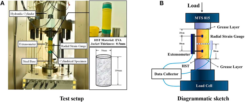
FIGURE 3. Installation of the cylinder HFRC specimen. (A) Test setup. (B) Diagrammatic sketch.
In the true triaxial test, the lateral stress with a value pair of (5 MPa, 10 MPa), (4 MPa, 15 MPa), or (3 MPa, 20 MPa) was applied, respectively, to investigate the influence of lateral stress on the axial strength of HFRC. The true triaxial apparatus was employed and the installation of the cubic HFRC specimens is shown in Figure 4.
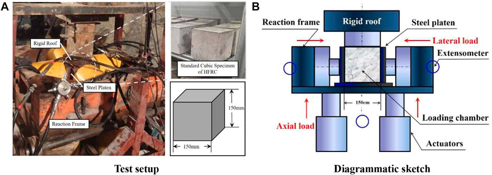
FIGURE 4. Installation of the cubic HFRC specimen. (A) Test setup. (B) Diagrammatic sketch.
2.3 Multiaxial test results
For each group, three identical specimens were tested to reduce the dispersion of test results, and the value of the axial stress at the peak point of the axial stress-axial strain curve was taken as the axial strength of the HFRC specimen, as shown in Figure 5. The axial strength of HFRC of each test group is determined as the average of the axial stress values of three specimens in one group, the results of which are summarized in Tables 3, 4 by follows.
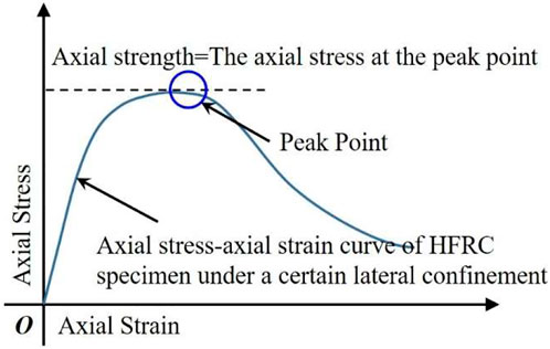
FIGURE 5. Sketch of the definition of axial strength.
2.4 Parameter selection of independent variable
In engineering situations, the passive constraint are the most representative stress states of concrete members, such as FRP confined concrete members. In this situation, with the increase of axial load, the lateral stress tends to increase proportionally to a certain range, and the axial peak stress are positively correlated with the ratio of lateral stress and axial stress. Therefore, the ratio of the principal stresses
3 Axial strength of HFRC under conventional triaxial compression
3.1 Stress ratio-dependent empirical formula
Under some special concrete members, such as confinement concrete members, there would be a certain proportional relationship between the lateral stress and the axial stress, and the ratio of the axial stress and lateral stress is always determined by the confinement coefficient, which can be valued by the member design. Assume that the ratio of lateral stress to axial stress
where
The regression analysis on the experimental results in Table 3 indicates that the parameters in Eq. 1 are a = 0.1735, b = 1.6417 and c = 0.3012, i.e.,
The correlation coefficient R2 between the predictions of the model and the test values is 0.8015.
Taking
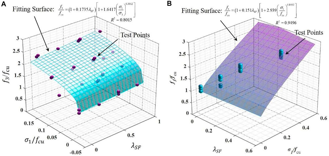
FIGURE 6. Comparisons between the test results and (A) The stress ratio-dependent fitting surface, and (B) The confinement pressure -dependent fitting surface.
The diagram shows that some discreteness between the fitting results and the test values can be observed. This is mainly attributed to the lack of mechanics or physics basis reflecting the causal relationship between the stress ratio and the axial strength. In fact, the mechanism of concrete material yield behavior is the propagation of inner cracks. In this damage process, all of the three principal stresses play a complex role on the cracks evolution, such as the tensile cracks introduced by the tensile stress on some sections and the shear cracks induced by the maximum shear stress on others sections. Mathematically, these principal stresses should usually satisfy some complicated equations, such as W-W yield model (Willam and Warner, 1974; Yin et al., 2014), Barcelona model (Lubliner et al., 1989; Faria et al., 1998; Wu et al., 2006) and so on, rather than the explicit equation between the axial stress and the ratio of lateral stresses, when the material yield. Therefore, due to the lack of the mechanical mechanism of Eq. 2, there would be some intrinsic deviation that hardly can be eliminated. However, even so, the increase of axial strength with the increase of confinement is reasonably reflected by the statistical formula Eq. 2, which can provide a beneficial reference to the engineering construction.
3.2 Confinement pressure-dependent empirical formula
In practice, the HFRC members are usually under passive constraints. However, because of the uncertainty of lateral principal stress in the passive confinement problem, the axial peak stress is hardly mathematically calculated. A functional relation between the axial stress and the lateral stresses can help the calculation of passive confinement problem calculation, and therefore an establishment of active confinement model is valuable. In such cases, a known confining pressure would be the independent variable and the axial strength is a function of confining pressure. For the situation that
where
The diagram of the fitting surface with the test results is shown in Figure 6B, from which it can be seen that compared to the illustration shown in Figure 6A, a satisfactory fitting result with a higher correlation coefficient of 0.9496 is obtained. This is due to the underlying physical mechanism that the concrete material will yield once the principal stresses exceed the critical values, hence, a causal relationship between the axial strength and the confinement pressure makes sense. In many previous achievements of yield model of concrete material, the yield behavior were described as an implicit mathematical form of
4 Axial strength of HFRC under true triaxial compression
4.1 Stress ratio-dependent empirical formula
In the majority of practical situations, the lateral principal stresses are not equal to each other. But even so, a statistical relation between the lateral stresses and the axial stress can be mostly found when the concrete material yield.
When the stress ratios
For the case of
The correlation coefficient

FIGURE 7. Fitting result diagram: (A)
In particular, when
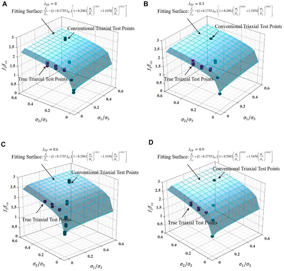
FIGURE 8. Fitting result diagram: (A)
4.2 Confinement pressure-dependent empirical formula
When the two lateral stresses are known as
where
The correlation coefficient is
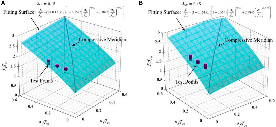
FIGURE 9. Fitting result diagram: (A)
In particular, when
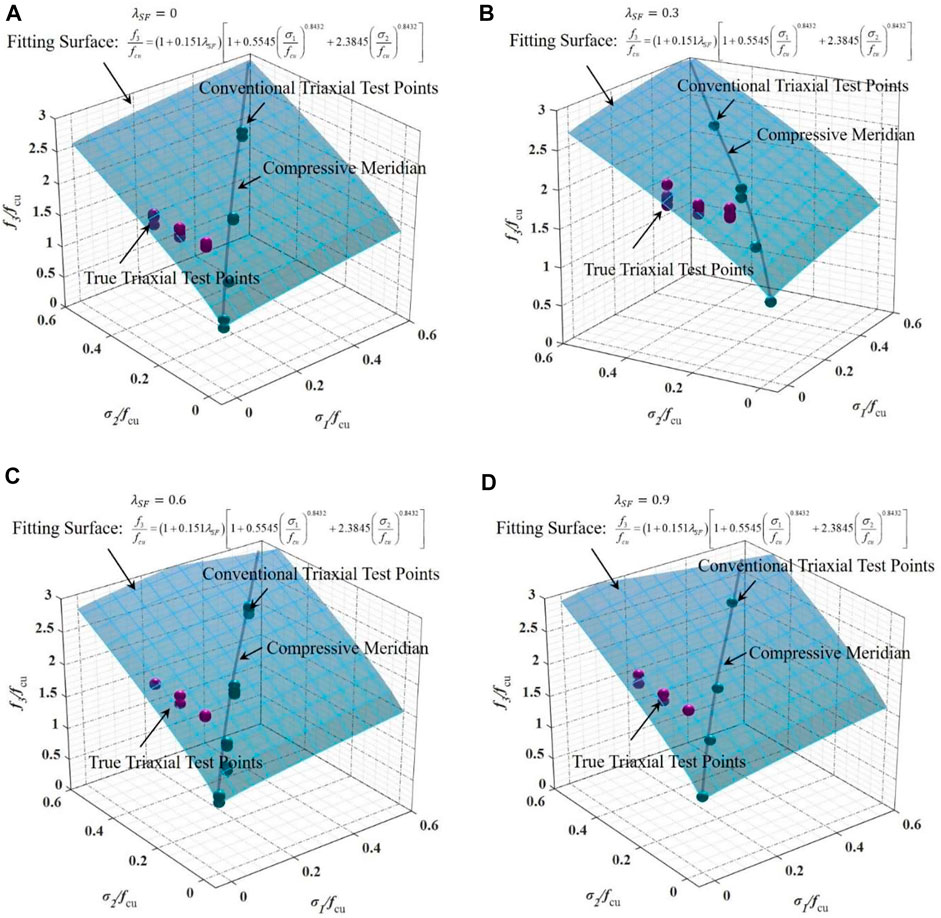
FIGURE 10. Fitting result diagram: (A)
5 Verification and validation
Previous researches (Chern et al., 1993; Xie et al., 1995; Imran and Pantazopoulou, 1996; Chi et al., 2014a) have studied the compressive meridian curve of concrete by conventional triaxial compressive test. The proposed model can be used to describe the meridian of HFRC as well as plain concrete, i.e., in Haigh-Westergaard coordinate, the horizontal ordinate hydrostatic stress
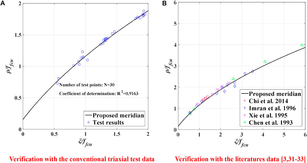
FIGURE 11. Validation and application of the proposed model.
6 Conclusion
In this study, to propose a unified empirical formula to evaluate the multiaxial compressive strength of HFRC, 111 groups of specimens subjected to different confinements were tested. Based on the experimental results and analytical derivations, the following conclusions can be drawn:
1. The addition of hybrid fibers, especially the inclusion of steel fiber, can significantly enhance the axial strength of HFRC under different confinements, and the maximum increase can be up to 20%. While, this enhancement is influenced by the confinement. With increasing confinement level in a certain extent, the enhancement would decrease slightly.
2. Although the failure mode of HFRC under different loading paths may vary, the multiaxial compressive strength (
3. Compared to the stress ratio-dependent model, the prediction of the confinement pressure-dependent model is of higher accuracy, of which the correlation coefficient between prediction results and test data are generally higher than 0.9, probably due to the stronger underlying mechanism.
Altogether, this research tests the yield behavior of HFRC material under conventional triaxial and true axial compressive loading, and proposes a unified compressive strength calculated model for the material, which can fit the test data of this research and previous literature well and be available for the compressive strength prediction of both HFRC material and plain concrete (C30-C60) under uniaxial or triaxial compression with low confinement.
Data availability statement
The original contributions presented in the study are included in the article/supplementary material, further inquiries can be directed to the corresponding author.
Author contributions
JL: Methodology, Formal analysis, Data curation, Validation, Software, Writing—original draft. JH: Writing—review and editing, Validation, Funding acquisition. SL: Investigation, Supervision. YZ: Resources, Software. KM: Conceptualization, Project administration, Writing—review and editing, Supervision.
Funding
Financial support from the Fundamental Research Funds for the Central Universities (Grant No. 2042022kf1056) and the First Construction Engineering Co., Ltd. of China Construction Third Engineering Bureau are gratefully acknowledged.
Conflict of interest
Authors JL, JH, SL, and YZ were employed by First Construction Engineering Co., Ltd. of China Construction Third Engineering Bureau.
The remaining authors declare that the research was conducted in the absence of any commercial or financial relationships that could be construed as a potential conflict of interest.
The authors declare that this study received funding from First Construction Engineering Co., Ltd. of China Construction Third Engineering Bureau. The funder had the following involvement in the study: Formal Analysis, Data Curation, Manuscript Writing, Review & Editing, Validation and Programming.
Publisher’s note
All claims expressed in this article are solely those of the authors and do not necessarily represent those of their affiliated organizations, or those of the publisher, the editors and the reviewers. Any product that may be evaluated in this article, or claim that may be made by its manufacturer, is not guaranteed or endorsed by the publisher.
References
Chern, J. C., Yang, H. J., and Chen, H. W. (1993). Behavior of steel fiber reinforced concrete in multiaxial loading[J]. Aci Mater. J. 89 (1), 32–40.
Chi, Y., Xu, L., Mei, G., Hu, N., and Su, J. (2014). A unified failure envelope for hybrid fibre reinforced concrete subjected to true triaxial compression. Compos. Struct. 109, 31–40. doi:10.1016/j.compstruct.2013.10.054
Chi, Y., Xu, L., and Zhang, Y. (2014). Experimental study on hybrid fiber–reinforced concrete subjected to uniaxial compression. J. Mater. Civ. Eng. 26 (26), 211–218. doi:10.1061/(asce)mt.1943-5533.0000764
Dede, T., and Ayvaz, Y. (2010). Comparative study of plasticity models for concrete material by using different criteria including Hsieh–Ting–Chen criterion. Mater. Des. 31 (3), 1482–1489. doi:10.1016/j.matdes.2009.08.026
Dede, T., and Ayvaz, Y. (2010). Plasticity models for concrete material based on different criteria including Bresler–Pister. Mater. Des. 31 (1), 278–286. doi:10.1016/j.matdes.2009.06.018
Faria, R., Oliver, J., and Cervera, M. (1998). A strain-based plastic viscous-damage model for massive concrete structures. J. 35 (14), 1533–1558. doi:10.1016/s0020-7683(97)00119-4
Guo, Z., and Wang, C. (1991). Study on strength and failure criterion of concrete under multiaxial stress. J] J. Civ. Eng. 024 (003), 1–14. doi:10.1007/BF02919267
HeMaWang, Z. Y. Z., Xiao-jie, Z., Xue-sheng, Z., and Meng-jia, D. (2021). Triaxial strength and deformation characteristics and its constitutive model of high-strength concrete before and after high temperatures[J]. Structures 30, 1127–1138. doi:10.1016/j.istruc.2020.11.078
Hsieh, S. S., Ting, E. C., and Chen, W. F. (1982). A plastic-fracture model for concrete. Int. J. Solids Struct. 18 (3), 181–197. doi:10.1016/0020-7683(82)90001-4
Imran, I., and Pantazopoulou, S. J. (1996). Experimental study of plain concrete under triaxial stress[J]. Aci Mater. J. 93 (6), 589–601.
Li, B., Dai, S., Zhan, Y., Xu, J., Guo, X., Yang, Y., et al. (2022). Strength criterion of recycled aggregate concrete under triaxial Compression: Model calibration. Constr. Build. Mater. 320, 126201. doi:10.1016/j.conbuildmat.2021.126201
Li, B., Xu, L., and Yin, C. (2017). Experimental investigation on the stress-strain behavior of steel fiber reinforced concrete subjected to uniaxial cyclic compression[J]. Beijing: Construction & Building Materials, 140.
Li, B., Yin, C., and Xu, L. (2018). Cyclic tensile behavior of SFRC: Experimental research and analytical model[J]. Constr. Build. Mater. 190, 1236–1250. doi:10.1016/j.conbuildmat.2018.09.140
Liang, F. (2018). Effects of stress-strain behavior of plastic concrete with real strain under true triaxial experiment[J]. J. Water Resour. Archit. Eng. 2018, 250.
Lubliner, J., Oliver, J., Oller, S., and Onate, E. (1989). A plastic-damage model for concrete. Int. J. Solids Struct. 25 (3), 299–326. doi:10.1016/0020-7683(89)90050-4
Meng, K., Yin, C., and Xu, L. (2021). Experimental investigation on the stress-strain behavior of hybrid steel-polypropylene fiber reinforced concrete under conventional triaxial cyclic compression[J]. Beijing: Construction and Building Material.
Ottosen, N. S., and Krenk, S. (1979). Nonlinear analysis of cavities in rock salt. Int. J. Rock Mech. Min. Sci. Geomechanics Abstr. 16 (4), 245–252. doi:10.1016/0148-9062(79)91199-9
Podgórski, J. (1985). General failure criterion for isotropic media. J. Eng. Mech. 111 (2), 188–201. doi:10.1061/(asce)0733-9399(1985)111:2(188)
Song, Y., and He, Z. (2008). Experimental study on strength and deformation properties of high-strength and high-performance concrete under multiaxial compression[J]. J. Rock Mech. Eng. 27 (2), 3575. doi:10.3321/j.issn:1000-6915.2008.z2.041
Su, J., Yin, C., and Meng, K. (2018). Experimental study of strength of steel-polypropylene hybrid fiber reinforced concrete subjected to true triaxial compression[J]. Wuhan: Engineering Journal of Wuhan University.
Willam, K. J., and Warner, E. P. (1974). Constitutive model for triaxial behavior of concrete[J]. Beijing: International Association for Bridge & Structural Engineering Proceeding.
Wu, J. Y., Li, J., and Rui, F. (2006). An energy release rate-based plastic-damage model for concrete. Int. J. Solids Struct. 43 (3-4), 583–612. doi:10.1016/j.ijsolstr.2005.05.038
Xie, J., Elwi, A. E., and Macgregor, J. G. (1995). Mechanical properties of three high-strength concretescontaining silica fume[J]. Aci Mater. J. 92 (2), 135–145.
Xu, L., Li, B., Ding, X., Chi, Y., Li, C., Huang, B., et al. (2018). Experimental investigation on damage behavior of polypropylene fiber reinforced concrete under compression. Int. J. Concr. Struct. Mater. 12 (1), 68. doi:10.1186/s40069-018-0302-3
Xu, L., Li, B., and Yin, C. (2018). Experimental investigation on stress-strain relation of steel-polypropylene hybrid fiber reinforced concrete subjected to uniaxial cyclic compression[J]. J. Build. Eng. 39 (4), 140–152. doi:10.1155/2018/9174943
Xu, L., Xu, H., and Chi, Y. (2011). Experimental study on tensile strength of steel-polypropylene hybrid fiber reinforced concrete[J]. Adv. Sci. Lett. 3, 4. doi:10.1166/asl.2011.1740
Xu, L., Li, B., and Chi, Y. (2018). Stress-strain relation of steel-polypropylene-blended fiber-reinforced concrete under uniaxial cyclic compression[J]. Adv. Mater. Sci. Eng. 2018, 1–19.
Yang, J. Q., and Feng, P. (2020). Analysis-oriented models for FRP-confined concrete: 3D interpretation and general methodology – science direct. J. Eng. Struct. 2020, 216. doi:10.1016/j.engstruct.2020.110749
Yin, C., Xu, L., and Hai-sui, Y. (2014). Constitutive modeling of steel-polypropylene hybrid fiber reinforced concrete using a non-associated plasticity and its numerical implementation[J]. China: Composite Structures, 111.
Yu, M. (1983). Double shear stress criterion for metal plastic deformation[J]. Chin. J. 28 (10), 638–639.
Yu, M., He, L., and Song, L. (1985). Double shear stress strength theory and its extension[J]. Chin. Sci. (Part A Math. Phys. Astronomy Tech. Sci. 12, 55–62.
Yu, M., and Liu, F. (1988). Three parameter criterion of double shear stress and its corner model[J]. J. Civ. Eng. 03, 92–97.
Yu, Z., Huang, Q., and Li, F. (2019). Experimental study on mechanical properties and failure criteria of self-compacting concrete under biaxial tension-compression[J]. J. Mater. Civ. Eng. 31 (5), 04019045. doi:10.1061/(ASCE)MT.1943-5533.0002675
Keywords: hybrid fiber reinforced concrete, steel fiber, polypropylene fiber, multiaxial loading, compressive strength, unified empirical model
Citation: Li J, Hong J, Liu S, Zhou Y and Meng K (2023) Multiaxial compressive strength of hybrid fiber reinforced concrete: A unified empirical model. Front. Mater. 10:1100868. doi: 10.3389/fmats.2023.1100868
Received: 17 November 2022; Accepted: 31 January 2023;
Published: 10 February 2023.
Edited by:
Ramadhansyah Putra Jaya, Universiti Malaysia Pahang, MalaysiaReviewed by:
Majid Ali, Capital University of Science and Technology, PakistanRijalul Fikri, International Islamic University Malaysia, Malaysia
Copyright © 2023 Li, Hong, Liu, Zhou and Meng. This is an open-access article distributed under the terms of the Creative Commons Attribution License (CC BY). The use, distribution or reproduction in other forums is permitted, provided the original author(s) and the copyright owner(s) are credited and that the original publication in this journal is cited, in accordance with accepted academic practice. No use, distribution or reproduction is permitted which does not comply with these terms.
*Correspondence: Kuan Meng, bXJfbWVuZ2t1YW5AMTI2LmNvbQ==