 Yijun Ren
 Xiaolong Wen
 Shengwei Gao
 Bin Ju
- College of Electrical Engineering and Automation, Anhui University, Hefei, Anhui, China
Inductive debris sensor is becoming increasingly important in online oil debris detection. This work proposes a new criterion for evaluating the performance of an inductive oil debris sensor: spatial resolution. When multiple metal particles in lubricating oil simultaneously pass through the sensor, it is vital that clear signals responding to each particle are produced. The spatial resolution is referred to the allowable distance between two particles when the sensor can accurately distinguish the particle signals. Theoretical analysis shows that spatial resolution has a relationship with the output signal of a single particle. A COMSOL model is established to simulate a coil output when two adjacent particles pass, and the output signals change with the distance between two particles, the particle size and the coil structures. Results show that the relevant factors affecting the spatial resolution, and a small coil radius can help improve the sensor’s accuracy of debris identification.
1 Introduction
Mechanical equipment will inevitably wear during their operation. Severe wear may lead to catastrophic consequences especially in aircraft engines and other occasions requiring high safety. It is very important to monitor real-time status of equipment. The information of wear debris in lubrication oil, such as concentration and size, can reflect the wear state of the machines (Flanagan et al., 1988; Zhu et al., 2017). Inductive oil debris sensors are widely used in online lubricating oil condition monitoring of lots of mechanical equipment. The sensor monitors the size and material type of metal particles based on the principle of electromagnetic induction. Compared with other online metal debris monitoring technologies, the inductive sensor has the advantages of simple structure, low cost, and less noise interference.
Relevant studies have found that the amplitude of inductive debris sensor’s voltage signal is proportional to the volume of the particle (Wu et al., 2014a; Ren et al., 2018a). Their correlation coefficient is defined as ‘sensitivity’, and the sensitivity for various designs of sensors is different. High sensitivity means that the sensor can detect very small particles. However, wear debris in the lubrication oil tend to appear agglomerated (Wu et al., 2014b; Chen et al., 2022). It means that when two or more particles pass through the sensor together or with short spatial lengths, their induced voltages will be superposed. And the aliasing signal affects the accuracy of debris identification, especially in conditions of high concentration debris and high flow rate oil (Li et al., 2018a; Liu et al., 2021; Yu et al., 2021). Even though many efforts have been made to improve the sensitivity of inductive debris sensor to the micron level (Du et al., 2013; Hong et al., 2013; Ren et al., 2018b), the signal aliasing may waste this capability and some sensors cannot be practically applied. Several studies have been conducted in an attempt to solve the inaccurate detection caused by mixed particles. Firstly, signal decomposition algorithms have attracted attention to separate each particle signal. Li et al. developed a method by using the degenerate unmixing estimation technique (DUET) on a serial layout of detection sensors (Li et al., 2019). The experimental result showed that this method can effectively separate the mixed particles and provide an accurate count of the particle. Later he studied neural networks for DUET-based delay estimation of wear debris signal separation (Li et al., 2018b). Another Li proposed a method named Ensemble Empirical Mode Decomposition (EEMD), which can decompose the oil signal in time domain and alleviate the influence of noise (Li, 2011). However, there is still no suitable signal processing algorithm to solve the debris signal aliasing in various complicated conditions. In addition to signal processing method, the structure design of the inductive debris sensor greatly influencing sensor performance has also studied. Zhong et al. proposed a new layout of two inductive debris sensors to identify and separate aliasing signal (Zhi et al., 2016). Simulation results indicated that the method was effective. Xiao et al. presented an inductive debris sensor based on a high-gradient magnetic field. The shortest distance between particles that the sensor signals were not superimposed was experimented (Xiao et al., 2019).
In fact, it is insufficient to research on the performance of the inductive debris sensor when multiple particles pass through the sensor with a short distance. The wrong information of wear status may be obtained. So except for sensitivity and allowable throughput, it is important to evaluate the resolution of the sensor to mixed debris. Inspired by geometrical optics, an ideal optical system is affected by light fluctuation and has a resolution limit (Tamburini et al., 2006). According to the Rayleigh criterion, two airy disks that are produced by two close object points are extremely close that the two objects cannot be distinguished by human eyes or optical instruments. Similarly, we propose a parameter ‘spatial resolution’, which refers to the minimum distance between two particles when the corresponding particle signals begin to overlap.
In this paper, the parameter ‘spatial resolution’ is first proposed for evaluating performance of an oil debris monitoring sensor. The theoretical relationship between spatial resolution and model parameters is established. According to COMSOL finite element simulation, the sensor’s spatial resolution can be intuitively demonstrated by observing the signals when particles at a certain distance pass through the coil. Besides, the influence of the coil structure on spatial resolution is further explored.
2 The principle of metal debris detection
According to the Biot–Savart law, the magnetic flux density of any point M(x0, y0, z0) in the coordinate space can be calculated as
where Idl is the current element on line current L, r is the distance between point M and the current element, and μ0 is the permeability of vacuum. As shown in Figure 1A, current I drives a single turn coil with radius R. The coordinate system is established, with the z axis directed along the coil central axis, and the radial direction specified as the x–y axis. The magnetic flux density at any point in the coil can be obtained with Eq. 1.
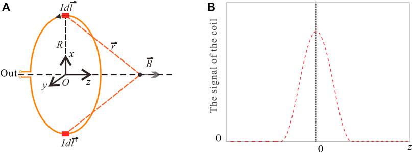
FIGURE 1. (A) Schematic of an energized coil structure, (B) signal signature induced by a metal particle in a single coil.
When the metal debris moves along the z axis, the magnetic flux density varies. When no particles pass through, the original magnetic flux density is defined as B0. B0 can be expressed as
As long as particles enter the oil pipe, the magnetic flux density changes with the movement of the particles. A spherical particle could be equivalently expressed by a magnetic dipole model, the magnetic flux density generated by a particle is
where
Thus, the magnetic flux can be derived as
Finally, the change in coil inductance can be expressed as
Here, the signals are ideal without considering complicated noise effects. As demonstrated in Figure 1B, a pulse output can be obtained when a metallic particle passes through the coil. The amplitude of the pulse signal is related to the particle’s size. It is one of the most important parameters for judging the sensor’s sensitivity.
3 The spatial resolution of inductive debris sensor
In addition to sensitivity, spatial resolution is also important for wear debris sensor. If two particles pass successively through the coil, their induced signals may affect each other and even overlap, as shown by the red line in Figure 2. When these two particles pass through separately, their normal signals are shown in the dotted line in the figure. The overlapped signal (the red line) is required to have two peaks to determine the number and size of particles accurately, and the amplitude is required to be nearly unchanged. The spatial resolution parameter is regarded as an evaluation criterion that determines if the detection system can distinguish the signals corresponding to two adjacent particles. In other word, it is the minimum distance between two distinguishable particles. Evidently, if the signal of single particle output by sensor probe is steep, these will be beneficial to reduce the degree of signal aliasing and the spatial resolution performance is improved.
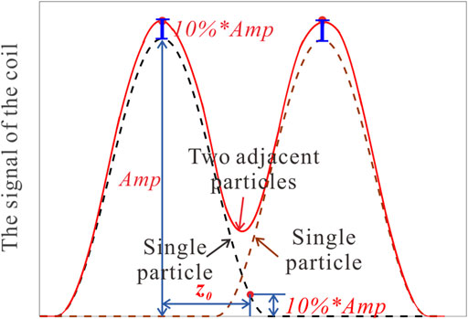
FIGURE 2. Schematic of the output signal induced by two metal particles in a single coil.
According to the characteristics of the coil’s output signal induced by particles, two identical debris are used to define the spatial resolution. As shown in Figure 2, the amplitude of the signal induced by a single particle is denoted as Amp. The amplitude of the aliasing signal induced by two adjacent particles is allowed to change within 10%*Amp relative to that of a single particle. The parameter z0 is defined as the distance between the signal peak and the 10% the signal peak point, and the spatial resolution P is related to the parameter z0. If the distance between two particles is less than z0, the amplitudes of signal peaks corresponding to the two particles will exceed 10%*Amp, thereby influencing the judgment of particle size. Here, spatial resolution is defined as
According to Eqs 5, 6 in the previous section, the amplitude Amp of the pulse signal is determined by the coil design and the particle properties. The parameter z0 is also affected by these factors. Thus, the relationship between them can be briefly expressed as
where d is the distance between two adjacent particles, r is the particle’s radius. Their impacts on the spatial resolution are respectively analyzed by the following simulations.
4 The simulation analysis of the spatial resolution
A simulation model of particles passing through the coil is built with the COMSOL software to show the overlapping degree of the output signals induced by two particles. By using a 3D model, the model of the coil is set as a one-turn coil with a 4.5 mm radius. The radius of the copper wire is 0.1 mm. The distribution of the magnetic field in the coil excited with a 2A alternating current is shown in Figure 3. The excitation frequency is set to 150 kHz, and the initial inductance of the coil is calculated as L0. As iron particles pass through the coil, corresponding disturbance of the magnetic field leads to changes in coil inductance.

FIGURE 3. 3D drawing of the magnetic field in the energizing coil.
4.1 Spatial resolution on central axis of coil
When a particle with a radius of 0.5 mm moves along the central axis of the pipe, the relative variation in the coil’s inductance (L-L0)/L0 is shown in Figure 4A. The particle moving to the center of the coil exerts the greatest influence on the magnetic field, and the maximum change in coil parameters occurs. When the signal decreases to 10% of the peak value, z’0 is approximately 5 mm. Hence, spatial resolution P can be inferred as 5 mm.
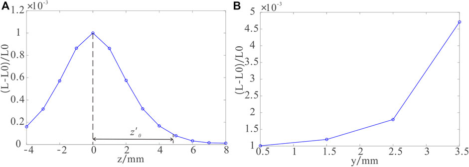
FIGURE 4. (A) Change in coil inductance when a particle moves along the central axis of the coil and (B) change in coil inductance when a particle moves radially toward the coil.
Figure 4B shows the relative variation in coil inductance when the particle at the coordinate origin moves along the Y direction. As the particle approaches the copper wire, coil inductance increases rapidly. The particle at the center of the coil minimally disturbs the magnetic field.
The model wherein two identical particles successively pass through the coil is simulated to observe the aliasing signal. When two particles with an axial distance of d flow along the central axis of the pipe, the change in coil inductance is shown in Figure 5. The coil’s output signals vary with the change in the axial distance d. The signals of two particles overlap when d is 2 and 3 mm. Their output signal has only one peak; thus, distinguishing the two particles is nearly impossible. When d increases to 4mm, the two particles can be distinguished. However, the amplitude corresponding to z = 0 is more than 10% Amp, and the position of the signal peak deviates from z = 0. The overlapped signal is also seriously distorted. When d is equal to 5 mm, the amplitudes of the two peaks are close to the amplitude of the signal induced by a particle. The number and size of the two flowing particles can be judged. Thus, the spatial resolution P is verified.
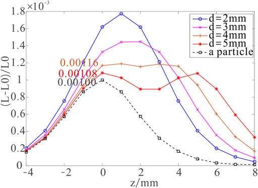
FIGURE 5. Coil output signals when two particles located on the central axis with a distance of d pass through the coil.
4.2 The relationship between spatial resolution and radial position of debris
A particle’s trajectory in the pipe is irregular, and not all particles are distributed on the central axis. The signals induced by the particles deviating from the central axis must be considered. Figure 4B shows the relative variation of coil inductance when the particle at the coordinate origin moves along the Y-direction. As the particle approaches the copper wire, the coil inductance increases rapidly. Relatively, the particle at the center of the coil disturbs minimally the magnetic field. The situation wherein two particles successively passing through the coil deviate from the central axis by 3 mm is simulated. The axial distance d between two particles is changed. As shown in Figure 6, the relative variation in coil inductance is different from that induced by particles along the central axis.
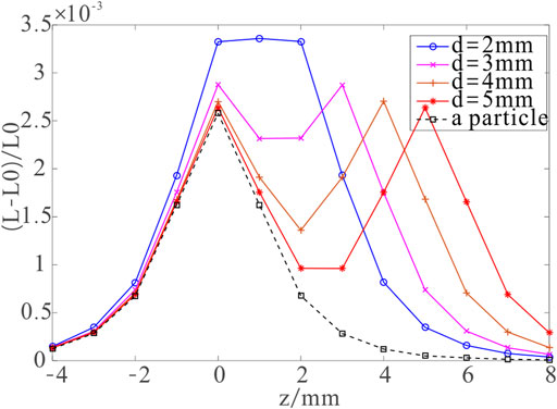
FIGURE 6. Coil output signals when two particles deviating from the central axis by 3 mm with a distance of d pass through the coil.
Compared with Figure 5, the output signal induced by a single particle in Figure 6 has higher amplitude, and the signal curve is steeper. No serious overlap is observed for the signals corresponding to two particles when the two particles pass through the coil. It is easy to identify two adjacent particles. Therefore, due to the more serious signal aliasing degree, the situation at the central axis needs to be analyzed. It is more suitable to reflect the spatial detection capability of the sensor.
4.3 The relationship between spatial resolution and debris size
Aside from the distance between two particles passing successively, the influence of particle size on the coil’s output signals is also studied. Two particles with an axial distance of 5 mm flowing along the central axis of the pipe are simulated. The relative variation in coil inductance (L-L0)/L0 caused by the change in particle size is shown in Figure 7. The signal amplitude increases with the size of the particles. However, the overlap degree of the signals induced by the two particles is hardly changed under the different particle sizes. The bandwidths of the signals are almost identical. In this case, the signals are ideal without considering complicated noise effects. Hence, particle size does not exert much effect on judging the sensor’s spatial resolution.
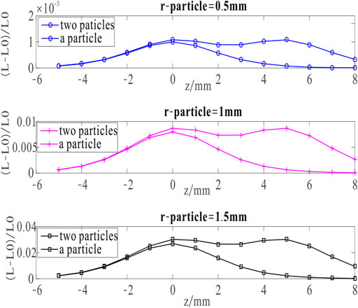
FIGURE 7. Influence of different particle sizes on the relative variation in coil inductance (L-L0)/L0.
4.4 The relationship between spatial resolution and coil size
Different sensor coils induce different signals and greatly influence the spatial resolution. A 3D model wherein the particles move along the central axis is established, and the distance d between two particles is changed. When coil radius R varies, the relative variation in coil inductance (L-L0)/L0 is shown in Figure 8. As the coil radius increases, the amplitude of the signal induced by a particle decreases, and the bandwidth becomes wide. The result also shows that a larger coil radius R indicates severer signal overlapping when two particles pass through the coil. Therefore, the spatial resolution of the sensor worsens when the coil radius increases. The design of the sensor also needs to meet the throughput requirements in practical applications. According to a previous study, the pipe diameter of several common inductive debris sensors is roughly in the range of 4mm–38 mm (MACOM Technologies Documentation, 2019; Poseidon Systems Ltd, 2019; HYDAC Documentation, 2022). It is found that a large pipe’s radius can allow high throughput but low detection sensitivity. The reasonable design of coil structure is in great urgent to not only obtain a large throughput, but also ensure high sensitivity and spatial resolution. The accuracy of metal debris monitoring can be guaranteed in practical application.
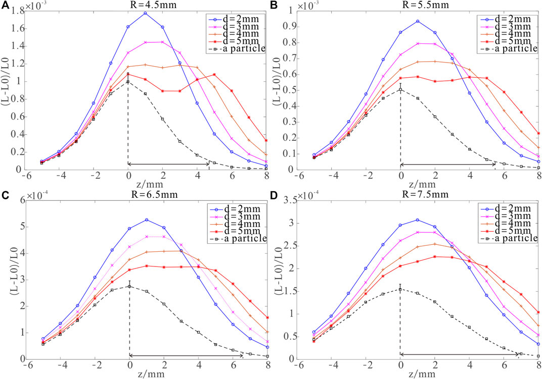
FIGURE 8. Influence of variable coil radius R on the coil’s signals induced by two adjacent particles on the central axis. (A) R = 4.5 mm, (B) R = 5.5 mm, (C) R = 6.5 mm, (D) R = 7.5 mm.
5 Conclusion
The spatial resolution parameter for inductive debris sensors is first clarified in this study. In practical engineering applications, many particles are randomly distributed in the lubricating oil of machines. In addition to sensitivity and allowable throughput, spatial resolution is an important parameter to be considered when evaluating the performance of oil debris monitoring systems. On the basis of the signal characteristics of inductive debris sensors, spatial resolution in this study is defined. Finite element simulation is performed to reveal the signal characteristic of two particles at a certain distance. The influence of particle trajectory and its properties on signal aliasing degree is explored. The conditions of two particles moving along the central axis of coil and on other axes near the coil are compared, and indicate that signal aliasing is the most serious on the central axis. Without considering complicated noise effects, the situations of signals aliasing are not considerably influenced by particle size. Moreover, the results verify that the design of the sensor coil greatly affects the spatial resolution. The higher the spatial resolution is, the smaller the allowable distance between distinguishable particles is and the less likely the signals are to be aliased. The spatial resolution parameter combined with sensitivity and throughput can help in the design of sensor structures and in the accurate evaluation of the oil debris information. Overall, this parameter is meaningful in reducing the detection limit of inductive wear debris sensors in practical applications.
Data availability statement
The original contributions presented in the study are included in the article/supplementary material further inquiries can be directed to the corresponding author.
Author contributions
YR proposes the topic idea and arranges this work. XW conducts theoretical analysis. SG conducts simulation analysis. YL and BJ offer revision advices.
Funding
This work was supported by Anhui Provincial Natural Science Foundation (2208085QE157) and College Natural Science Research Key project of Anhui Education Department (KJ2021A0008).
Conflict of interest
The authors declare that the research was conducted in the absence of any commercial or financial relationships that could be construed as a potential conflict of interest.
Publisher’s note
All claims expressed in this article are solely those of the authors and do not necessarily represent those of their affiliated organizations, or those of the publisher, the editors and the reviewers. Any product that may be evaluated in this article, or claim that may be made by its manufacturer, is not guaranteed or endorsed by the publisher.
References
Chen, S., Cao, N., Zhang, W., and Yu, B. (2022). Separation of aliasing signals from inductive oil debris monitors based on fully convolutional neural networks. Meas. Sci. Technol. 33 (11), 115016. doi:10.1088/1361-6501/ac7f1c
Du, L., Zhu, X., Han, Y., and Zhe, J. (2013). High throughput wear debris detection in lubricants using a resonance frequency division multiplexed sensor. Tribol. Lett. 51 (3), 453–460. doi:10.1007/s11249-013-0179-x
Flanagan, I. M., Jordan, J. R., and Whittington, H. W. (1999). An inductive method for estimating the composition and size of metal particles. Meas. Sci. Technol. 1 (5), 381–384. doi:10.1088/0957-0233/1/5/001
Flanagan, I. M., Jordan, J. R., and Whittington, H. W. (1988). Wear-debris detection and analysis techniques for lubricant-based condition monitoring. J. Phys. E Sci. Instrum. 21 (11), 1011–1016. doi:10.1088/0022-3735/21/11/001
Hong, W., Wang, S. P., Shi, J., and Han, L. (2013). Radial inductive debris detection sensor and performance analysis. Meas. Sci. Technol. 24 (12), 125103. doi:10.1088/0957-0233/24/12/125103
HYDAC Documentation (2022). Metallic contamination sensor, MCS 1000 series. Available from: https://www.hydac.com/de-en/products/sensors/contamination-sensors/mcs1000/show/Download/index.html.
Li, T., Wang, S., Enrico, Z., Shi, J., and Hong, W. (2018). Aliasing signal separation of superimposed abrasive debris based on degenerate unmixing estimation technique. Sensors 18 (3), 866. doi:10.3390/s18030866
Li, T. Y., Wang, S. P., and Ma, Z. H. (2018). “Simulation on neural networks for DUET-based delay estimation of abrasive debris signal separation[C],” in CSAA/IET International Conference on Aircraft Utility Systems (AUS 2018), Guiyang, China, June 19–22, 2018.
Li, T. Y., Wang, S. P., and Yang, Z. (2019). “Aliasing signal separation for superimposition of inductive debris detection using CNN-based DUET,” in 2019 14th IEEE Conference on Industrial Electronics and Applications (ICIEA), Xi'an, China, 19-21 June 2019 (IEEE).
Li, Z. D. (2011). An Ensemble empirical Mode decomposition approach to wear particle detection in lubricating oil subject to particle overlap. Canada: University of Ottawa.
Liu, H., Li, T., Hong, W., and Wang, S. (2021). Using multi-window correlation to improve sensitivity and adaptability for oil debris detections. Measurement 176, 109236. doi:10.1016/j.measurement.2021.109236
MACOM Technologies Documentation (2019). TechAlert™ 10, inductive wear debris sensor with water/air screening [M]. Available from: http://www.macom.co.uk/ta10.pdf.
Poseidon Systems Ltd (2019). Documentation TRIDENT™ DM4500, Wear Debris Monitor, Realtime monitoring leads to improved asset health management [M]. Available from: https://www.poseidonsys.com/downloads/brochures/dm4500-brochure.pdf.
Ren, Y. J., Wei, L., and Feng, Z. G. (2018). Inductive debris sensor using one energizing coil with multiple sensing coils for sensitivity improvement and high throughput. Tribol. Int. 128, 96–103. doi:10.1016/j.triboint.2018.07.025
Ren, Y. J., Zhao, G. F., and Qian, M. (2018). A highly sensitive triple-coil inductive debris sensor based on an effective unbalance compensation circuit[J]. Meas. Sci. Technol. 30 (1), 015108. doi:10.1088/1361-6501/aaf119
Tamburini, F., Anzolin, G., Umbriaco, G., Bianchini, A., and Barbieri, C. (2006). Overcoming the Rayleigh criterion limit with optical vortices. Phys. Rev. Lett. 97 (16), 163903. doi:10.1103/physrevlett.97.163903
Wu, H., Wu, T., Peng, Y., and Peng, Z. (2014). Watershed-based morphological separation of wear debris chains for on-line ferrograph analysis. Tribol. Lett. 53 (2), 411–420. doi:10.1007/s11249-013-0280-1
Wu, T., Wu, H., Du, Y., Kwok, N., and Peng, Z. (2014). Imaged wear debris separation for on-line monitoring using gray level and integrated morphological features. Wear 316 (1-2), 19–29. doi:10.1016/j.wear.2014.04.014
Xiao, H., Wang, X., Li, H., Luo, J., and Feng, S. (2019). An inductive debris sensor for a large-diameter lubricating oil circuit based on a high-gradient magnetic field. Appl. Sci. 9 (8), 1546. doi:10.3390/app9081546
Yu, B., Cao, N., and Zhang, T. (2021). A novel signature extracting approach for inductive oil debris sensors based on symplectic geometry mode decomposition. Measurement 185, 10056. doi:10.1016/j.measurement.2021.110056
Zhi, Z., Wang, S., and Wei, H. (2016). “Aliasing signal separation of oil debris monitoring,” in 2016 IEEE 11th Conference on Industrial Electronics and Applications (ICIEA), Hefei, China, 05-07 June 2016 (IEEE).
Keywords: inductive debris sensor, spatial resolution, sensitivity, signal aliasing, adjacent particles
Citation: Ren Y, Wen X, Gao S, Liu Y and Ju B (2023) Theoretical and simulation analysis on the spatial resolution of magnetic metal debris sensors. Front. Mater. 10:1110834. doi: 10.3389/fmats.2023.1110834
Received: 05 December 2022; Accepted: 20 February 2023;
Published: 07 March 2023.
Edited by:
Yang Yu, University of New South Wales, AustraliaReviewed by:
Zine Ghemari, University of M’sila, AlgeriaGuofeng Zhao, University of Science and Technology of China, China
Copyright © 2023 Ren, Wen, Gao, Liu and Ju. This is an open-access article distributed under the terms of the Creative Commons Attribution License (CC BY). The use, distribution or reproduction in other forums is permitted, provided the original author(s) and the copyright owner(s) are credited and that the original publication in this journal is cited, in accordance with accepted academic practice. No use, distribution or reproduction is permitted which does not comply with these terms.
*Correspondence: Yijun Ren, cmVueWpAYWh1LmVkdS5jbg==