 Jia Liu1
 Deluan Feng2*
- 1CCCC Bay Area, Investment and Development Co., Ltd, Guangzhou, China
- 2School of Civil and Transportation Engineering, Guangdong University of Technology, Guangzhou, China
Soil-rock mixture is a complex multi-phase composite geotechnical material, and its strength is determined by the physical properties of constituent multi-phase materials and their coupling mechanical response between different phases of materials. Based on the Eshelby-Mori-Tanaka equivalent inclusion average stress principle, a theoretical model of multi-scale coupled shear strength of soil-rock mixture considering the interaction effect of rock block and soil is established, and the rotational freedom reflecting the microscopic motion details of rock block is introduced. Moreover, a multi-scale coupled constitutive relationship of soil-rock mixture is derived and compiled into a multi-scale finite element program. Based on the large-scale direct shear test of soil-rock mixture, the model parameters of the multi-scale finite element method are determined, and then the multi-scale finite element program is used to simulate and predict the cross-scale deformation process of the soil-rock mixture slope. The results show that the multi-scale finite element method can effectively describe the influence of the mechanism of the micro motion characteristics of the soil-rock mixture on the macro mechanical response, and can effectively overcome the pathological mesh-dependency of the classical finite element method; the rotation displacement of the rock block is mainly concentrated within the shear zone of the slope. The maximum rotational displacement of rock blocks inside the soil-rock mixture slope is 40.7°, and the rotational displacement of rock blocks outside the shear zone is about 0°. The physical mechanism of the cross scale evolution of the shear band of the soil-rock mixture slope is that: the rotation of the rock blocks weakens the strain transmission ability between the rock block and the matrix soil, thus forming the concentration and development of the plastic strain, and finally leading to the penetration of the shear bands of the slope and the overall sliding failure.
1 Introduction
The finite element method is an effective numerical method for solving boundary value problems in solid mechanics (Strouboulis et al., 2001), and has been widely applied in geotechnical engineering problems such as foundation pit design, tunnel engineering, foundation treatment and slope stability analysis (Collinswilliams 2015; Liu et al., 2015; Cai et al., 2020; Mikkelsen et al., 2022). However, the soil-rock mixture has the heterogeneous and discontinuous nature of multiphase of solid particles at different scales, water and air. When the classical elastic-plastic finite element method based on the principle of continuum mechanics is used to analyze and calculate geotechnical engineering problems, it often produces large deviations, such as the pathological mesh-dependency of the prediction results and the difficulty in convergence of the solution process (Broumand and Khoei 2013). The mechanical properties of the particle interface and the particle interior of the soil-rock mixture are completely different. Even under uniform stress condition, the deformation across the interface will be discontinuous. Therefore, the deformation and strength characteristics of soil-rock mixture are significantly different from those of the continuous medium. The discontinuity of the deformation of the soil-rock mixture is caused by the discontinuity of its internal structure and the physical properties of particle characteristics, that is, the natural granularity and structure of the soil-rock mixture make it a discontinuous medium. The mechanical properties of the discontinuous medium are usually highly nonlinear, with nonlinear characteristics such as deformation localization, parameter sensitivity and system catastrophe (Fang and Li 2016). The classical soil mechanics treats the soil-rock mixture as a homogeneous continuous medium, which embeds the assumptions of continuity, material homogeneity and physical mechanism consistency, and correspondingly neglects the natural granularity, structure, multiphase and mechanical mechanism couplings of the soil-rock mixture at different scale structure levels. Only for small uniform deformation, it is possible to obtain approximately reasonable theoretical results, and significant errors will occur in the analysis and prediction of the generation and development of large deformation shear bands closely related to the particle size and structure of soil-rock mixture (Tang et al., 2018). For example, when the classical elastic-plastic finite element method based on the principle of macro continuum mechanics simulates the evolution of shear bands, its prediction results strongly depend on the size of the mesh and show significant pathological mesh-dependency (Soltani and Maekawa, 2015; Chang et al., 2021). Therefore, the simulation and prediction results of the mechanical response of the soil-rock mixture with natural multiscale coupling characteristics by the classical elastic-plastic finite element method cannot conform to the physical reality and lose objectivity. The reason is mainly reflected in two aspects. At the physical level, the classical elastic-plastic finite element method regards the soil-rock mixture as a uniform continuous medium, and neglects the influence of the mechanism of the physical details and motion characteristics of the soil-rock mixture at the micro level on the macro mechanical response; At the mathematical level, when the softening constitutive relation is used to describe the cross-scale deformation process of the soil-rock mixture slope in the classical elastic-plastic finite element method, its control partial differential equation loses its positive definiteness (Arriaga et al., 2015).
With the development of the research in the interdisciplinary field of computer science and computational mechanics, the finite element method has made great progress in simulating and predicting the multiscale coupled mechanical response of the deformation failure process of soil-rock mixtures. Plenty of previous studies have focused on the use of finite element method for prediction of the mechanical responses of the soil-rock mixture. Recently, some finite element methods that can describe the microstructure characteristics of the soil-rock mixture by dividing it into rock blocks and soil matrix have appeared (Guo and Zhao, 2015; Guo et al., 2021). The ideas of these macro and micro finite element analysis methods can be divided into two categories. One is to theoretically construct various representative elements that can reflect the microstructure characteristics of rock blocks and soil matrix. For example, Goodman et al. (1968) constructed a joint element that describes the discontinuity of rock mass and evaluated the impact of mechanical properties of joints on the strength and stability of rock mass; Ling and Ye (2005) constructed a plane coordinated manifold soil element to describe the consolidation characteristics of soil and predicted the settlement and pore water pressure distribution of the riverbed; Li and Wan (2011) constructed a micropolar element reflecting the rotational displacement of soil particles and analyzed the micromechanism of soil strain localization; Liang and Zhao (2019) constructed a representative element reflecting the micro structure characteristics of soil particles and simulated the multiscale coupled evolution process of large deformation of soil-rock mixture. The other is to directly capture the micro physical details of the soil-rock mixture by various imaging methods and reconstruct them into files recognizable by the finite element program by digital image processing technology. For example, Xu et al. (2008) obtained the material information of the soil-rock mixture by using an optical camera and analyzed the influence of the micro structure characteristics of the soil-rock mixture on its macro strength characteristics through the combination of digital image processing technology and finite element method; Zheng et al. (2014) used nuclear magnetic resonance technology to characterize the material composition and combined with finite element method to simulate and predict the nonlinear mechanical response of materials; Bubeck et al. (2017) used CT scanning technology to determine the shape characteristics of pores in rocks, and combined with finite element method to study the influence of different pore shapes on the strength of geomaterials.
Although the above-mentioned researches have preliminarily explored the establishment of finite element method considering the micro motion details and structural characteristics of soil-rock mixture and achieved certain results, the model parameters involved do not have clear physical meanings. Meanwhile, the theoretical basis of these research results is still based on the phenomenological uniform continuum mechanics at the macroscale, which fails to break through the limitation that the classical constitutive model of soil-rock mixture cannot describe the coupling of mechanical responses of soil-rock mixture at different scale structure levels. Therefore, it is impossible to scientifically simulate and predict the cross-scale coupling correlation characteristics of the influence of the micro motion details of rock and soil particles at different scale on the macro mechanical response in the deformation process of the soil-rock mixture from the physical nature and physical mechanism. Therefore, Feng and Fang (2015a, 2015b) established a multiscale soil cell model of cohesive soil containing sand based on the coupled stress theory for the micro motion details of clay particles and sand particles, but only gave a complex theoretical solution, which has not been promoted to the engineering application level. In this paper, based on the idea of the soil cell model, the multiscale coupled constitutive relationship embedded the rotational freedom of soil-rock mixture is derived. Using the user subprogram interface of ABAQUS finite element program UEL, a multiscale coupled finite element program considering the rotational freedom of the element is compiled to quantitatively analyze the influence of rock block content on the cross-scale evolution process of the soil-rock mixture slope, In order to lay a solid foundation for the direct application of multiscale coupled finite element method to solve geotechnical engineering problems closely related to particle size characteristics of the soil-rock mixture.
2 Theoretical basis of multi-scale mechanics of soil-rock mixture
2.1 Mesoscopic representative volume element (RVE) of soil-rock mixture
For geotechnical engineering problems, it is unrealistic and unnecessary to conduct detailed and complete simulation for each solid particle on the micro scale. Establishing a new constitutive relationship under the continuous medium mechanics framework considering the influence of mesostructure characteristics of soil-rock mixture has become an effective way to simulate and predict the shear strength of soil-rock mixture. In fact, the macroscopic deformation and failure of the soil-rock mixture are mainly determined by the rock block (Li et al., 2016; Wang et al., 2020). Therefore, according to the physical and mechanical effects of the interaction of soil particles and rock blocks of the soil-rock mixture at different scales, the soil-rock mixture is divided into soil matrix and rock blocks, and a representative volume element (RVE) is constructed at the mesoscale, which is large enough compared with the local microstructure volume element size but small enough compared with the whole soil-rock mixture layer in the engineering scale. According to previous studies (Zhang et al., 2016; Du et al., 2017; Yang et al., 2021), the soil/rock threshold of 5 mm can be selected. Therefore, particles with diameters smaller than 5 mm are referred to as soil particles; those with diameters larger than 5 mm are referred to as rock blocks. In the RVE, the soil particles interact with the pore water to form a soil matrix, and the rock block is regarded as a rigid sphere, as shown in Figure 1.
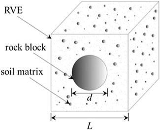
FIGURE 1. The representative volume element of soil-rock mixture.
It is assumed that the rock block is a rigid sphere and is wrapped by the soil matrix. Each rock block and its adjacent matrix soil form a cubic cell, as shown in Figure 1. Therefore, the volume of the RVE is L3 and the volume of the rock block is πd3/6. The side length L can be expressed as (Feng and Fang 2015c; 2016):
where d is the particle size of the rock block; α is the rock block content, and denotes the ratio of the volume of the rock block to the total volume of the soil-rock mixture sample; Here, in order to make the soil-rock mixture sample have the soil-rock cell structure, the length L of the cube cell has to be larger than the diameter d of the equivalent spherical rock block. According to Eq. 1:
2.2 Multi-scale coupled shear strength theoretical model of soil-rock mixture
Different structural levels of soil-rock mixture show different mechanical responses. The rock blocks mainly translate and rotate, while the matrix mainly produces microcracks (Wang et al., 2018; Zhao and Zhou 2020). Moreover, there are extremely complex phase to phase coordinated deformation and interface interaction between the soil matrix and the rock block, which makes the stress transfer, crack evolution and failure characteristics of the soil-rock mixture different from those of the pure soil and rock.
When subjected to external loads, the soil-rock mixture, whose skeleton is composed of mineral particles of cross grain group scale, shows that the contact bond and cementation bond between the matrix particles are broken and microcracks are generated at the microscale (Feng and Fang, 2016); at the mesoscale, it is shown that the plastic shape distortion of the soil matrix is induced by the incompatible deformation between the soil matrix and rock block in the soil-rock cell; at the macroscale, it shows complex engineering mechanical behaviors such as nonlinear and zigzag stress-strain relationship of the soil-rock mixture (Xu et al., 2011). Therefore, the mechanical behaviors of soil-rock mixtures at different scales are not only coupled and related to each other, but also have certain independence. As a meso RVE reflecting the basic mechanical effects and particle characteristics of soil-rock mixtures, the soil-rock cell is the key factor to establish a multiscale framework for the soil-rock mixture.
For the soil-rock cell, the natural granular and structural characteristics of the soil-rock mixture at the microscale cause its internal deformation to show significant discontinuity and nonlinearity, which is manifested as the gradient phenomenon of shear strain of the soil matrix connecting the rock block (Feng and Fang 2016). Strain gradients occur when the microstructures of the material undergo plastic shape distortion. Therefore, the strain gradient theory is used to describe the plastic shape distortion inside the soil-rock cell in this study, and then the strain energy of the soil-rock cell can be expressed by the strain and the strain gradient (Fang 2014; Feng and Fang 2015c):
and
where
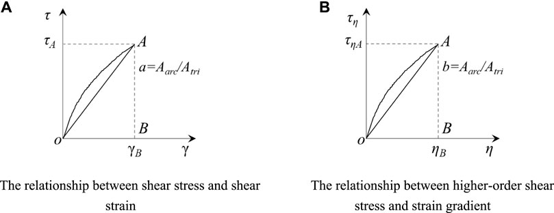
FIGURE 2. Physical meanings of parameters (A, B).
A concise theoretical model for calculating the shear yield stress of the meso representative volume elements can be obtained from Eq. 2–4:
and
and
where
where L is the side length of the volume element represented by the meso cube of the soil-rock mixture; d is the particle size of the rock block;
In the soil-rock mixture, the diameter of the rock blocks is varying, therefore, the average strain gradient of the soil-rock mixture can be calculated by the grading function of the rock blocks, one may find:
where
Eq 5 is a concise theoretical model of predicting the multiscale coupled shear strength of soil-rock mixture. However, the mechanical response of the soil matrix inside the soil-rock cell is different from that of the pure matrix due to the influence of the rock block, and the stress-strain relationship of the matrix inside the soil-rock cell is difficult to determine. According to the purpose of dividing the soil-rock mixture in to soil matrix and rock block, for the practical application of Eq. 5, the following two problems still have to be solved through theoretical analysis: (1) how the shear stress and shear displacement relationship
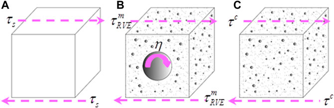
FIGURE 3. The stress state of the soil-rock mixture, RVE and the pure soil matrix. (A) soil-rock cell; (B), RVE ingredients; (C) pure soil matrix.
2.3 Eshelby-Mori-Tanaka equivalent inclusion average stress principle
Hu et al. (2013) and Fang et al. (2013) have respectively derived the effective elastic modulus of pebble soil and the equivalent effect gradient of cohesive soil by using the Eshelby equivalent inclusion principle, and obtained good theoretical results. According to Eshelby equivalent inclusion principle (Eshelby 1957), the shear stress of the soil matrix and the rock block in the representative volume element (RVE) of the soil-rock mixture can be expressed as:
where
where S is Eshelby constant, T is hill constant, and S + T = 1 (Hill 1963; Weng 1984);
For ellipsoidal rock block (spherical is its special case), Eshelby constant can be expressed as:
where
Combining Eqs. 11–14, one may find:
Substituting Eqs 11, 17 into Eq. 12, yields:
According to the Mori Tanaka average stress method (Mori and Tanaka 1973), the average stress remains unchanged, the shear stress of the soil matrix can be expressed as:
According to Eq. 21, one may find:
Substituting Eq. 22 into Eq. 20, yields:
Substituting Eq 12, 21 into Eq. 11, one may find:
and
Substituting Eqs 23, 24 into Eq. 11, yield:
It can be seen from Eq. 27 that the occurrence of rock block causes stress concentration in the adjacent soil matrix, and the corresponding stress concentration coefficient
Combining Eqs 27, 28, the shear stress-shear displacement relationship between the soil matrix in the RVE and the pure soil can be established:
where
Eq 28 gives the stress concentration coefficient of the soil matrix in the soil-rock mixture with an assumption that all the rock blocks have the same diameter. For the actual soil-rock mixture, the size of the rock block is distributed in the sample. In order to consider the influence of the size of rock blocks on the strength characteristics of soil-rock mixtures, the number density function
where N is the total number of rock blocks in the unit volume of soil-rock mixture;
The strength of the soil-rock mixture sample is provided by the soil matrix and rock blocks. Therefore, its shear strength can be expressed as:
where
where
Substituting Eq. 30 into Eq. 32, yields:
For the case where the distribution range of rock block size is small, the grading curve can be approximately expressed as a linear function of the size of rock block (Feng and Fang 2015a), one may find:
where C is a constant.
Simultaneous Eq. 31 into Eq. 33, yields:
Combination Eqs 12, 27, 29, 35, the shear strength of the soil-rock mixture can be further expressed as:
and
where
Combination Eqs 7, 36, the intrinsic length scale of soil-rock mixture can be further expressed as:
3 Multiscale coupled finite element method based on the soil-rock cell model
3.1 Stress-strain relationship of soil-rock cell model
The classical finite element method treats the soil-rock mixture as a uniform continuous medium. However, at the microscale, the soil-rock mixture has significant inhomogeneous and discontinuous mechanical characteristics (Zhao et al., 2021). Based on the micro motion characteristics of rock blocks, a shear strength theoretical model considering the rotation effect of rock blocks is established based on the soil-rock cell model. According to the coupled stress theory (Toupin 1962; Borst 1991), under the action of shear stress, the soil-rock cell generates three translational displacements
The generalized equivalent strain of soil-rock cell (RVE) can be expressed by rotational gradient, namely:
where
Accordingly, the generalized equivalent stress
Where:
Eq 39 can be written in the following matrix form:
Where:
3.1.1 Elastic stress-strain relationship of soil-rock mixture
The elastic strain energy density of soil-rock mixture is defined as
The elastic stress-strain relationship (constitutive relationship) of the soil-rock mixture can be obtained from Eq. 46:
For elastic strain energy, according to the definition of generalized equivalent strain given in Eq. 41, the strain energy of the soil-rock mixture can be simplified as
Substituting
where
Accordingly, the relationship between elastic spherical stress and spherical strain of soil-rock mixture and the relationship between spherical couple stress and spherical curvature
where
Write Eq. 47 in matrix form:
among
where
It can be seen from Eq. 54–58 that the elastic stress-strain relationship of soil-rock mixture is a nonlinear stress-strain relationship.
3.1.2 Plastic stress-strain relationship of soil-rock cell model
In the soil-rock cell model, the rotation of the rock block will cause significant plastic shape distortion of its adjacent matrix. Therefore, the elastic constitutive relationship established by Eq. 54–58 is now extended to the elastoplastic stress-strain relationship. For simplicity, this paper introduces the Von Mises yield criterion based on the hardening (softening) law:
where
The yield stress of soil-rock mixture
where a0 and b0 are constants.
The elastic stress-strain relationship expressed by Eq. 54 is rewritten in an incremental form:
Introducing associated flow laws:
According to the conformity conditions:
Simultaneous Eq. 61 into Eq. 63, yields:
Combining Eqs 62, 64, one may find:
where A is the hardening modulus of soil-rock mixture, which can be expressed as:
Substituting Eq. 65 into Eq. 62, the plastic strain expression of the soil-rock cell model can be expressed as:
Combining Eqs 61, 67, the elastoplastic stress-strain relationship of soil-rock mixture can be obtained:
where
3.1.3 Element finite element matrix based on soil-rock cell model
The multiscale coupled finite element method based on the soil-rock cell model takes the soil-rock cell (RVE) as the basic element, and considers the translational displacement
The element displacement function of the multiscale finite element method based on the soil-rock cell model can be written as:
where
where
According to the principle of virtual work, one may find:
where
For the step loading (incremental method), the stiffness equation of the RVE can be expressed as:
where
For elastic zone:
For plastic zone:
3.2 Stress-strain relationship of soil-rock cell model
Since the translation and rotation of the RVE of the soil-rock mixture are considered in the multiscale coupled finite element method, for the plane problem, three degrees of freedom need to be set, namely U1, U2 and R3, where U1 and U2 represent the translational displacement of the element and R3 represents the rotational displacement of the element; the material parameters of the multiscale coupled finite element method include the multiscale coupling parameters such as
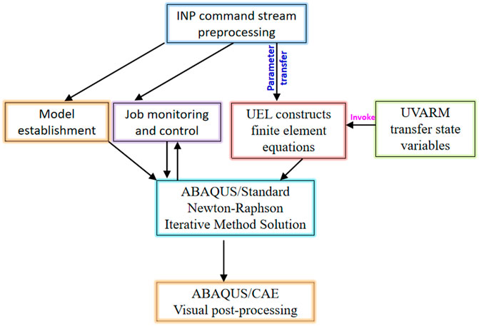
FIGURE 4. The programming framework of the multiscale finite element method based on ABAQUS software.
4 Larger scale direct shear test for determining the intrinsic length scale le
There are eight material property parameters in the multiscale coupled finite element method. The elastic modulus E, Poisson ratio, shear modulus G and bulk modulus K can be determined by the triaxial compression test of the soil matrix; The micro parameter
4.1 Test materials
The soil-rock mixture used in this paper is taken from the north of Guangzhou, China and mainly consists of silty clay and sandy mudstone. The soil-rock mixture was taken out from the excavation area first and fully turned over by a 20-t excavator to make the rock blocks in the soil-rock mixture evenly distributed in the soil matrix. The mixed soil and rock blocks were compacted in layers by a 14-t road roller with a compaction ratio of 92%. The compacted soil-rock mixture forms a test embankment. As shown in Figure 5, the large-scale direct shear test samples of soil-rock mixture were prepared inside the embankment. The physical and mechanical properties of soil-rock mixture were shown in Table 1. The maximum particle size of rock block is 50 mm, and the gradation curve of rock blocks is shown in Figure 6. For the water content, specific gravity and liquid plastic limit test of the soil-rock mixture, the tests were carried out after the solid particles with diameters greater than 2 mm were removed from the soil-rock mixture.
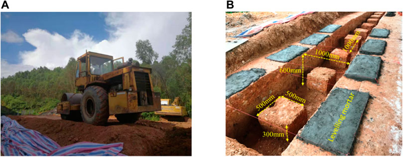
FIGURE 5. The test earth embankment and samples preparation. (A) Preparation of test soil-rock embankment, and (B) Preparation of large direct shear samples.

TABLE 1. The physical parameters of experiment materials.
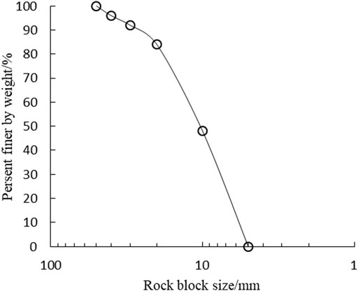
FIGURE 6. The gradation curve of rock blocks.
4.2 Test device
The large-scale direct shear test device was mainly composed of a shear frame (the inner dimension of the shear frame is 500 mm × 500 mm × 250 mm), reaction force supplying and loading application systems and stress and displacement acquisition system. The photographs of the equipment installation of the large-scale direct shear test were shown in Figure 7.
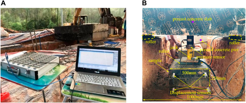
FIGURE 7. Photos of assembly of large-scale direct shear apparatus. (A) Reaction an data acquisition system, and (B) Loading of large direct shear samples.
4.3 Test scheme
The normal stress of each group of tests was 36, 72, 108 and 144kpa respectively, and each level of normal stress was loaded in three levels. The large-scale direct shear test scheme was shown in Table 2. The tests were conducted according to the Specification of soil test (GB/T50123-2019) Ministry of Water Resources of the People's Republic of China, 2019.

TABLE 2. Scheme of large-scale direct shear tests.
4.4 Test results and analysis
The shear stress-shear displacement curves of the samples were shown in Figure 8.
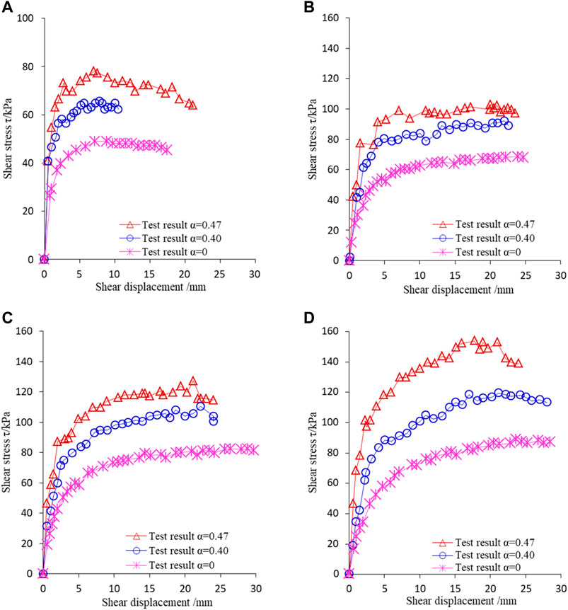
FIGURE 8. Curves of shear stress and shear displacement of soil-rock mixture samples. (A) Normal stress 36 kPa, (B) Normal stress 72 kPa, (C) Normal stress 108 kPa, and (D) Normal stress 144 kPa.
It can be seen from Figure 8 that the shear stress-shear displacement curves of pure matrix samples were relatively smooth; for the soil-rock mixture samples, the shear stress-shear displacement curve had serrated characteristics, and there was a discontinuous jump phenomenon of stress, and the overall mechanical response was strain hardening. Moreover, the shear strength of the soil-rock mixture samples increases with an increase in the content of the rock blocks under the all levels of normal stress conditions.
The above phenomenon that the shear strength and deformation characteristics of the soil-rock mixture changed with the change of the rock block content reflected the key influence of the rock blocks on the mechanical responses of soil-rock mixture.
5 Comparison between theoretical prediction and experimental results
It can be seen from Eqs 5, 9; Eq. 38 that the theoretical model (soil-rock cell model) of multiscale coupled shear strength of soil-rock mixture is embedded with the intrinsic scale
The matrix equivalent stress enhancement coefficient
The intrinsic length scale of soil-rock mixture is related to the equivalent stress enhancement coefficient
The strain gradient of the soil-rock mixture is related to the content and size of the rock blocks, which can be determined by Eq. 10.
The elastic modulus of the soil matrix is determined by conventional triaxial compression test of the pure matrix material, and the elastic modulus of the rock block is determined by the uniaxial compression test of the rock sample. The strain gradient and intrinsic length scale are determined by large scale direct shear test conducted on soil-rock mixture. For simplicity, Gm and ν0 are simply assumed according to previous studies (Zhang et al., 2015; Zhao et al., 2021). The specific calculation of the model parameters of the multiscale coupling soil-rock cell model of soil-rock mixture are shown in Table 3. Among them, the particle size of the rock blocks of soil-rock mixture is 5–50 mm. According to Eq. 5; Table 3, the relationship between shear stress and shear displacement of soil-rock mixture can be predicted. The comparison between theoretical results and experimental results is shown in Figure 9.
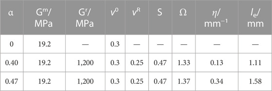
TABLE 3. The parameters of the mesomechanism based shear strength model of soil-rock mixture.
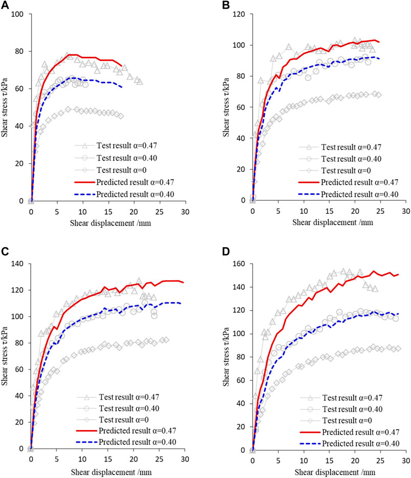
FIGURE 9. Comparisons of shear stress-shear displacement relationship between test and predicted results. (A) Normal stress 36 kPa, (B) Normal stress 72 kPa, (C) Normal stress 108 kPa, and (D) Normal stress 144 kPa.
It can be seen from Figure 9 that the multiscael soil-rock cell model of soil-rock mixture based on the meso physical mechanism can simulate and predict the shear stress-shear displacement relationship and the shear strength of soil-rock mixture. The relative error (
6 Multiscale finite element method for simulation of soil-rock mixture slope
Figure 10 shows the soil-rock mixture slope with a rock block content of 45%, with a slope height of 10 m and a slope ratio of 1:1. In the present work, the main physical and mechanical parameters of the soil-rock mixture are: elastic modulus E = 50MPa, Poisson’s ratio
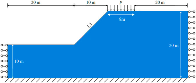
FIGURE 10. The model of the simulated soil-rock mixture slope.
The classical elastic-plastic finite element method and the multiscale coupled finite element method are respectively used to analyse the simulation of the stability of a soil-rock mixture slope. The finite element model is divided into four types of meshes, namely, 2,508, 2020, 1,660 and 1,286 elements. The displacement control method is adopted in loading process. The total vertical displacement loading is s = 0.5 m, the vertical uniformly distributed load on the top of the soil-rock mixture slope is p, and the width of the shear band of the soil-rock mixture slope is d0.
6.1 Parameter determination of the multiscale coupled finite element method
The parameters of the proposed multiscale finite element method are shown in Table 4. Herein, G is equal to Gm,

TABLE 4. Finite element method parameters of the proposed particle rotation theory.
6.2 Finite element simulation results of deformation characteristics of soil-rock mixture slope
6.2.1 Classical elastoplastic finite element simulation results of shear band width of soil-rock mixture slope
Figure 11 shows the simulation results of the shear band width of the soil-rock mixture slope by the classical elastic-plastic finite element method. The scale in the figure is the equivalent plastic strain of the soil-rock mixture slope, and the unit is %.
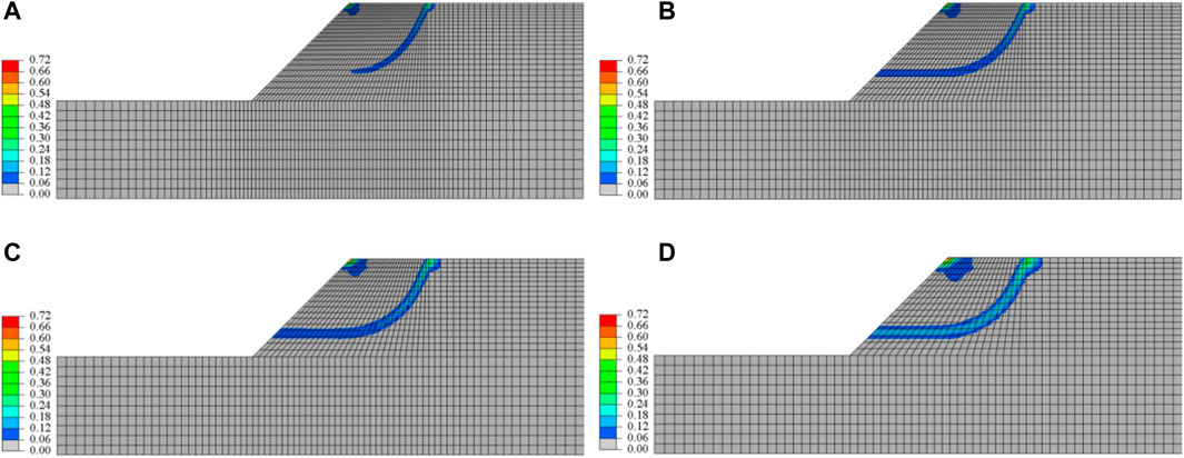
FIGURE 11. Color plot of equivalent plastic strain (in %) based on classical FEM. (A) Mesh 1, (B) Mesh 2, (C) Mesh 3, and (D) Mesh 4.
It can be seen from Figure 11 that the shear band width d0 of mesh one to mesh four is 0.62m, 0.76m, 0.98m and 1.31 m respectively, and the shear band width changes significantly with the change of the mesh size. The width of shear band predicted by mesh four is 111.3% higher than that of mesh 2, when the shear band of soil-rock mixture slope is completely interconnected. Therefore, the simulation results of the classical elastoplastic finite element method display significant pathological mesh-dependency.
Figure 12 shows the p∼s curve predicted by the classical elastic-plastic finite element method.
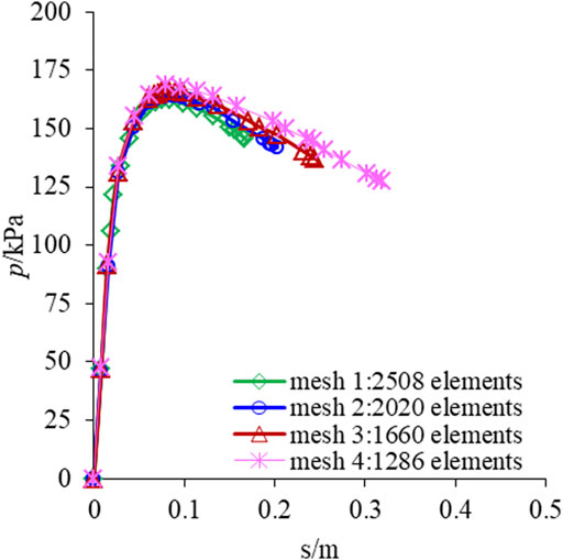
FIGURE 12. The p-s curves simulated by classical elastic-plastic finite element method.
Figure 12 shows that the denser is the mesh of the finite element model, the larger is the softening section of the p∼s curve, the stronger is the strain softening behaviour and the earlier is the calculation termination of the finite element program due to the difficulty in model solution. The calculation termination displacement s of mesh 1–4 are 0.168 m, 0.201 m, 0.244 m and 0.319 m, respectively. The difference of the calculation termination displacement caused by different mesh division is up to 89.9%, showing a significant pathological mesh-dependency.
6.2.2 Multiscale coupled finite element simulation results of shear band width of soil-rock mixture slope
Figure 13 shows the simulation results of the shear band width of the soil-rock mixture slope predicted by the multi-scale coupled finite element method. The scale in the figure is the equivalent plastic strain of the soil-rock mixture slope, and the unit is %.
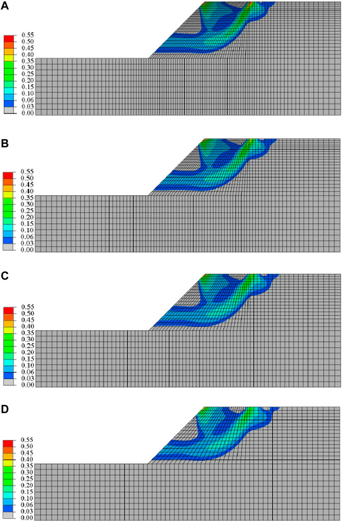
FIGURE 13. Color plot of equivalent plastic strain (in %) based on multiscale FEM (le = 0.1 mm). (A) Mesh 1, (B) Mesh 2, (C) Mesh 3, and (D) Mesh 4.
It can be seen from Figure 13 that the predicted results of the shear band width d0 of the soil-rock mixture slope by using the proposed multiscale coupled finite element program of mesh 1–4 are 3.32m, 3.43m, 3.48m and 3.51 m respectively. Especially, when the number of elements in mesh four is 48.7% less than that in mesh 1, the prediction result of shear band width is only increased by 5.7%, while under the same condition, the prediction result of classical elastic-plastic finite element method is increased by 111.3%. It can be seen that the multiscale coupled finite element method can effectively overcome the pathological mesh-dependency of numerical simulation prediction results.
Figure 14 shows the p∼s curves predicted by the multiscale coupled finite element method.
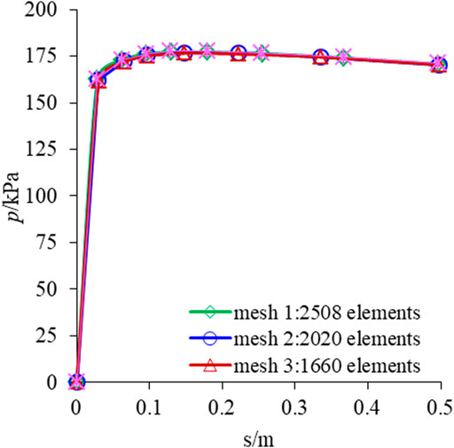
FIGURE 14. The p∼s curves simulated by multiscale finite element method.
It can be seen from Figure 14 that the p∼s curves predicted by the multiscale coupled finite element method completely coincide at the stage of uniform linearity, and also approximately coincide at the stage of plastic and softening deformation. The curves have only a slight difference with the reduction of the number of elements in the model, which is approximately the same as the shear band width predicted under different mesh densities in Figure 13A–D. Especially in the softening deformation stage, the multiscale coupled finite element method has no difficulty in solving that occurs in classical elastic-plastic finite element method. It can reproduce the entire nonlinear and softening deformation process of the soil-rock mixture slope. The displacement loading is s = 0.5 m, and the softening characteristics remain unchanged with the mesh changes. Therefore, the prediction results of the p∼s curves of the multiscale coupled finite element method depend on the physical and mechanical parameters of the soil-rock mixture and have nothing to do with the mesh density. It can simulate and predict the cross-scale evolution of the strain localization of the soil-rock mixture slope more realistically compared with that of the classical elastic-plastic finite element method.
For the multiscale coupled finite element method, the rotation of rock blocks induces the occurrence of stress concentration at the soil matrix around the soil-rock interface. When the stress concentration intensifies to a certain extent, plastic slip occurs at the interface first, and the plastic strain is constrained in the matrix between the rock blocks. The introduction of the rotational freedom of rock blocks can make the concentrated plastic strain transfer smoothly through the rotation of rock blocks. Moreover, the multiscale coupled finite element method introduces the intrinsic length scale
6.2.3 Simulation results of rock block rotation displacement of soil-rock mixture slope predicted by multi-scale coupled finite element method
Figure 15 shows the distribution of rotational displacement of rock blocks in the soil-rock mixture slope. The scale in the figure is the rotational displacement, and the unit is radian.
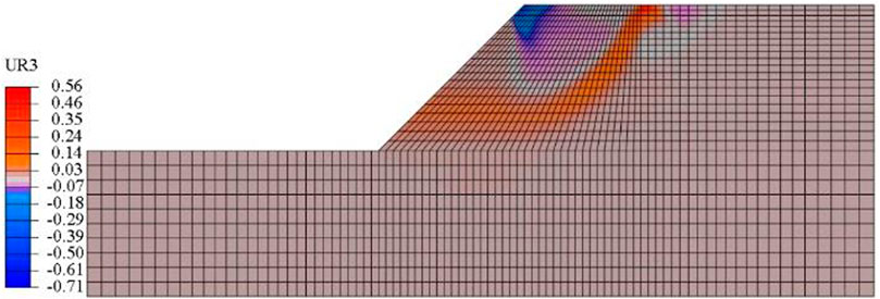
FIGURE 15. The rotation displacement simulated by multiscale FEM (mesh 2, le = 0.1 mm).
It can be seen from Figure 15 that the rotational displacement of rock blocks in the soil-rock mixture slope is mainly concentrated within the shear band, wherein the maximum rotational displacement of rock blocks is 40.7°, and the rotational displacement of particles outside the shear band is about 0°. The rotational displacement of the rock blocks in the shear band of the soil-rock mixture slope changes the meso-structures of the soil-rock mixture, which produces unrecoverable plastic deformation (Ren and Zhao 2021). In this process, the directional alignment of the rock blocks caused by their rotational displacement destroys the occlusion effect between rock blocks, and weakens the ability of rock blocks to transfer shear deformation to the surrounding soil matrix, thus leading to the plastic deformation being restrained and the occurrence of plastic strain localization. The plastic strain localization gradually evolves into a shear band, and the gradual penetration of the shear band causes the sliding failure of the soil-rock mixture slope. Therefore, the plastic strain concentration of the soil-rock mixture caused by the rotation and directional arrangement of the rock blocks in the soil-rock mixture slope is the most critical factor for the formation and development of the shear band of the soil-rock mixture slope.
7 Conclusion
According to the physical and mechanical effects generated by the interaction between soil matrix and rock blocks in the soil-rock mixture, the multiscale coupled elastic-plastic constitutive relationship of the soil-rock mixture is derived and the corresponding multiscale coupled finite element procedure is independently programmed. The cross-scale deformation characteristics of the soil-rock mixture slope are successfully simulated and predicted by the proposed multiscale finite element method. The main conclusions are as follows:
(1) The multiscale coupled constitutive relationship established based on the micro motion characteristics of soil-rock mixture is embedded with the rotational freedom of rock blocks, which can effectively simulate and predict the cross-scale shear strength of the soil-rock mixture.
(2) The multiscale finite element program can quantitatively simulate the rotational displacement of the element and effectively realize the cross-scale coupling relationship between the micro rotation of the rock blocks and the macro mechanical response of the soil-rock mixture. Moreover, the intrinsic length scale that regularizes the stiffness matrix of the finite element method is embedded in the multiscale finite element program, which can overcome the pathological mesh-dependency of the classical finite element method, and thus objectively and completely describe the progressive deformation of soil-rock mixture slope from particle rotation at the microscale to the sliding failure of the soil-rock mixture at the macroscale.
(3) The maximum rotational displacement of rock blocks inside the soil-rock mixture slope is 40.7°, mainly concentrated in the shear band, and the rotational displacement of rock blocks outside the shear zone is about 0°. The plastic strain concentration of the soil-rock mixture caused by the rotation and directional arrangement of the rock blocks in the soil-rock mixture is the most critical factor for the formation and development of the shear band of the soil-rock mixture slope.
Finally, it is noted that the proposed soil-rock cell element model is a preliminary investigation of the derivation of multiscale coupling theoretical model of the S-RM, only three groups of the in situ large-scale direct shear tests were carried out to calculate the parameters of the proposed multiscale soil-rock cell element model and evaluate the feasibility of the proposed model. Meanwhile, the shape and breakage of rock blocks have not been considered in the present work. Therefore, specific and systematic experimental studies and theoretical enhancements are expected to improve and validate the proposed multiscale FEM model in the future work.
Data availability statement
The raw data supporting the conclusion of this article will be made available by the authors, without undue reservation.
Author contributions
JL: Conceptualization, Methodology, Software, Test. DF: Data curation, Writing—Original draft preparation Writing—Reviewing and Editing.
Acknowledgments
We are grateful to the National Natural Science Foundation of China (grant number 52078142) for financial support.
Conflict of interest
Author JL was employed by the Investment and Development Co., Ltd.
The remaining authors declare that the research was conducted in the absence of any commercial or financial relationships that could be construed as a potential conflict of interest.
Publisher’s note
All claims expressed in this article are solely those of the authors and do not necessarily represent those of their affiliated organizations, or those of the publisher, the editors and the reviewers. Any product that may be evaluated in this article, or claim that may be made by its manufacturer, is not guaranteed or endorsed by the publisher.
References
Arriaga, M., Mcauliffe, C., and Waisman, H. (2015). Onset of shear band localization by a local generalized eigenvalue analysis. Comput. Methods Appl. Mech. Eng. 289, 179–208. doi:10.1016/j.cma.2015.02.010
Borst, R. D. (1991). Simulation of strain localization: A reappraisal of the cosserat continuum. Eng. Comput. 8 (4), 317–332. doi:10.1108/eb023842
Broumand, P., and Khoei, A. R. (2013). The extended finite element method for large deformation ductile fracture problems with a non-local damage-plasticity model. Eng. Fract. Mech. 112, 97–125. doi:10.1016/j.engfracmech.2013.10.002
Bubeck, A., Walker, R., Healy, D., Dobbs, M., and Holwell, D. (2017). Pore geometry as a control on rock strength. Earth Planet. Sci. Lett. 457, 38–48. doi:10.1016/j.epsl.2016.09.050
Cai, X. Y., Sang, D., Yuchi, C. X., Cui, W., Zhang, C., Du, C. F., et al. (2020). Using finite element analysis to determine effects of the motion loading method on facet joint forces after cervical disc degeneration. Comput. Biol. Med. 116, 103519. doi:10.1016/j.compbiomed.2019.103519
Chang, J. F., Wang, W., Niu, Q. H., Wen, L., and Yuan, W. (2021). Effect of fabric anisotropy on bifurcation and shear band evolution in granular geomaterials. KSCE J. Civ. Eng. 25 (8), 2893–2910. doi:10.1007/s12205-021-2164-5
Collinswilliams, C. (2015). The field monitoring and finite element analysis of axial force of a deep foundation pit's reinforced concrete inner-supporting. Int. Archives Allergy & Immunol. 20 (1), 38–59. doi:10.4028/www.scientific.net/AMM.775.237
Du, X., Zhang, P., and Jin, L. (2017). A mesoscopic equivalent analysis method for the study on macromechanical properties of soil-rock mixture. Eng. Mech. 34 (10), 51–59. doi:10.6052/j.issn.1000-4750.2016.03.0181
Eshelby, J. D. (1957). The determination of the elastic field of an ellipsoidal inclusion, and related problems. Proc. R. Soc. Lond. Ser. A. Math. Phys. Sci. 241 (1226), 376–396. doi:10.1098/rspa.1957.0133
Fang, Y. G., Feng, D. L., Ma, W. X., Gu, R. G., and He, Z. W. (2013). Theoretical and experimental study on size effect of soil strength. Chin. J. Rock Mech. Eng. 32 (11), 2359–2367.
Fang, Y. G., and Li, B. (2016). Multiscale problems and analysis of soil mechanics. Mech. Mater. 103, 55–67. doi:10.1016/j.mechmat.2016.09.003
Fang, Y. G. (2014). Shear test and physical mechanism analysis on size effect of granular media. Acta Phys. Sin. 63 (3), 034502. doi:10.7498/aps.63.034502
Feng, D. L., and Fang, Y. G. (2016). Theoretical analysis and experimental research on multiscale mechanical properties of soil. Int. J. Geomechanics 04015094, 1–12. doi:10.1061/(asce)gm.1943-5622.0000573
Feng, D. L., and Fang, Y. G. (2015a). Theoretical and experimental research on particle size effect of direct shear mechanical properties of soil. Chin. J. Rock Mech. Eng. 34 (S2), 4307–4319. doi:10.13722/j.cnki.jrme.2014.0742
Feng, D. L., and Fang, Y. G. (2015b). Theoretical and experimental study of particle size effect of direct shear mechanical properties of soil. Rock Soil Mech. 36 (S1), 209–214. doi:10.16285/j.rsm.2015.S2.010
Feng, D. L., and Fang, Y. G. (2015c). Theoretical and experimental study on multi-scale mechanical properties of soil. Soil Mech. Found. Eng. 52 (4), 189–197. doi:10.1007/s11204-015-9327-7
Gao, H., Huang, Y., Nix, W., and Hutchinson, J. W. (1999). Mechanism-based strain gradient plasticity-I. Theory. J. Mech. Phys. Solids 47 (6), 1239–1263. doi:10.1016/s0022-5096(98)00103-3
Goodman, R. E., Taylor, R. L., and Brekke, T. L. (1968). A model for the mechanics of jointed rock. J. Soil Mech. Found. Div. 94 (3), 637–659. doi:10.1061/jsfeaq.0001133
Guo, N., Yang, Z., Yuan, W., and Zhao, J. (2021). A coupled SPFEM/DEM approach for multiscale modeling of large-deformation geomechanical problems. Int. J. Numer. Anal. Methods Geomechanics 45, 648–667. doi:10.1002/nag.3175
Guo, N., and Zhao, J. (2015). The interplay between anisotropy and strain localisation in granular soils: A multiscale insight. Geotechnique 65 (8), 642–656. doi:10.1680/geot.14.p.184
Hill, R. (1963). Elastic properties of reinforced solids: Some theoretical principles. J. Mech. Phys. Solids 11 (5), 357–372. doi:10.1016/0022-5096(63)90036-x
Hu, M., Xu, G., and Hu, S. B. (2013). Study of equivalent elastic modulus of sand gravel soil with Eshelby tensor and Mori-Tanaka equivalent method. Rock Soil Mech. 34 (5), 1437–1442+1448.
Huang, W-x., Pu, J-l., and Chen, Y-j (1981). Hardening rule and yield function for soils[J]. Chin. J. Geotech. Eng. 3 (3), 19–26.
Li, C. S., Zhang, D., Du, S. S., and Shi, B. (2016). Computed tomography based numerical simulation for triaxial test of soil–rock mixture. Comput. Geotechnics 73, 179–188. doi:10.1016/j.compgeo.2015.12.005
Li, X., and Wan, K. (2011). A bridging scale method for granular materials with discrete particle assembly – cosserat continuum modeling. Comput. Geotechnics 38 (8), 1052–1068. doi:10.1016/j.compgeo.2011.07.001
Liang, W., and Zhao, J. (2019). Multiscale modeling of large deformation in geomechanics. Int. J. Numer. Anal. Methods Geomechanics 43 (5), 1080–1114. doi:10.1002/nag.2921
Ling, D., and Ye, M. (2005). Manifold element method for biot's plane consolidation analysis. Chin. J. Comput. Mech. 22 (3), 274–280. doi:10.3969/j.issn.1007-4708.2005.03.004
Liu, S. Y., Shao, L. T., and Li, H. J. (2015). Slope stability analysis using the limit equilibrium method and two finite element methods. Comput. Geotechnics 63, 291–298. doi:10.1016/j.compgeo.2014.10.008
Mikkelsen, L., Legarth, B., Herrmann, L., Christensen, M. M., and Niordson, C. F. (2022). A special finite element method applied to off-axis tunnel cracking in laminates. Eng. Fract. Mech. 268, 108387. doi:10.1016/j.engfracmech.2022.108387
Mindlin, R. D. (1963). Influence of couple-stresses on stress concentrations. Exp. Mech. 3 (1), 1–7. doi:10.1007/bf02327219
Ministry of Water Resources of the People’s Republic of China (2019). GB/T50123-2019 Specification of soil test. Beijing: China Architecture and Building Press.
Mori, T., and Tanaka, K. (1973). Average stress in matrix and average elastic energy of materials with misfitting inclusions. Acta metall. 21 (5), 571–574. doi:10.1016/0001-6160(73)90064-3
Ren, M., and Zhao, G. (2021). Prediction of compressive strength of the welded matrix-rock mixture by meso-inclusion theory. Int. J. Rock Mech. Min. Sci. 139 (2), 104612. doi:10.1016/j.ijrmms.2021.104612
Soltani, M., and Maekawa, K. (2015). Numerical simulation of progressive shear localization and scale effect in cohesionless soil media. Int. J. Non Linear Mech. 69, 1–13. doi:10.1016/j.ijnonlinmec.2014.10.014
Strouboulis, T., Copps, K., and Babuska, I. (2001). The generalized finite element method. Comput. Methods Appl. Mech. Eng. 190 (32-33), 4081–4193. doi:10.1016/s0045-7825(01)00188-8
Tang, H., Dong, Y., Wang, T., and Dong, Y. F. (2018). Simulation of strain localization with discrete element-cosserat continuum finite element two scale method for granular materials. J. Mech. Phys. Solids 122, 450–471. doi:10.1016/j.jmps.2018.09.029
Toupin, R. A. (1962). Elastic materials with couple-stresses. Archive Ration. Mech. Analysis 11 (1), 385–414. doi:10.1007/bf00253945
Wang, S., Li, Y., Gao, X., Xue, Q., Zhang, P., and Wu, Z. (2020). Influence of volumetric block proportion on mechanical properties of virtual soil-rock mixtures. Eng. Geol. 278 (1), 105850. doi:10.1016/j.enggeo.2020.105850
Wang, Y., Li, C. H., and Hu, Y. Z. (2018). Use of X-ray computed tomography to investigate the effect of rock blocks on meso-structural changes in soil-rock mixture under triaxial deformation. Constr. Build. Mater. 164, 386–399. doi:10.1016/j.conbuildmat.2017.12.173
Weng, G. J. (1984). Some elastic properties of reinforced solids, with special reference to isotropic ones containing spherical inclusions. Int. J. Eng. Sci. 22 (7), 845–856. doi:10.1016/0020-7225(84)90033-8
Xu, W. J., Xu, Q., and Hu, R. L. (2011). Study on the shear strength of soil–rock mixture by large scale direct shear test. Int. J. Rock Mech. Min. Sci. 48 (8), 1235–1247. doi:10.1016/j.ijrmms.2011.09.018
Xu, W. J., Yue, Z. Q., and Hu, R. L. (2008). Study on the meso-structure and meso-mechanical characteristics of the soil-rock mixture using digital image processing based finite element method. Int. J. Rock Mech. Min. Sci. 45 (5), 749–762. doi:10.1016/j.ijrmms.2007.09.003
Yang, Z., Zhao, Y., Hu, Y., Li, S., Lei, X., and Li, X. (2021). Effect of the strength of rock blocks on the shear characteristics of soil-rock mixtures. Chin. J. Rock Mech. Eng. 40 (4), 814–827. doi:10.13722/j.cnki.jrme.2020.0488
Zhang, H., Xu, W., and Yu, Y. (2016). Triaxial testsofsoil–rock mixtures with different rock block distributions. Soils Found. 56 (1), 44–56. doi:10.1016/j.sandf.2016.01.004
Zhang, S., Tang, H., Zhan, H., Lei, G., and Cheng, H. (2015). Investigation of scale effect of numerical unconfined compression strengths of virtual colluvial–deluvial soil–rockmixture. Int. J. Rock Mech. Min. Sci. 77, 208–219. doi:10.1016/j.ijrmms.2015.04.012
Zhao, L., Huang, D. A., Zhang, S. A., Xiao, C., and Yibo, L. (2021). A new method for constructing finite difference model of soil-rock mixture slope and its stability analysis. Int. J. Rock Mech. Min. Sci. 138, 104605. doi:10.1016/j.ijrmms.2020.104605
Zhao, Z., and Zhou, X. P. (2020). Establishment of numerical cracking constitutive models using 3D reconstruction and X-ray CT images of geomaterials. Int. J. Mech. Sci. 183 (22), 105814. doi:10.1016/j.ijmecsci.2020.105814
Keywords: soil mechanics, soil-rock mixture, finite element program, multiscale, rotation displacement
Citation: Liu J and Feng D (2023) A multiscale finite element method for soil-rock mixture. Front. Mater. 10:1116544. doi: 10.3389/fmats.2023.1116544
Received: 05 December 2022; Accepted: 20 February 2023;
Published: 06 March 2023.
Edited by:
Jialai Wang, University of Alabama, United StatesReviewed by:
Guoping Zhang, University of Massachusetts Amherst, United StatesDunja Peric, Kansas State University, United States
Copyright © 2023 Liu and Feng. This is an open-access article distributed under the terms of the Creative Commons Attribution License (CC BY). The use, distribution or reproduction in other forums is permitted, provided the original author(s) and the copyright owner(s) are credited and that the original publication in this journal is cited, in accordance with accepted academic practice. No use, distribution or reproduction is permitted which does not comply with these terms.
*Correspondence: Deluan Feng, d29sZmx1YW5AMTI2LmNvbQ==