 Mugunth Vishali1*
 Alireza Bahrami2*Kachabeswara Srinivasan Satyanarayanan1Varatharajan Thirumurugan1Murugan Prakash1
- 1Department of Civil Engineering, SRM Institute of Science and Technology, Kattankulathur, India
- 2Department of Building Engineering, Energy Systems and Sustainability Science, Faculty of Engineering and Sustainable Development, University of Gävle, Gävle, Sweden
Infilled frames are generally formed by the composite interaction between the frame and the infilled wall used for functional purposes. The composite interaction increases the in-plane lateral stiffness of the frame, which is considered an advantage. However, the interaction also alters the ductile mode of failure to the brittle mode along with the increased base shear owing to its higher stiffness compared with the bare frame. A detailed and comprehensive study of the literature revealed that many of research works have been done on rectangular and square frames, and studies on trapezoidal infilled frames are scarce. In this article, we studied different configurations of reinforced concrete frame structures known as trapezoidal frames, which have higher stiffness than rectangular frames. A trapezoidal frame is used for industrial buildings, and its behavior under a lateral load has already been established for a bare frame. However, the interaction and behavior of the infilled frame were investigated in this research. The behavior of a trapezoidal single-story frame was examined under both lateral loading and various interface materials. One of the most frequently suggested methods for infilled-frame analysis is the equivalent diagonal strut. Effective strut width design recommendations are available for rectangular and square frames but not for trapezoidal frames for macro modeling. Hence, to make the design easier, an effective diagonal width was developed for different interface materials with respect to the relative stiffness of various frame cross-sections, and further validation was conducted with a framework of ideology from biomimicry using the nature of a one-sixth scale model. The effective strut width for the trapezoidal infilled frame varied between d/8 and d/9 for the cement mortar and cork interfaces, where d is the diagonal length of the frame.
1 Introduction
According to recent data, earthquakes are severe natural hazards worldwide, and the numerous deaths from earthquakes worldwide accounted for 55% of deaths from natural disasters in the 20th century (Cao et al., 2020). The effective reduction of the impact of earthquakes on structures has become a key topic in modern seismic research. There has been a surge in interest for the force-isolation and energy–dissipation methods in recent times (FEMA, 2000), in inclusion to the conventional strengthening of building types such as widening section areas, developing different configurations, and introducing novel materials (Zhao and Zhang, 2007; Zhang et al., 2019; De Lorenzis and Teng, 2007). Recently, buildings have tended to use infilled frame concepts because these types of structural systems resist more lateral forces such as seismic and wind forces. Infilled frames are planar composite structural systems that increase the lateral stiffness of planar frames (Muthu Kumar and Satyanarayanan, 2018). Masonry-infilled reinforced concrete (RC) frames are the most popular type of multistory structures in developing nations, including those in earthquake-prone areas. In RC frame construction, masonry infilled walls are primarily utilized to boost the initial stiffness and strength. Brick masonry infill is often the preferred material for buildings because of its familiarity and easy availability. Infilled panels made of masonry are commonly used in surrounding areas, such as walls around stairs, interior walls, and exterior walls (Muthu Kumar et al., 2017; Muthu Kumar et al., 2016; Senthil et al., 2018). The inclusion of an infill in a frame is widely acknowledged to provide significant improvements (Motovali Emami et al., 2017). This is economically significant for tall buildings with strong lateral loading. One of the most frequently suggested methods for analyzing infilled frames is the equivalent diagonal strut (Smith, 1967). In accordance with an earlier study, an equivalent diagonal strut replaced the infilled wall. Smith et al. (1970) and Holmes et al. (1962) developed an equivalent strut concept for a rectangular infilled frame with respect to the relative stiffness of λh. The effects of using wall panels as a composite with frames subjected to horizontal loading that tends to cause side sway were further examined for stiffening and strengthening (Pohoryles and Bournas, 2020). Liauw (1972) evaluated rectangular infilled frames with and without openings. A study based on a rectangular infilled unified-oriented micro-modeling approach for RC infilled frames was developed and assessed (Sandoli et al., 2020). The development of the strut-and-tie model was done to predict the peak shear strength of squat shear walls with and without boundary elements (Chetchotisak et al., 2021). Srechai et al. (2022) presented a novel numerical modeling of infilled RC frames. The peak response of the squat shear wall model (strut tie) was developed, and a prediction analysis was performed with and without boundary features.
Although there have been intensive studies on rectangular- and square-shaped infilled frames worldwide, and equivalent diagonal strut methods have been derived for these structures, there are limited works on trapezoidal frames under lateral loading. Figure 1 depicts an example of building with the trapezoidal shape.

FIGURE 1. Trapezoidal type of building (Srishti, 2022).
For the lateral force resistance, the trapezoidal type of frame is sufficiently good when compared with the normal rectangular and square frames, and provides good aesthetics to the building (Vishali et al., 2021). An experimental investigation employing the ideology of biomimicry using nature and a numerical technique is presented in this article, and the effective diagonal width for the trapezoidal frame was investigated. In addition, the effective diagonal widths for different interface materials with respect to the relative stiffness of various frame cross-sections are compared and discussed. The overall methodology of this study is illustrated in Figure 2.
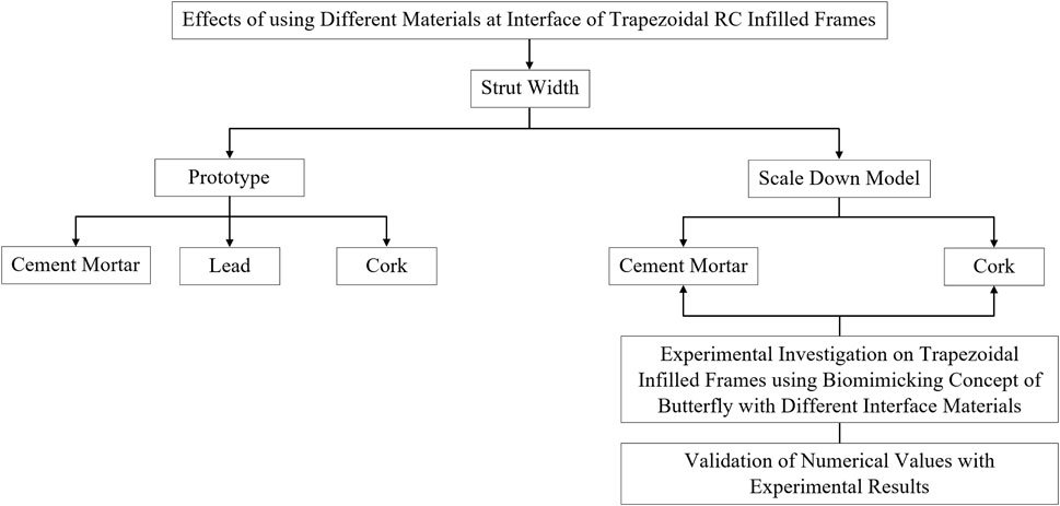
FIGURE 2. Methodology of study.
1.1 Research significance
• Numerous studies have examined the behavior and performance of infilled frames with rectangular shapes, which are infilled frames with straight columns; however, studies on infilled frames with inclined columns have been limited.
• The influence of different interface materials on infilled frames with inclined columns is limited. Therefore, detailed studies related to different interface materials needed to be conducted.
• Different sizes and positions of openings in the infill for infilled frames with inclined columns are scarce. Hence, studies related to the different sizes and positions of openings in infilled panels needed to be performed in detail.
• The equivalent diagonal strut width was developed only for the rectangular infilled frames. Consequently, the development of a strut width equation for trapezoidal frames needed to be studied and verified.
1.2 Objectives
• To develop and verify the strut width equation for trapezoidal infilled frames with different interface materials for use in the equivalent frame analysis.
• To perform experimental investigation on using different interface materials in trapezoidal infilled frames biomimicked from butterfly wings.
• To evaluate the elastic behavior of trapezoidal frames using different interface materials (such as cement, cork, and lead) under static monotonic lateral loading.
1.3 Scope
• A 2-dimensional (2D) RC trapezoidal frame with different interfaces was studied using the finite element software ABAQUS.
• The applied load was an in-plane static monotonic lateral loading.
• The M30 grade of concrete and Fe415 grade of steel as reinforcement were used for the RC structure of the study.
• The different interface materials such as cork and conventional interface material, cement mortar, were utilized for comparison.
• A comparison of the elastic behavior of a 2D trapezoidal infilled frame was done having different interface characteristics under varying parameters, such as the displacement and stiffness.
2 Analytical investigation
2.1 Modeling and analysis
A simulation of the 2D RC trapezoidal frame as a solid element was conducted using the finite element software ABAQUS. The RC single-bay, single-story frame was modeled with the elements of the previous research performed by Muthu Kumar et al. (2015). The RC section was modeled as a 3-dimensional (3D) deformable solid element, and the reinforcements were modeled as wire elements. The interface element, which is a 3D element with six degrees of freedom at each node, has the properties of an interface material connected to the frame and infill. The masonry was modeled as a meso-element with the average properties of brick masonry based on the previous research. While the RC frame was given fixed support conditions, the interface material was positioned between the infill and the RC frame. To maintain uniform material properties, such as the density, modulus of elasticity, and Poisson’s ratio, as listed in Table 1, concrete of M30 grade and steel reinforcement of Fe415 grade were used in all the cases. An initial prototype frame was created by incorporating the dimensions and reinforcement specifications provided in Table 2. The angle of the column inclination for the trapezoidal frame was set to 60°. Figure 3 shows the finite element prototype models of the trapezoidal bare and infilled frames. Initially, three cross-sections of the frame were investigated analytically, i.e., 300 mm × 300 mm, 300 mm × 400 mm, and 300 mm × 500 mm. It was found from the investigation that there was no significant improvement in the stiffness by the change of the cross-sections. Therefore, the cross-section of 300 mm × 400 mm was used to scale down for the experiment. The scaled-down model was adopted as a one-sixth ratio of the prototype frame. The details of the scaled-down model are listed in Table 2.
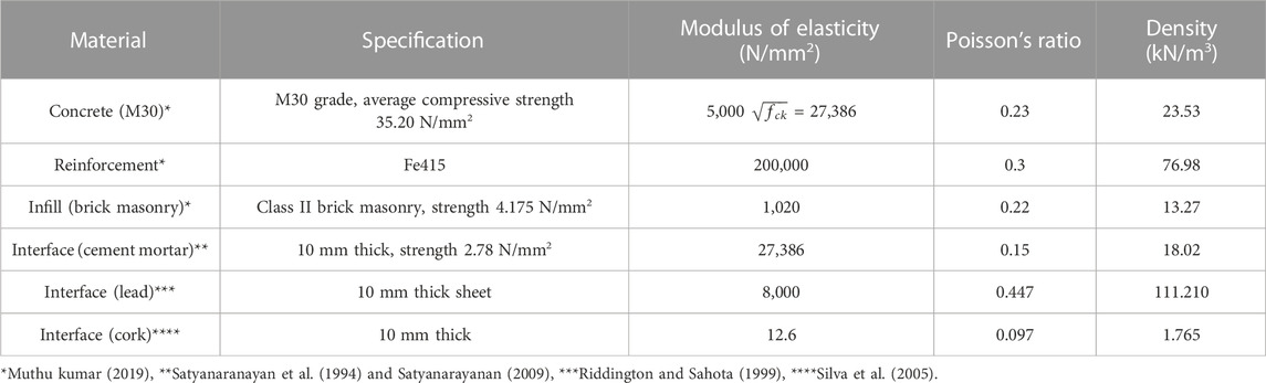
TABLE 1. Properties of used materials.
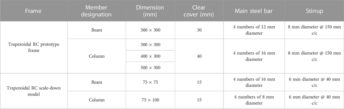
TABLE 2. Dimensions and reinforcements of 2D trapezoidal RC prototype frame and scale-down model.
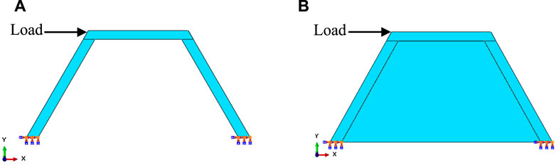
FIGURE 3. Finite element prototype models; (A) trapezoidal bare frame, (B) trapezoidal infilled frame.
2.2 Meshing and discretization
To determine the consistent stiffness required for the solid element, a convergence study of the infill element was performed during the development of the finite element model for the infilled frame. In an object-based model, discretization is the process by which a material domain is transformed into an analytical model that can be used for the analysis (Muthu Kumar, 2019).
In the finite element analysis, the element was discretized to achieve the convergence of the results. A mesh convergence analysis was conducted on the infill with element sizes ranging from 10 mm × 10 mm – 50 mm × 50 mm. For the analysis, a 1 kN load was applied to the infill. A mesh sensitivity analysis was done to assess the impact on the frame displacement and infill strain. Monotonic convergence was also examined in terms of the displacement. As a result, only the displacement was considered in the mesh sensitivity analyses. From the analysis of different mesh sizes, it was found that for a 50 mm × 50 mm mesh size, the frame displacement was constant. A mesh size of 50 mm was chosen for the entire element in the analytical work, based on the findings of the mesh convergence study.
2.3 Loading and interaction
The loading phase plays a crucial role in interpreting the results, in which a static monotonic horizontal load of 10 kN was applied at the top left beam-column intersection. An interaction between the reinforcement and RC frame was modeled as an embedded region with discrete connection constraints for the interface material and wall of the filling, while also providing representational control over the surface-surface interaction.
3 Theoretical investigation
3.1 Investigation of strut width for trapezoidal infilled frame
The typical strut width of a trapezoidal frame can be roughly divided into three stages. In the first stage, the stiffness of the infilled frame was estimated, and the pressure intensity within the infill was determined through an analytical investigation. The second stage was an approximate method for determining the reaction force in the equivalent frame so that the stiffness values of the plain frame were equal to those of the infilled frame. The final stage followed the kinematic equivalence method utilizing Eq. 1 to derive the strut width of the infilled frame with various column cross-sections and different interface materials.
where
The derived strut widths for the prototype frame and scaled-down model of the trapezoidal infilled frame are presented in Table 3.
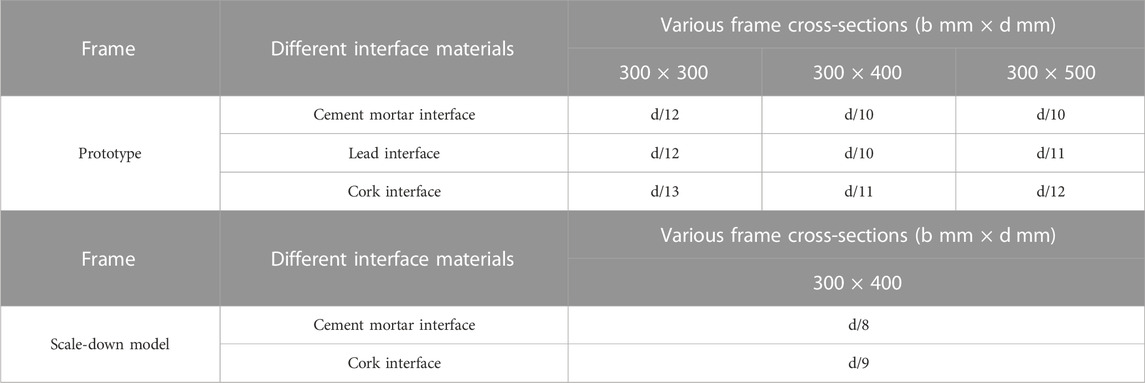
TABLE 3. Theoretical values of w for prototype frame and scale-down model.
Using a non-dimensional parameter λh (relative stiffness of the infill), Eq. 2 (Smith et al., 1970), a relationship may be established between λh and w, representing the relative stiffness and the strut width of the frame, respectively. The equivalent strut width as a function of λh for the prototype frame with various column cross-sections and different interface materials is displayed in Figure 4A. Similarly, the equivalent strut width as a function of λh for the scale-down model is demonstrated in Figure 4B.
where,
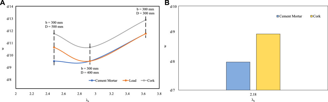
FIGURE 4. Equivalent strut width for function of λh; (A) prototype, (B) scale-down model.
According to Smith et al. (1970), experiments have revealed that the diagonal stiffness and strength of an infilled panel depend on the applied load and the relative properties of the frame and infill. They also depend on the length of the contact. The length of the contact α was determined using Eq. 3, which is calculated in terms of the relative stiffness of the frame. The relationship between α/h and λh has indicated to exhibit a remarkably similar trend to that of the equation’s curve.
Therefore, considering the contact length of the column, the graph was plotted as a function of λh, as depicted in Figure 5.

FIGURE 5. Contact length as function of λh.
4 Experimental investigation
4.1 Experimental setup
To consider the numerical results based on the one-sixth scale-down model under lateral loading, a trapezoidal-shaped infill was designed and filled with cut bricks, as shown in Figure 6A. For infilling, cut bricks from scaled earth bricks with the dimensions of 220 mm × 100 mm × 70 mm were utilized. The dimensions of these bricks were 100 mm, 65 mm, and 70 mm. To investigate the strut width pattern and load-carrying capacity under vertical loading conditions, both inclined bed joint (IBJ) and normal bed joint (NBJ) were tested, as illustrated in Figures 6B–E. Generally, the values of the masonry properties were employed based on the horizontal load testing. The bed joint would be loaded normally, whereas for this specific case, depending on the stress flow, the specimen was taken and tested as an IBJ. This case is applicable to an infilled frame where the stresses are inclined to the bed joint. Masonry has autotrophy with respect to inclination. The plane of weakness is the bed joint; however, in practice, the masonry properties are determined based on loading perpendicular to the bed joint and then used. In this study, we attempted to determine the effect of considering the stress direction with respect to the direction. The specimens consisted of cut bricks, and both sides were covered with cement mortar paste. For this purpose, cement mortar with cement:sand ratio of 1:4 and water/cement ratio of 0.8 was utilized. The compressive strength of the cut bricks was 9.59 MPa, which was obtained from the compression test using a digital compression testing machine with the capacity of 1,000 kN. Two different sets of specimens, as IBJ and NBJ, were used with different shapes and dimensions for the current research work. The lengths (L) of IBJ and NBJ were 85 mm and 100 mm, respectively. The widths (w) of both specimens were 130 mm and 80 mm, respectively. The dimensions of IBJ and NBJ were 100 mm × 80 mm × 400 mm and 85 mm × 130 mm × 780 mm, respectively. The modulus of elasticity values of both specimens were achieved.
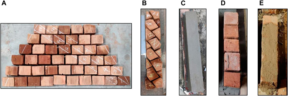
FIGURE 6. (A) Cut bricks filled in trapezoidal infill, (B and C) Preparation of IBJ, (D and E) Preparation of NBJ.
4.2 Experimental results
In order to obtain the strength and modulus of elasticity for both IBJ and NBJ specimens subjected to vertical loading, the strain values were calculated for both specimens. The strain values were calculated using demec pins that were measured on both sides of the specimens. Figures 7A,B illustrate the test setup for both IBJ and NBJ.

FIGURE 7. Experimental investigation; (A) experimental setup of IBJ, (B) experimental setup of NBJ, (C) failure of IBJ, (D) failure of NBJ.
Based on the experiments, the strengths of IBJ and NBJ were measured and are listed in Table 4. The strength of IBJ was smaller than that of NBJ. This was because shear stresses were absent over IBJ. The failures of IBJ and NBJ are displayed in Figures 7C,D. In addition to the modulus of elasticity, the stress-strain curves for both IBJ and NBJ are indicated in Figure 8A. It was found that NBJ had higher modulus of elasticity (1063 N/mm2) than IBJ (840 N/mm2). The reason behind this was because the stresses were directly normal and produced more shear stress because the load was perpendicular to the bed joint. Therefore, this direction appeared to be the strongest loading direction for the mortar joint.

TABLE 4. Comparison of strengths.
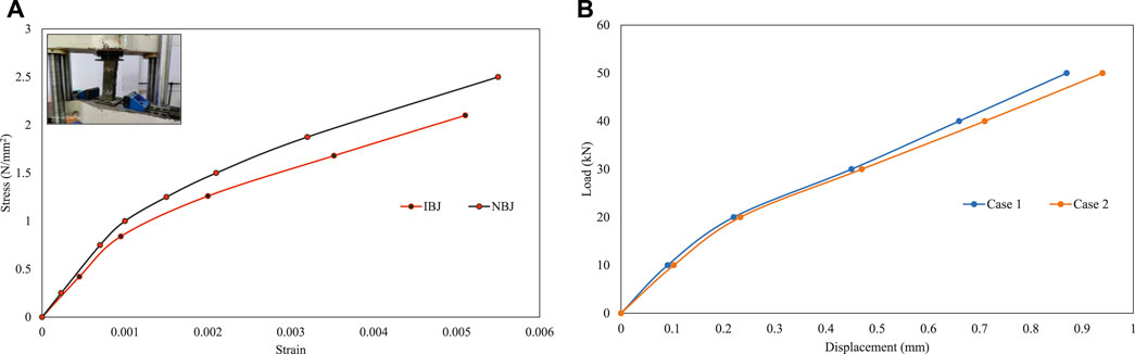
FIGURE 8. Experimental results; (A) stress-strain curves, (B) load-displacement curves.
4.3 Numerical models validated with experimental results
The numerical models were validated based on experimental results. The values of modulus of elasticity obtained from the stress-strain curves in the experimental results were validated by the numerical models using ABAQUS. The infill was analyzed using the modulus of elasticity of IBJ and compared with the trapezoidal bare frame. However, the trapezoidal bare frame should have a diagonal strut width reaction force of the cement mortar interface applied to the equivalent frame. Table 5 presents the displacement values for the trapezoidal bare and filled frames. Figure 8B demonstrates the load–displacement curves for both cases (Case 1 and Case 2).

TABLE 5. Comparison of displacement values.
The above-mentioned results indicated that the deformation patterns and displacements of the finite element models were similar to those of the experimental results, demonstrating that the numerical model developed in this study was sufficiently accurate for simulating trapezoidal frames with various interface materials subjected to lateral loading.
5 Investigation of strut width with idea of using biomimicry of butterfly wings
In these numerical and experimental approaches, the geometry of the frame was formed based on biomimicry of butterfly wings. Naturally, the geometry of butterfly wings gives good lateral flexibility, whereas in the current research work, the geometry was reversed so that the resulted shape would have higher stiffness in the lateral direction. Thus, it can be concluded that inverting the shape of butterfly wings provides good stability for the structural action. The ratios of the wing dimensions are depicted in Figure 9. Therefore, the idea of biomimicry was utilized here to test two frames simultaneously with different interface materials. Biomimicry is a novel scientific approach that explores nature as a source of inspiration and models to address human challenges by imitating design and processes (Dash, 2018). The primary aim of this type of frame design is to reduce the number of used materials. It was found that testing of two specimens with a single foundation was more efficient than that of two separate specimens with separate foundations. By testing the specimens in this way, the use of materials, cost, weight, and time showed significant changes, as illustrated in Table 6.
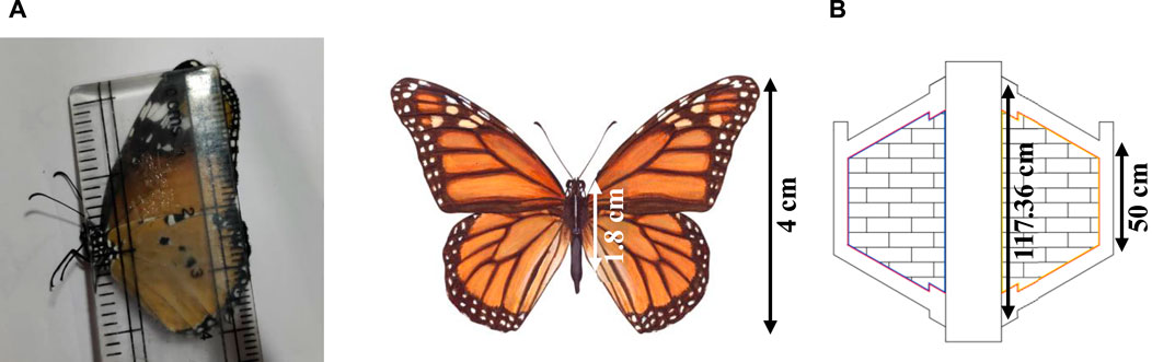
FIGURE 9. Ratio of wing dimensions (biomimicry from butterfly); (A) ratio 1:2.2 represents flexibility, (B) ratio 1:2.3 represents stability.
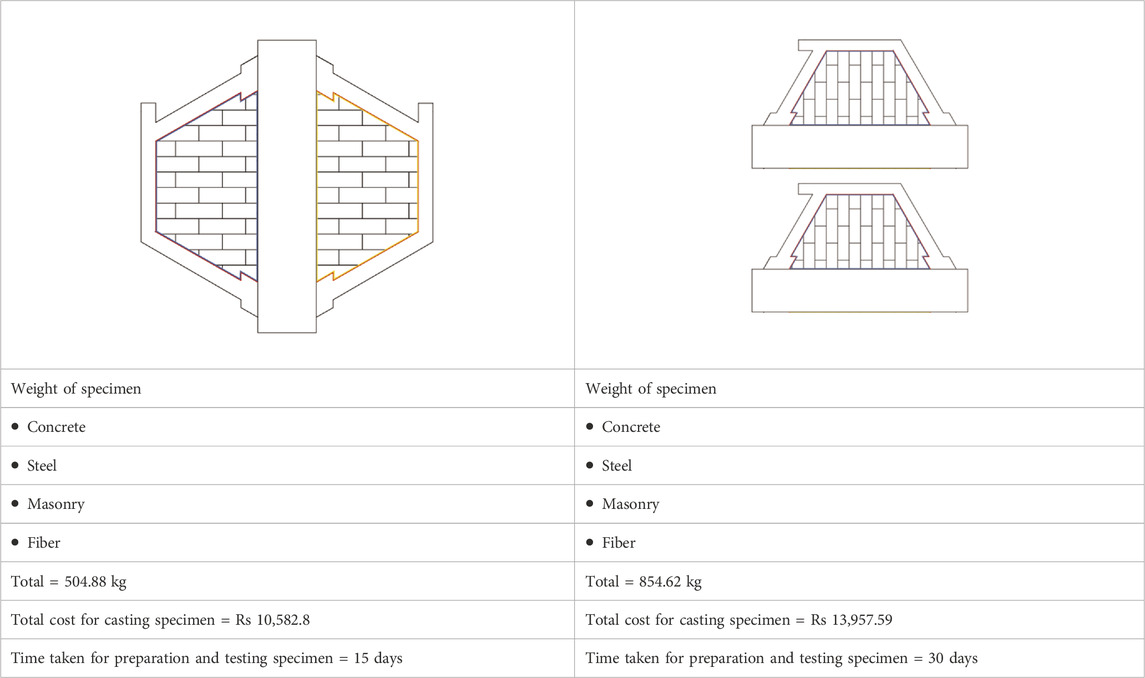
TABLE 6. Weight, cost, and time variations between two different types of frame design.
5.1 Analytical investigation
This behavior can also be computationally modeled using the finite element method. By breaking a structure down into a number of simple pieces, each with clearly defined mechanical and physical properties, the finite element analysis was done to identify the behavior of the structure. In the finite element analysis, the intricate behavior of RC, which is anisotropic and inhomogeneous, is difficult to model. Thus, software based on finite elements was employed for simplified modeling (Dash, 2018). To determine the strut width in real time, analysis was performed on both frames of different interface materials (cork and cement mortar), which were found to be critical under lateral loading. The strut widths of d/8 and d/9, respectively for the cement mortar and cork interface, were established in the previous analysis for the scale-down model. The strut width was analyzed for the trapezoidal bare frame and compared with the results for the trapezoidal infilled frame. The detailed dimensions of concrete frame and reinforcement for the scale-down model are displayed in Figures 10A,B. The thickness of the infilled panel was 75 mm. The properties of the interface material, such as the modulus of elasticity, Poisson’s ratio, and density, used for the analysis, are provided in Table 1. The frames were modeled to obtain the displacement and stiffness at the elastic stage. Figure 11 indicates a typical finite element model.
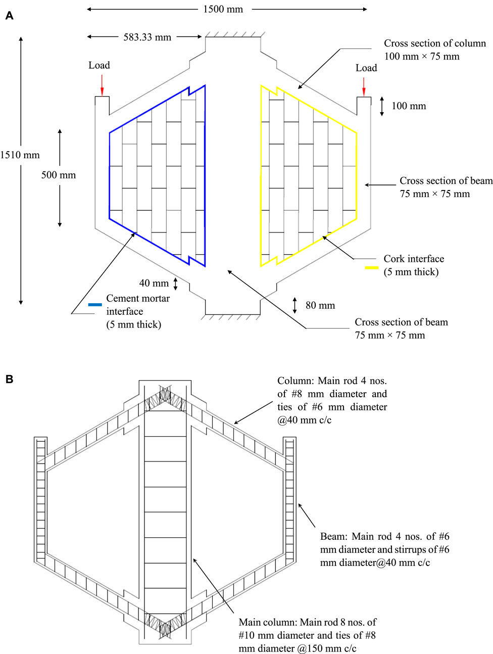
FIGURE 10. (A) Geometric details of single-bay single-storey for scale-down model, (B) Reinforcement details of single-bay single-storey for scale-down model of trapezoidal frame.
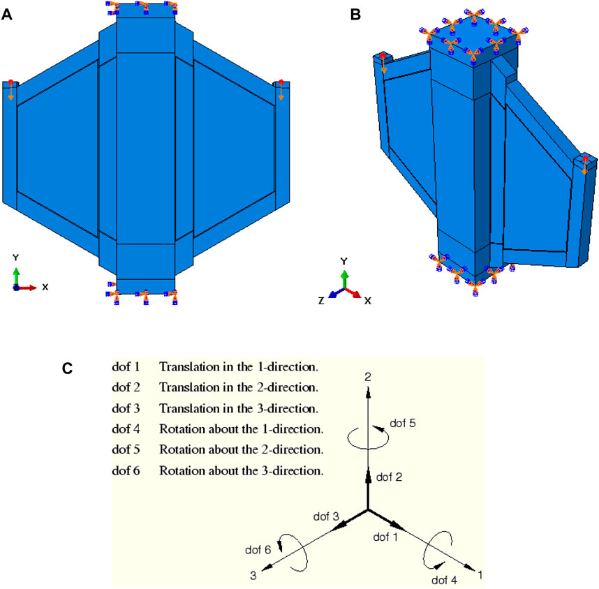
FIGURE 11. Typical finite element model of frame; (A) front view, (B) 3D view, (C) 3D directions.
5.2 Numerical results
For the numerical study, a point load was applied at the top of the left and right projection joints after performing the linear analysis. However, this research aims to provide an expression for the strut width for the elastic analysis and design of trapezoidal infilled frames, frames with inclined columns, which are scarce in the literature. Therefore, the linear elastic analysis was conducted in this study. The applied load was determined, and load–displacement curves were plotted for the two different types of frames. In the frames where the load was gradually increased and then filled, distortion was more easily observed. It was found that the displacements of the RC frames decreased with the induction of the infilled panel. The displacement and stiffness values are summarized in Table 7.

TABLE 7. Comparison of displacement.
5.3 Experimental test
The present experimental study investigated a trapezoidal infilled frame with cement mortar interface (TIFCM) and a trapezoidal infilled frame with cork interface (TIFC).
5.4 Preparation of specimen
A wooden frame was prepared and placed on a clean, smooth, and non-absorbent surface. The inside of the formwork was lubricated well to prevent concrete from sticking. Suitable precautions were taken to prevent cement slurry from coming out of the mold. The fabricated mold and reinforcement were positioned on the side and bottom of the inner mold, respectively, as depicted in Figures 12A,B. The frame was constructed from RC of ordinary Portland cement grade 53, as per IS 12269 (2013). According to IS 383 (1970), the specific gravity of river sand is 2.65 and is classified as Class II. With the specific gravity of 2.85, coarse aggregates with the nominal size of 10 mm were employed. Portable water was used with a concrete mix ratio of 1:1:65:1:67 with w/c of 0.45, as per IS 10262 (2009). The materials were mixed thoroughly by a 0.25 m3 mixer machine until it gave a uniform appearance. After concrete was ready, the mold was filled with the mix in 3 layers and compacted employing a needle vibrator Some stages of casting specimens are shown in Figures 12C–E. The frame was kept in a mold for one full day. After 24 h, the mold was removed from the frame specimen. Gunny bags were used to cure the frame. The frame was taken for infilling after 21 days of curing. The frame was transported and placed on the loading frame, which had the capacity of 400 kN, using a forklift, as illustrated in Figure 12F. Brick masonry was employed to infill two parts of the frame, with a cement mortar interface and with a cork interface. Cut bricks with the dimensions of 100 mm × 65 mm × 70 mm were used. Well-soaked cut bricks and cement mortar were utilized at a ratio of 1:4 with a joint thickness of 5 mm. The bricks were cut into the desired shapes at the inclined corners of the trapezoidal frame. Initially, the centerline would be marked inside the frame, as the center thickness of brick should coincide with the marked centerline inside the frame. At the interface, cement mortar with a thickness of 5 mm was placed around four sides of the frame. In the other part of the frame, a cork interface material with a sheet thickness of 5 mm was placed on all four sides of the frame. The infilling process was then performed. Plastering was conducted on both sides of the infill to obtain an even surface. The infilling process is displayed in Figure 12G. After infilling, curing was performed by spraying water three times a day for 7 days. After the seventh day of curing, the testing setup was arranged.
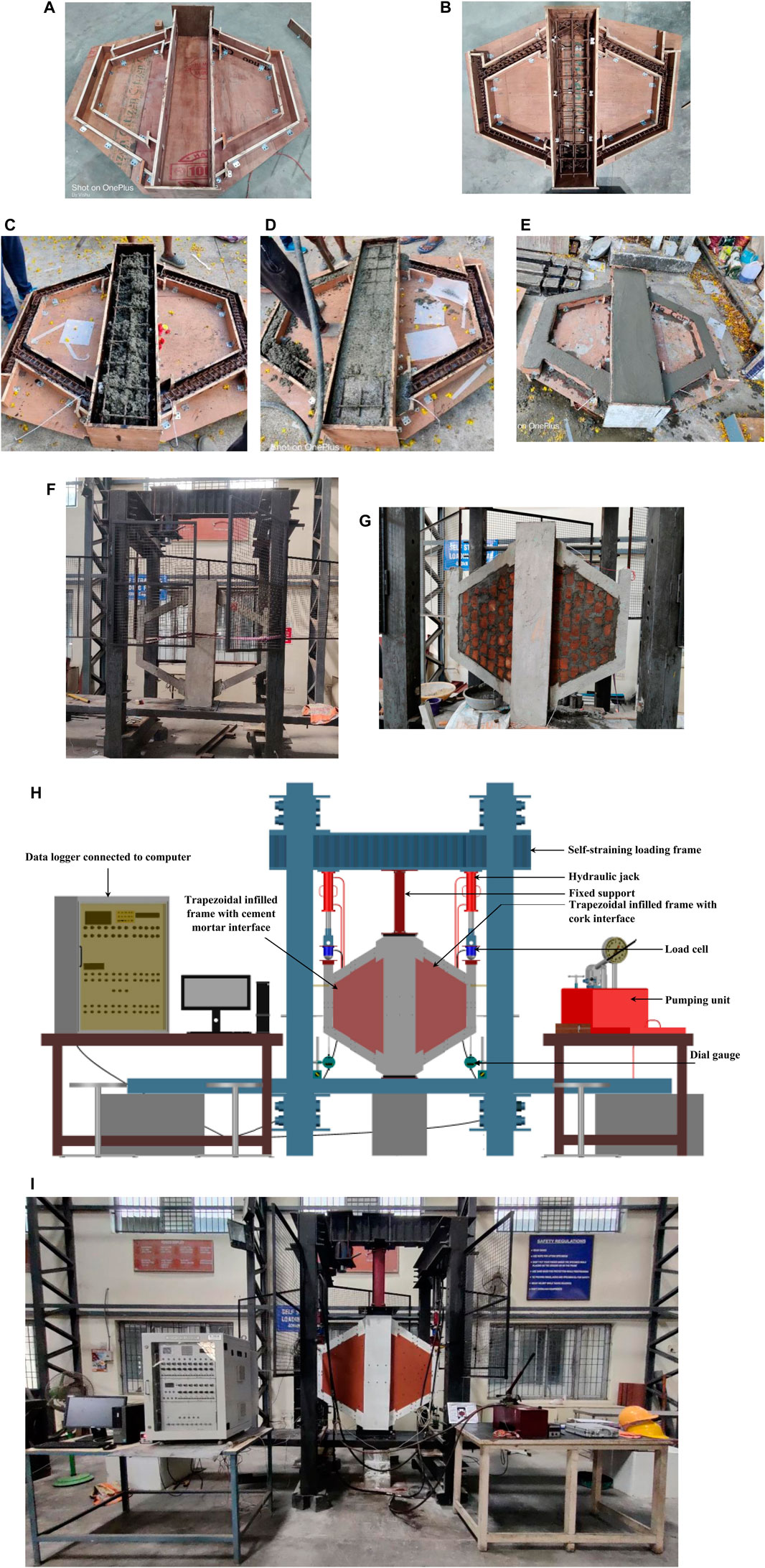
FIGURE 12. Preparation of specimens; (A) fabricated mold, (B) reinforcement cage, (C) initial stage of casting, (D) casting in progress, (E) final finishing of casting, (F) specimen on loading frame, (G) process of infilling, (H) schematic experimental test setup and instrumentation, (I) experimental test setup.
The surface moisture from the specimen was wiped off one day prior to the testing date and then washed white. A self-straining loading frame was utilized to test the specimen. The load cell was connected to a hydraulic jack, which was connected to the self-straining loading frame. This helped transfer the load without effectively transferring the moment to the specimen. The connections at the upper and lower sides of the column were fixed against the rotation at the base. The load cells were connected to a data logger to record the loads. The dial gauges were fixed at the bottom of the frame to calculate displacements. The schematic experimental test setup and instrumentation for testing the trapezoidal infilled frame is demonstrated in Figure 12H. The experimental setup for testing the 2D frame is presented in Figure 12I.
5.5 Experimental results
The readings from the experiments were processed, and the behavior of the frame was studied by comparing the initial crackings, crack patterns, ultimate loads, load–displacement curves, stiffness values, and strains, which are presented in the following sections.
5.5.1 Initial cracking loads and crack patterns
At a load of 10 kN, the trapezoidal frame with a cork interface cracked near the underside of the support column connection. As the load increased, a crack appeared at the cork interface at point C (Figure 13). As it progressed, a flexural crack appeared along BA near B outside, as indicated in Figure 13A. The critical moment value for a unit load was calculated from the linear analysis, and the cracking strength of the column section was calculated from the elastic analysis. According to the analysis, it was estimated that the theoretical load, causing the flexural crushing at C, was 6.05 kN. From the observations, the experimental critical crack was observed to be 10 kN, and the ratio between the experimental and analytical values was 10/6.05, which was equal to 1.65.
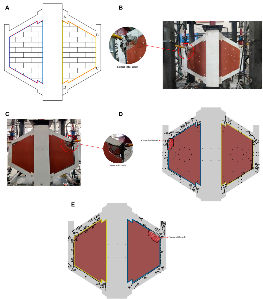
FIGURE 13. Cracking of specimens; (A) specimen with cracking positions, (B) typical cracking pattern of TIFCM and TIFC (front view), (C) typical cracking pattern of TIFCM and TIFC (back view), (D) schematic diagram for cracking pattern of TIFCM and TIFC (front view), (E) schematic diagram for cracking pattern of TIFCM and TIFC (back view).
The trapezoidal infilled frame with the cement mortar interface cracked horizontally at the base of the beam-column joint under the load of 17 kN. As the load continued to increase, the interface material separated the infill from the frame, and the frame behaved as a bare frame. According to the theoretical calculations, the first initial cracking load was likely to be 6.05 kN. The ratio of the experimental value to the analytical value was 2.81. Typical and schematic cracking patterns, as well as crushing failure, are depicted in Figures 13B–E.
5.5.2 Ultimate load
Table 8 provides the experimental and theoretical ultimate loads of the frames. The theoretical values are referred to the rectangular infilled frame with a cement mortar interface using the Smith (1967) and Liauw (1972) methods. This comparison points out that the theoretical values were close to the observed experimental ultimate loads.

TABLE 8. Ultimate loads of single-bay single-storey trapezoidal infilled frame.
5.5.3 Load–displacement behavior
The typical load–displacement curves of the tested frame are shown in Figures 14A,B. The results of the analytical investigation are illustrated in Figure 14C. The analytical curve using a rigorous approach by modeling the infill as plane stress elements, as well as the strut frame with effective width ratios corresponding to the λh value of 2.18 have been included.
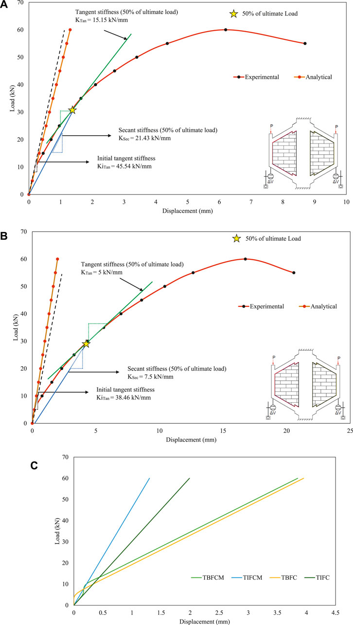
FIGURE 14. Load–displacement curves; (A) experimental load–displacement curve for TIFCM, (B) experimental load–displacement curve for TIFC, (C) analytical load–displacement curve.
5.5.4 Validation of numerical models with experimental results
The comparisons of the experimental and analytical load–displacement curves for the trapezoidal infilled frame with cement mortar and cork interface are illustrated in Figures 15A,B. This indicated that the curve was linear until the initial cracking load for both experimental and analytical approaches. After the initial cracking load, the experimental curve appeared non-linear.
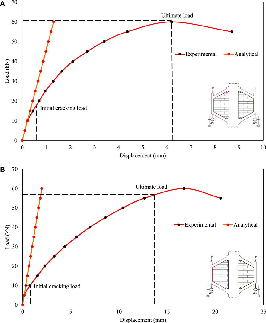
FIGURE 15. Comparison of load–displacement curves of analytical and experimental works; (A) TIFCM, (B) TIFC.
5.5.5 Comparison of stiffness
Table 9 compares the obtained experimental and analytical stiffness values for the trapezoidal infilled frame. The provision of inclined columns to the trapezoidal frame increased the in-plane racking stirrups. Adding infill to this frame enhanced the stiffness due to the strut action, which subsequently can increase the quantum seismic load that is used for the design of such frames because the infills are treated only as dead loads. In this research, this enhancement in the stiffness due to the infilled frame action was regulated by using soft materials such as cork, which makes the frame behave like a bare frame in spite of an infilled frame. This is the main reason for the major distinct failure pattern change between a rectangular infilled frame and trapezoidal infilled frame with soft interface material.
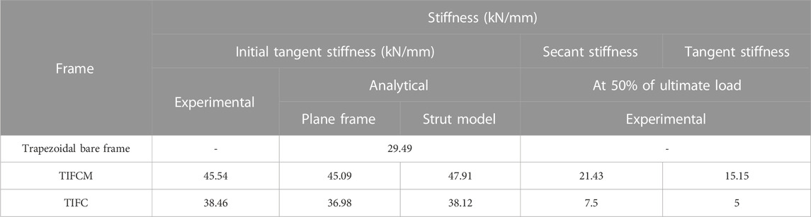
TABLE 9. Comparison of stiffness values of single-bay single-storey trapezoidal infilled frame.
Figure 16 demonstrates the main concept of the present work. According to the elastic design and analysis, the actual frame, which is a trapezoidal infilled frame with cement mortar and a horizontal load, is equal to the pin joint strut frame.

FIGURE 16. Trapezoidal infilled frame for elastic design and analysis; (A) actual frame, (B) pin joint strut frame.
6 Conclusion
Infilled frame concepts are extensively utilized to resist lateral loads, particularly in earthquake-prone regions. From the analytical investigation, it was found that the trapezoidal infilled frame had higher lateral stiffness than the rectangular infilled frame. The base shear was higher for the trapezoidal infilled frame, which needs to be considered when designing the frame members. The reduction in the base shear in a trapezoidal infilled frame was induced by the use of soft materials such as corks at the interface, which made the frame behave like a bare frame for which the base shear was lower than that of the infilled frame with cement mortar at the interface.
The present study examined the performance of frames using both numerical and experimental approaches.
• First, an analysis of the strut width was done for trapezoidal frames with different interfaces. It was observed that the pressure intensity of the infill increased with different interface materials, and the width of the strut and the reaction force applied to the equivalent frame decreased.
• Based on these findings, it can be inferred that the strut width of the trapezoidal infilled frame with a cement mortar interface was 1.1 times greater than that of the trapezoidal infilled frame with a cork interface for both prototype and scale-down models.
• NBJ had higher modulus of elasticity (1063 N/mm2) than IBJ (840 N/mm2) since the stresses were directly normal and produced less shear stresses because the load was perpendicular to the bed joint. Therefore, this direction appeared to be the strongest loading direction for the mortar joints.
• The strength of IBJ was lower than that of NBJ. This was because shear stresses were absent over NBJ.
• From the validation results, it was witnessed that the deformation patterns and displacements of the finite element method were similar to those of the experimental results.
Further investigation was done using a one-sixth scale-down model. To determine the strut width in real time, a trapezoidal infilled frame with two different interface materials was modeled and analyzed using both experimental and analytical approaches. The strut widths of d/8 and d/9 were considered for the cement mortar and cork interfaces, respectively, during the initial stage. A detailed analytical investigation was conducted, and it was concluded that this model of the frame did not differ in displacement from the original frame. However, studies on this type of testing are limited. According to the linear analysis, the displacement of the RC frame decreased with the introduction of the infilled panel.
• It was found that the trapezoidal infilled frame with the cement mortar interface was stiffer than the trapezoidal infilled frame with the cork interface.
• According to the analytical study of the plane frame, the initial tangent stiffness of TIFCM was 0.8 times lower than TIFC.
• In the strut model, the initial tangent stiffness of TIFCM was 0.8 times lower than TIFC.
• The secant stiffness was 0.7 times higher than the tangent stiffness for both cases of the interface materials.
• The ultimate loads were obtained as 60 kN and 58 kN for the trapezoidal infilled frame with the cement mortar and cork interfaces, respectively.
• The trapezoidal infilled frame with the cement mortar interface exhibited an infill corner crush near the loading area. However, no such issue was encountered in the case of the trapezoidal infilled frame with the cork interface, and separation occurred between the frame and infill, which seemed to be the major failure.
• The validation of the numerical models was done with the experimental results.
Data availability statement
The original contributions presented in the study are included in the article, further inquiries can be directed to the corresponding authors.
Author contributions
Conceptualization, MV and AB; methodology, MV, AB, and KS.; validation, AB, MP, and VT; formal analysis, AB; investigation, MV, AB, KS, and MP; resources, MV, AB, KS, and MP; software, MV, AB, and MP; visualization, MV, AB, KS, VT, and MP; writing–original draft, MV and AB; writing–review and editing, AB, KS, VT, and MP. Project administration: MV, AB, and VT. All authors contributed to the article and approved the submitted version.
Conflict of interest
The authors declare that the research was conducted in the absence of any commercial or financial relationships that could be construed as a potential conflict of interest.
Publisher’s note
All claims expressed in this article are solely those of the authors and do not necessarily represent those of their affiliated organizations, or those of the publisher, the editors and the reviewers. Any product that may be evaluated in this article, or claim that may be made by its manufacturer, is not guaranteed or endorsed by the publisher.
References
Cao, X. Y., Feng, D. C., Wu, G., and Zeng, Y. H. (2020). Reusing & replacing performances of the AB-BRB with thin-walled concrete-infilled steel shells. Thin-Walled Struct. 157, 107069. doi:10.1016/j.tws.2020.107069
Chetchotisak, P., Chomchaipol, W., Teerawong, J., and Shaingchin, S. (2021). Strut-and-tie model for predicting shear strength of squat shear walls under earthquake loads. Eng. Struct. 256, 114042. doi:10.1016/j.engstruct.2022.114042
Dash, S. P. (2018). Application of biomimicry in building design. Int. J. Civ. Eng. Technol. 9 (2), 644–660.
De Lorenzis, J. T. L., and Teng, J. (2007). Near-surface mounted frp reinforcement: an emerging technique for strengthening structures. Compos. Eng. 38, 119–143. doi:10.1016/j.compositesb.2006.08.003
FEMA (Federal Emergency Management Agency) (2000). Seismic isolation and energy dissipation (09-systematic rehabilitation). Washington, DC: FEMA-273.
Holmes, M., Smith, B. S., Mainstone, R. J., Wood, R. H., and Sachanski, S. (1962). Discussion. Steel frames with brickwork and concrete infilling. Proc. Inst. Civ. Eng. 23 (1), 93–104. doi:10.1680/iicep.1962.10925
IS 10262 (2009). Recommended guidelines for concrete mix design. New Delhi: Bureau of Indian Standards.
IS 12269 (2013). Specification for 53 grade ordinary portland cement reaffirmed 1999. New Delhi: Bureau of Indian Standards.
IS 383 (1970). Specification for coarse and fine aggregates from natural sources for concrete. New Delhi: Bureau of Indian Standards.
Liauw, T. C. (1972). An approximate method of analysis for infilled frames with or without opening. Build. Sci. 7, 233–238. doi:10.1016/0007-3628(72)90004-7
Motovali Emami, S. M., Mohammadi, M., and Lourenço, P. B. (2017). Equivalent diagonal strut method for masonry walls in pinned connection and multi-bay steel frames. J. Seismol. Earthq. Eng. 19, 4. Available: www.jseeonline.com.
Muthu kumar, S. (2019). Studies on the behaviour of infilled frames with different interface materials under static cyclic loading doctor of philosophy faculty of engineering and technologyPhD thesis. Chennai, India: SRM University.
Muthu Kumar, S., Joson Western, J., and Satyanarayanan, K. S. (2016). Nonlinear analysis of stresses for two bay three storeyed reinforced concrete infill frame. Int. J. Chem. Sci. 14, 79–87.
Muthu Kumar, S., and Satyanarayanan, K. S. (2018). Study the effect of elastic materials as interface medium used in infilled frames. Mater. Today, Proc. 5 (2), 8986–8995. doi:10.1016/j.matpr.2017.12.343
Muthu kumar, S., Satyanarayanan, K. S., and Senthil, K. (2017). Studies on two bay and three storey infilled frame with different interface materials: experimental and finite element studies. Struct. Eng. Mech. 64 (5), 543–555. doi:10.12989/sem.2017.64.5.543
Muthu kumar, S., Thirumurugan, V., Satyanarayanan, K. S., Thiyagarajan, G., and Jia, J. (2015). “Experimental studies on the behaviour of square infilled frames with different infill and interface materials under static cyclic loading,” in IMTCE 2015 -national conference on inventive materials & techniques in civil engineering (Kalasalingam University,Viruthunagar ,Tamilnadu: IMTCE). Avaliable at: https://www.researchgate.net/publication/313035278.
Pohoryles, D. A., and Bournas, D. A. (2020). A unified macro-modelling approach for masonry-infilled RC frames strengthened with composite materials. Eng. Struct. 223, 111161. doi:10.1016/j.engstruct.2020.111161
Riddington, J. R., and Sahota, M. K. (1999). Stability of lead alloy compressive work hardening. Mater. Des. 20 (1), 13–17. doi:10.1016/s0261-3069(98)00044-2
Sandoli, A., Musella, C., Piero Lignola, G., Calderoni, B., and Prota, A. (2020). Spandrel panels in masonry buildings: effectiveness of the diagonal strut model within the equivalent frame model. Structures 27, 879–893. doi:10.1016/j.istruc.2020.07.001
Satyanarayanan, K. S. (2009). Studies on the influences of different materials on the elastic behaviour of infilled frames. PhD thesis. Chennai, India: SRM University.
Satyanarayanan, S., Krishnamoorthy, C. S., Achyutha., H., and Injaganeri, S. S. (1994). Inelastic behaviour of brick infilled reinforced concrete frames. J. Struct. Eng. 21 (2), 107–115.
Senthil, K., Muthukumar, S., Rupali, S., and Satyanarayanan, K. S. (2018). Effect of various interface thicknesses on the behaviour of infilled frame subjected to lateral load. IOP Conf. Ser. Mater. Sci. Eng. 330, 012113. doi:10.1088/1757-899X/330/1/012113
Silva, S. P., Sabino, M. A., Fernandas, E. M., Correlo, V. M., Boesel, L. F., and Reis, R. L. (2005). Cork: properties, capabilities and applications. Int. Mater. Rev. 50 (6), 345–365. doi:10.1179/174328005X41168
Smith, B. S. (1967). Methods for predicting the lateral stiffness and strength of multi-storey infilled frames. Build. Sci. 2 (3), 247–257. doi:10.1016/0007-3628(67)90027-8
Smith, B. S., Carter, C., and Mallick, D. (1970). Discussion. A method of analysis for infilled frames. Proc. Inst. Civ. Eng. 46 (2), 229–231. doi:10.1680/iicep.1970.6801
Srechai, S. L., Leelataviwat, S., Wararuksajja, W., and Limkatanyu, S. (2022). Multi-strut and empirical formula-based macro modeling for masonry infilled RC frames. Eng. Struct. 266, 114559. doi:10.1016/j.engstruct.2022.114559
Srishti, M. (2022). Japanese Architecture Trends. Avaliable at: https://www.yankodesign.com/2022/02/10/top-10-japanese-architecture-trends-of-2022/.
Vishali, M., Satyanarayanan, K. S., and Thirumurugan, V. (2021). Analytical investigation on the development of adaptive infilled gabled frames. Mater. Today, Proc. 50, 269–272. doi:10.1016/j.matpr.2021.06.321
Zhang, Y., Wei, Y., Bai, J., and Zhang, Y. (2019). Stress-strain model of an FRP-confined concrete filled steel tube under axial compression. Thin-Walled Struct. 142 (159), 149–159. doi:10.1016/j.tws.2019.05.009
Keywords: infilled frame, trapezoidal frame, equivalent diagonal strut, interface materials, stiffness, biomimicry
Citation: Vishali M, Bahrami A, Satyanarayanan KS, Thirumurugan V and Prakash M (2023) Effects of using different materials at interface of trapezoidal reinforced concrete infilled frames–analytical and experimental approaches. Front. Mater. 10:1239312. doi: 10.3389/fmats.2023.1239312
Received: 13 June 2023; Accepted: 22 August 2023;
Published: 01 December 2023.
Edited by:
Zhigang Zhang, Chongqing University, ChinaReviewed by:
Ernesto Grande, Università degli Studi Guglielmo Marconi, ItalyXiaoqing Xu, Tongji University, China
Jun He, Changsha University of Science and Technology, China
Copyright © 2023 Vishali, Bahrami, Satyanarayanan, Thirumurugan and Prakash. This is an open-access article distributed under the terms of the Creative Commons Attribution License (CC BY). The use, distribution or reproduction in other forums is permitted, provided the original author(s) and the copyright owner(s) are credited and that the original publication in this journal is cited, in accordance with accepted academic practice. No use, distribution or reproduction is permitted which does not comply with these terms.
*Correspondence: Alireza Bahrami, YWxpcmV6YS5iYWhyYW1pQGhpZy5zZQ==; Mugunth Vishali, dmlzaHVtdWd1bnRoQGdtYWlsLmNvbQ==