 Junxia Lian
 Dongjie Li2*
- 1Qinyang Water and Drought Disaster Prevention Service Center, Qinyang Water Resources Bureau, Jiaozuo, China
- 2The Power China Huadong Engineering Corporation Limited, Hangzhou, China
- 3School of Water Conservancy and Transportation, Zhengzhou University, Zhengzhou, China
To study the damage characteristics and damage model of reinforced concrete slabs under explosive impact, the failure modes of reinforced concrete slabs under near-field and contact explosion were first studied through on-site experiments. A coupled model was established based on the Coupled Eulerian-Lagrangian (CEL) method using AUTODYN finite element software. The reliability of the model was verified by comparing the numerical simulation results with experimental results. Based on this, a fully coupled model of Carbon Fiber Reinforced Polymer (CFRP) reinforcement for reinforced concrete slabs under contact explosion was established, and the influence of different CFRP thicknesses and reinforcement methods on the blast resistance performance of reinforced concrete slabs was discussed. The research results indicate that under the action of near-field explosions, the front face of reinforced concrete slabs mainly experiences slight peeling damage, and the central area of the back face forms seismic collapse and peeling damage, with damage cracks diverging from the center to the surrounding areas; Under the action of contact explosion, the front face of the reinforced concrete slab produces blast pits, the back face forms a seismic collapse zone, and peeling damage occurs; The CFRP reinforcement layer can improve the blast resistance performance of reinforced concrete slabs; There is an optimal thickness when using CFRP to enhance the blast resistance of reinforced concrete slabs.
1 Introduction
As a common primary building material, reinforced concrete has been widely used in protective structures, nuclear power plants, and engineering projects. However, the increasingly frequent occurrences of terrorist attacks and explosive incidents both at home and abroad, pose a serious threat to the safety of society’s production, life, and people’s lives and property. In response to the structural collapses and significant casualties caused by terrorist attacks or chemical explosions, researching the damage characteristics of reinforced concrete structures under explosive impact, and implementing anti-explosion protective designs is of vital importance. This ensures that reinforced concrete structures not only have sufficient strength but also possess certain continuity and ductility (Wang et al., 2016), which holds significant importance.
CFRP as a strengthening material can fully exploit its high strength and high modulus properties to enhance the load-bearing capacity of components, optimize their stress conditions, and achieve efficient reinforcement effects. During reinforcement, carbon fiber cloth is effectively bonded to the original components through bonding materials such as epoxy resin. It can effectively close cracks on the surface of concrete, while also limiting the generation and propagation of cracks in concrete structures. Additionally, carbon fiber materials have good heat resistance, and their chemical properties are highly stable, as they do not react with chemicals such as acids, alkalis, and salts, exhibiting excellent durability (Lu et al., 2024). Existing research results indicate that reinforcing concrete structural components with CFRP materials can significantly enhance the structures’ impact resistance, reduce the damage consequences of explosive shockwaves, and hold vital research value (Chen et al., 2020a; Reifarth et al., 2021; Maazoun et al., 2019; Maazoun et al., 2018; Wang et al., 2017). Domestic and foreign scholars have conducted relevant research and exploration on the influence of CFRP on the blast resistance of structures (Tu et al., 2024; Huang et al., 2024; Rafat et al., 2023; Chen and Chen 2022; Vimal et al., 2023; Cui et al., 2022). (Chen et al., 2022b) carried out numerical simulation studies on the dynamic response of CFRP-strengthened reinforced concrete T-beams under blast loading, investigating the effects of CFRP application forms and thickness on the blast resistance of reinforced concrete T-beams (Zheng, 2022). studied the blast resistance of CFRP-reinforced gravity dams under underwater explosive impacts through numerical simulations (Zhao et al., 2021), (Guan et al., 2021), and others have studied the influence of CFRP strengthening on the blast resistance of reinforced concrete arch structures through numerical simulations. The research findings indicate that CFRP reinforcement can effectively improve the overall load-bearing performance of structural components and mitigate structural damage (Hu et al., 2021). investigated the blast resistance of CFRP-strengthened reinforced concrete columns using experimental and numerical simulation methods, conducting tests on the residual load-carrying capacity of damaged columns after explosive impacts (Niu et al., 2006). explored the impact of the structural form of carbon fiber composite materials on reinforced concrete slabs (Dong, 2019) and (Chen et al., 2020b). conducted studies on the blast resistance of CFRP-strengthened reinforced concrete slabs through numerical simulations, revealing that externally bonded CFRP strips can significantly delay the development of concrete cracks, thereby postponing the onset of structural failure. Currently, both domestic and foreign scholars have conducted extensive research on the blast resistance of CFRP-strengthened concrete columns, yielding fruitful results. However, studies on the blast resistance of CFRP-strengthened reinforced concrete slabs are relatively limited. Given that reinforced concrete slabs are a crucial component of industrial and civil buildings, reinforcing them and investigating their blast resistance hold significant importance.
This study investigates the failure modes of reinforced concrete slabs under explosive impacts through on-site explosion tests. An aerial contact explosion fully coupled model for reinforced concrete slabs is developed using AUTODYN software. The numerical simulation results are compared with experimental data to verify the model’s reliability. Building upon this validation, a fully coupled model for three different CFRP reinforcement methods for reinforced concrete slabs under contact explosions is established. The study discusses the influence of varying CFRP thicknesses and reinforcement methods on the blast resistance performance of reinforced concrete slabs. The optimal reinforcement method for using CFRP to reinforce reinforced concrete slabs has been proposed.
2 Field test
2.1 Specimen preparation
The dimensions of the reinforced concrete slab used in the experiment are 500 × 500 × 80 mm. In each specimen, five steel bars with a diameter of 4 mm are arranged in a single layer bidirectionally at a spacing of 120 mm (as shown in Figure 1), the concrete protective layer is 2 cm. The yield strength of the steel bars is 400 MPa, and Young’s modulus is 200 GPa. After casting in molds, the specimens were cured in standard curing tanks for 28 days. According to the “Standard for Inspection and Evaluation of Concrete Strength” (GB/T 50107-2010), the compressive strength of the concrete is determined to be 35 MPa based on testing concrete cube specimens.
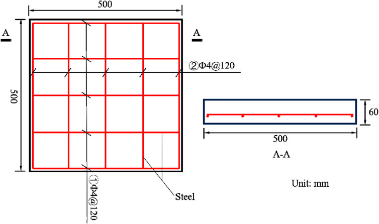
Figure 1. Geometric dimensions of reinforced concrete slabs.
2.2 Experimental setup
In the experiment, the reinforced concrete specimens are placed on a specially designed steel frame with the ends of the specimens fixed. The steel frame, made of welded U-shaped steel, has upper grooves for specimen installation. The specimens are secured using screws and steel plates to provide approximate fixed boundary conditions. The experimental setup is shown in Figure 2. Three reinforced concrete slabs were tested in this experiment. Specimens S1 and S2 were subjected to near-field explosions with a charge center distance of 60 mm, while specimen S3 experienced a contact explosion with #2 rock emulsion explosive placed at the central upper part of the reinforced concrete slab, ignited using electric detonators. Refer to Table 1 for specific experimental arrangements.
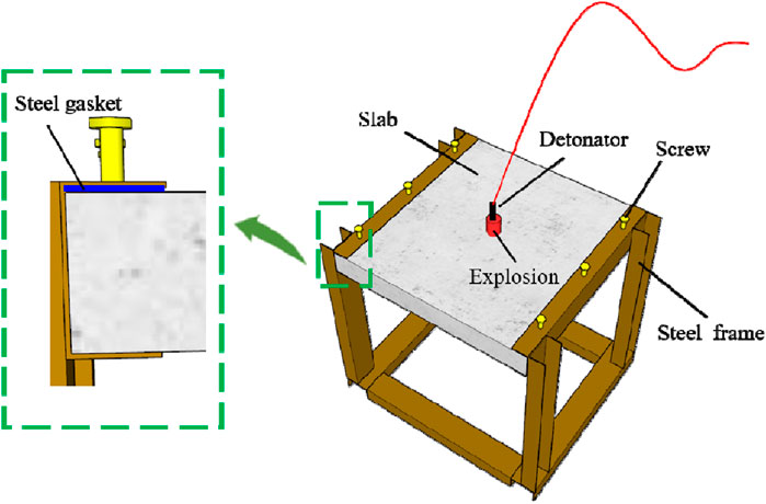
Figure 2. Schematic diagram of the testing device.
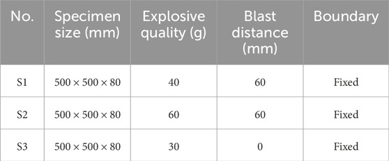
Table 1. Test setup.
2.3 Discussion and analysis of experimental results
Figure 3 shows the damage results of the three reinforced concrete specimens under explosive loading. From Figure 3A, it can be observed that under the effect of a 40 g explosive charge, specimen S1 exhibits no significant damage on the top surface, with some tension cracks appearing on the bottom surface, and a plastic tensile failure zone in the central region of the reinforced concrete slab. This is attributed to the compression stress wave formed on the top surface after the explosion, with its peak value lower than the compressive strength of concrete, thus causing no damage on the bottom surface. The compression stress wave reflects on the bottom surface, generating tension stress waves with peak values exceeding the tensile strength of concrete, resulting in tension cracks on the bottom surface of the reinforced concrete slab. With an increase in charge size, when subjected to a 60 g explosive charge, slight spalling damage occurs on the top surface of the reinforced concrete slab, while collapse spalling damage occurs in the central region of the bottom surface along with some tension crack damage, as shown in Figure 3B.
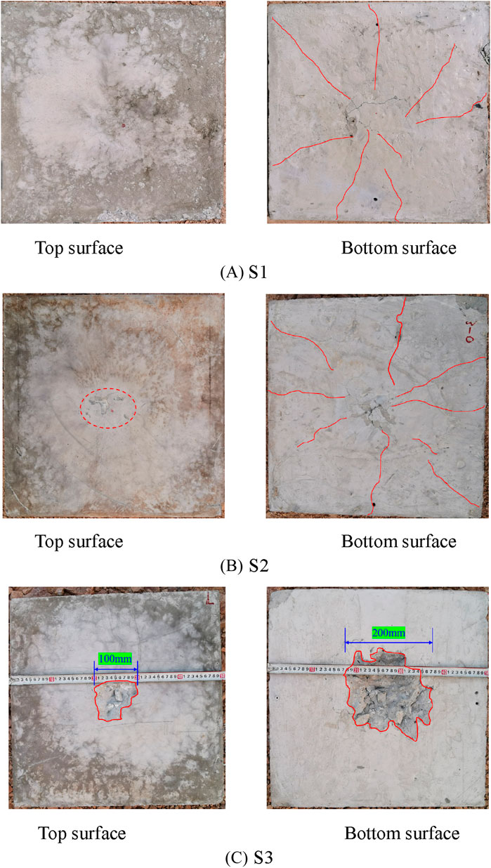
Figure 3. Damage results of reinforced concrete slab explosion test. (A) S1. (B) S2. (C) S3.
Under the effect of a contact explosion, the explosive load generates significant triaxial compressive stress on the top surface of the reinforced concrete slab, leading to local damage on the top surface, and forming a crater. A portion of the impact wave energy is reflected, while the remaining part continues to propagate into the slab. When the shock wave reaches the bottom surface of the reinforced concrete slab, tension stress is reflected on the bottom surface. If the tension stress exceeds the ultimate tensile strength of concrete, a collapse failure zone is formed on the concrete’s bottom surface, resulting in spalling and fragment ejection, as depicted in Figure 3C.
3 Numerical simulation
Due to the high risk and cost associated with on-site explosion tests, the next step will involve using finite element analysis software such as AUTODYN to continue the analysis. In the AUTODYN software calculation program, there are both Euler and Lagrange modules, which can conduct research on pure Euler, pure Lagrange, and fluid structure coupling problems.
3.1 Material model
3.1.1 Concrete
The RHT concrete material model is utilized to simulate the failure process of concrete structures under explosive impact, as outlined in references (Riedel et al., 2007; Ansys, 2018). This model comprises the p-α state equation, RHT strength model, RHT failure model, and erosion model. The RHT strength model incorporates three limit surfaces: elastic limit surface, failure surface, and residual strength surface. These surfaces characterize the variations in the yield strength, maximum strength, and residual strength of the concrete material, depicting the process from elastic strength to failure in concrete. This model can effectively simulate the dynamic characteristics of concrete under explosive impact. Specific parameters are provided in Table 2.
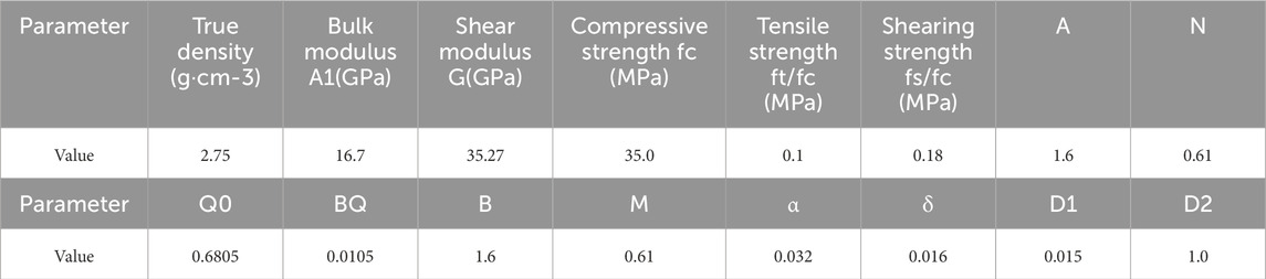
Table 2. Parameters of the concrete.
3.1.2 Rebar
The rebars utilize the Johnson-Cook constitutive model, which effectively simulates the mechanical behavior of the bars under explosive loading. In this model, the yield stress is defined as:
Where,

Table 3. Parameters of steel reinforcement.
3.1.3 Explosive
The explosive uses TNT and is described using the JWL equation of state, which is expressed as
where, P is the detonation pressure; V is the relative volume of explosive detonation products; Energy per unit volume E0 = 6.0 GJ/m3, ρ = 1,630 kg/m3, D = 6,930 m/s, A1 = 373.77 GPa, B1 = 375 GPa, R1 = 4.15, R2 = 0.95, ω = 0.35 (Yang et al., 2019).
3.1.4 Air
The air adopts a Mat-Null material model, and the Ideal Gas state equation is represented by Equation 4:
where P is the pressure,
3.1.5 CFRP
CFRP is considered a linear elastic material, and for its material model (Yang et al., 2019), the KFRP material available in AUTODYN is selected (Ryan et al., 2008). When the principal tensile stress or strain exceeds the tensile strength or fracture elongation, highly deformed elements are automatically removed from the model. The mechanical properties of the CFRP sheet used in this research are listed in Supplementary Table S4 (Zhang et al., 2015; Wang et al., 2016).
3.2 Explosion coupling model and model validation
The Coupling Euler Lagrange (CEL) algorithm was first proposed by Noh. Since its development, the CEL algorithm mainly uses Lagrange mesh to discretize structural objects and Euler mesh to discretize large deformation objects. The combination of the two can simultaneously solve the problems of large mesh deformation and difficulty in capturing fluid interfaces (Liang et al., 2013). Based on the Coupled Eulerian-Lagrangian (CEL) coupling method, a three-dimensional fully coupled model was established for research, as shown in Figure 4. Eulerian elements were used to represent the explosive and air, while Lagrange elements were employed for the concrete material. The interaction between air and concrete materials was described using a fluid-structure coupling method. Beam elements were utilized for the reinforcement bars, and they embedded in the concrete material at common nodes. The concrete unit type is 3D solid 8-node C3D8R and the steel reinforcement is 3D 2-node T3D2. The computational domain for air was set at 150 × 150 × 100 cm, with an Eulerian element grid size of 2 cm, and a concrete grid size of 1 cm. The concrete slab consists of 22,500 units, the steel reinforcement consists of 492 units, and the total number of Euler units is 60,0000. By filling TNT explosives in the air and setting the TNT center as the detonation point, an explosive load is generated. Previous studies have shown that the average TNT equivalent of rock emulsion explosive is 0.6–0.7 (Fan et al., 2011; Qiao et al., 1998). Therefore, the TNT equivalent of 30 g rock emulsion explosive used in contact explosion is about 20 g.
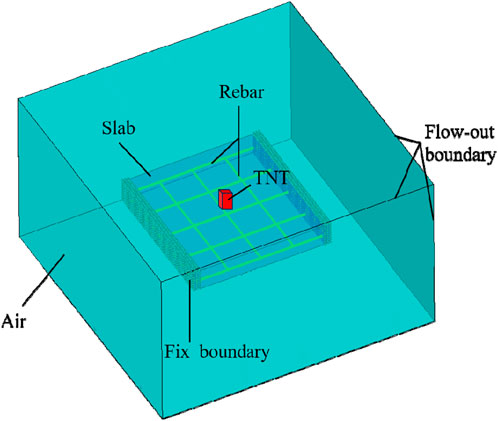
Figure 4. A fully coupled model for contact explosion of reinforced concrete slabs.
The comparison between the numerical simulation results and the on-site explosion test results is shown in Figure 5. From the figure, it can be observed that the diameter of the blast crater on the top surface of the concrete slab and the damage distribution in the spalling region on the bottom surface match well between the numerical simulation and the on-site explosion test results, the degree of conformity reaches over 95%. This indicates that the coupled computational method and material models used can effectively describe the damage characteristics and dynamic response of reinforced concrete slabs under explosive impact loads.
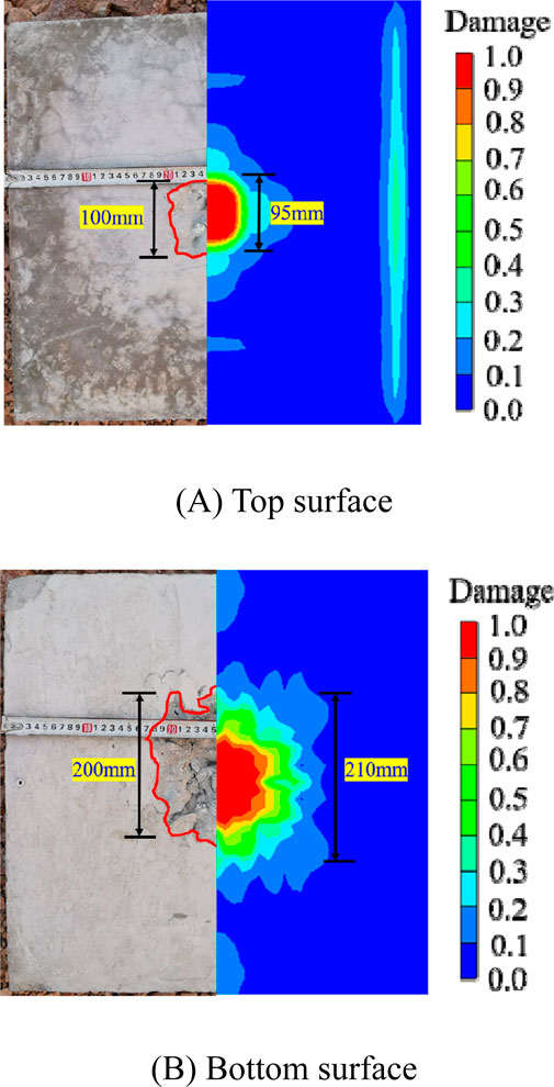
Figure 5. Comparison between numerical simulation results and experimental results. (A) Top surface. (B) Bottom surface.
3.3 Research on the blast resistance performance of reinforced concrete slabs reinforced with CFRP
3.3.1 A fully coupled numerical model for CFRP reinforced reinforced concrete slabs
In this study, coupled models were established for three different reinforcement methods: strengthening the blast face, strengthening the bottom surface, and strengthening both faces simultaneously, as depicted in Figure 6. The single-layer thickness of carbon fiber cloth used in this study is 0.5 mm, multi-layer CFRP cloth is treated as integration, and a perfect bond between the concrete and CFRP cloth in the numerical simulation is assumed. The CFRP cloth is modeled explicitly using the shell element. The positions of shell nodes coincide with those of concrete nodes, nodes of the CFRP cloth are attached to the concrete. Assuming good bonding between carbon fiber cloth and concrete material, there will be no detachment or failure between carbon fiber cloth and concrete before the structure reaches its ultimate bearing capacity. This assumption is reasonable because the current high-performance resin bonding materials and anchoring technologies can fully maintain good working performance between carbon fiber cloth and concrete structures. The thickness of CFRP reinforcement was chosen as 2, 4, and 6 mm. Shell elements were used to simulate the CFRP material, with common nodes between CFRP and concrete elements, and element coupling was achieved through “JOIN” constraints. Its boundary conditions are the same as before.
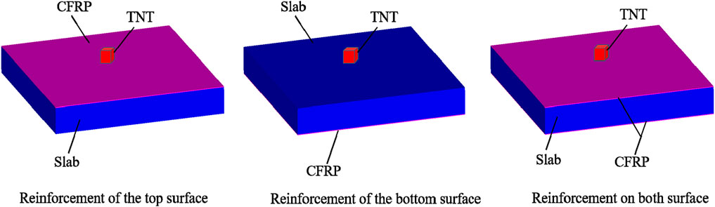
Figure 6. Numerical model of reinforced concrete slabs reinforced with CFRP.
3.3.2 Research on reinforcement effect
The study conducted multiple scenario simulations for the three different reinforcement methods, considering various thicknesses of CFRP reinforcement. Specific scenarios are detailed in Table 4 to investigate the impact of different reinforcement methods on the blast resistance of reinforced concrete slabs. The explosive charge size was consistent at 20 g TNT.
1) Reinforcement of the top surface
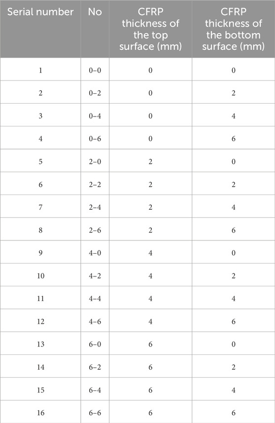
Table 4. Design of CFRP-protected reinforced concrete slab under working conditions.
CFRP reinforcement layers of 2, 4, and 6 mm were respectively applied to the top surface of the reinforced concrete slab to study the blast resistance performance under explosive loading. To analyze the displacement of the reinforced concrete slab, measurement points #1 and #2 were placed on the upper and lower surfaces of the slab. Figure 7 illustrates the locations of these measurement points, while Figure 8 shows the displacement-time curves at the center of the top surface and bottom surface of the reinforced concrete slab when CFRP reinforcement is applied to the top surface.
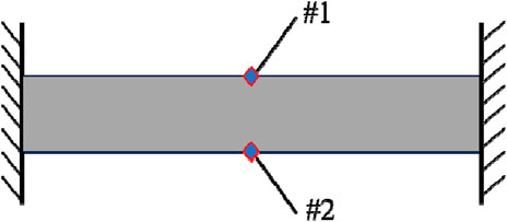
Figure 7. Schematic diagram of measurement point location.
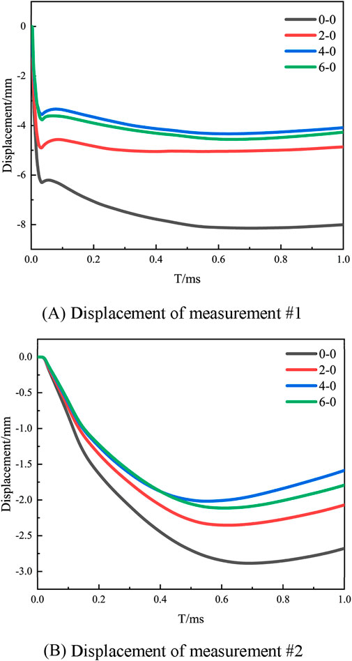
Figure 8. Displacement time history curves at the center of the top and bottom surfaces under different working conditions. (A) Displacement of measurement #1. (B) Displacement of measurement #2.
From Figure 8, it can be observed that when only the top surface is reinforced, the displacements at the centers of both the top surface and bottom surface are smaller compared to the unreinforced reinforced concrete slab, indicating that CFRP reinforcement enhances its blast resistance. Without CFRP reinforcement, the maximum displacement at the center of the bottom surface of the reinforced concrete slab is 2.873 mm. With CFRP reinforcement thicknesses of 2, 4, and 6 mm, the maximum displacements at the center of the bottom surface are reduced to 2.348, 2.024, and 2.057 mm, respectively. The maximum displacements are reduced by 18.27%, 29.55%, and 28.40% when compared to no CFRP reinforcement. This improvement is attributed to the increased stiffness provided by the CFRP reinforcement. However, it is evident from the figure that thicker CFRP reinforcement does not necessarily result in better blast resistance for the reinforced concrete slab. When the top surface has a CFRP thickness of 4 mm, both the top surface and bottom surface displacements are minimized, indicating that a 4 mm CFRP thickness provides optimal blast protection when solely reinforcing the top surface of the reinforced concrete structure.
2) Reinforcement of the bottom surface
CFRP reinforcements of 2, 4, and 6 mm were applied to the bottom surface of the reinforced concrete slab to investigate the effect of bottom surface CFRP reinforcement on the blast resistance of the reinforced concrete slab. Figure 9 provides displacement-time curves at the center of the top surface and bottom surface of the reinforced concrete slab when CFRP reinforcement is applied to the bottom surface.
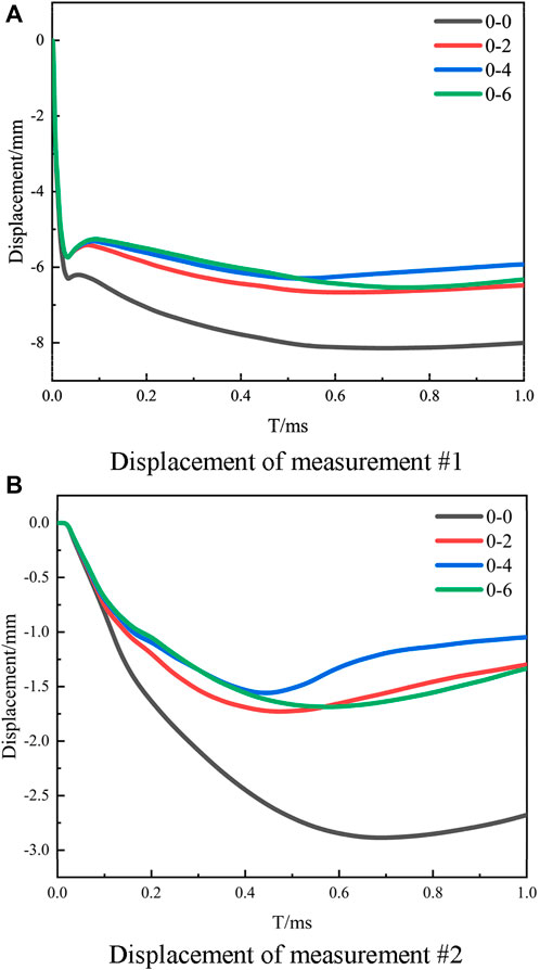
Figure 9. Displacement time history curves at the center of the top and bottom surfaces under different working conditions. (A) Displacement of measurement #1. (B) Displacement of measurement #2.
According to Figure 9A, it can be seen that setting CFRP on the back face of reinforced concrete slabs can reduce the displacement at the center of the top surface, but increasing the thickness of CFRP has little impact on the displacement at the center of the top surface. From Figure 9B, it is observed that when a CFRP reinforcement layer is applied to the bottom surface of the reinforced concrete slab, the displacement at the center of the bottom surface significantly decreases. Without CFRP reinforcement, the maximum displacement at the center of the bottom surface is 2.873 mm. With CFRP thicknesses of 2, 4, and 6 mm, the maximum displacements at the center of the bottom surface decrease to 1.657, 1.477, and 1.621 mm respectively. Compared to no CFRP reinforcement, the maximum displacements were reduced by 42.33%, 48.59%, and 43.58% respectively. This was because the bottom surface of the concrete slab undergoes tensile stresses leading to cracks, with the CFRP reinforcement layer taking on the original tensile stress at the corresponding position, resulting in plastic deformation and consequently reducing the displacement of the back face of the reinforced concrete slab. However, comparing the displacements at the center of the bottom surface with different thicknesses of CFRP reinforcement reveals that the minimum displacement occurs when a 4 mm CFRP reinforcement layer is applied to the bottom surface. This indicates that the maximum displacement at the center of the bottom surface of the reinforced concrete slab does not decrease monotonically with increasing CFRP thickness. Therefore, employing an optimal thickness of CFRP is essential for enhancing the blast resistance of reinforced concrete slabs, rather than blindly increasing the thickness of the reinforcement layer to improve blast resistance.
3) Reinforcement on both surface
When CFRP reinforcement layers are set on both sides of a reinforced concrete slab, the damage to the reinforced concrete slab is mainly due to the action of explosive stress waves. The stress wave’s transmission and reflection at the interfaces of CFRP and the concrete surface increase the structural capacity for blast energy absorption. Figure 10 shows the maximum displacement at the center of the top and bottom surfaces of the reinforced concrete slab when reinforced on both sides. It can be observed from the figure that when a 4 mm CFRP reinforcement is applied to the top surface and a 6 mm reinforcement to the bottom surface of the reinforced concrete slab, the maximum displacement at the center of the top and bottom surfaces is minimized. Compared to the unreinforced displacements of 8.143 and 2.873 mm, the displacements are reduced by 54.35% and 69.3% respectively. This indicates that using CFRP reinforcement on both sides can enhance the blast resistance of the reinforced concrete slab to a certain extent.
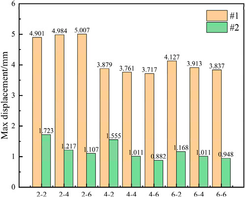
Figure 10. Maximum displacement at the center of the top and bottom surfaces under different working conditions.
4 Conclusion
The failure mode of reinforced concrete slabs under explosive impact was studied through experiments, and a numerical model of reinforced concrete slabs under contact explosion was established based on the CEL method. The reliability of the model was verified by comparing the numerical simulation results with the experimental results. The influence of different reinforcement methods of CFRP on the blast resistance performance of reinforced concrete slabs was studied through numerical simulation. The main conclusions are as follows:
1) Under the action of near-field explosions, the top surface of the reinforced concrete slab mainly experiences slight peeling damage, and the central area of the bottom surface forms seismic collapse and peeling damage, with damage cracks spreading from the center to the surrounding areas. Under the action of contact explosion, the top surface of the reinforced concrete slab produces explosion pits, and the bottom surface experiences local collapse and peeling damage.
2) Strengthening reinforced concrete slabs with CFRP can improve the blast resistance of reinforced concrete slabs, and the thicker the CFRP, the better the blast resistance of reinforced concrete slabs.
3) When using only the top surface reinforcement and only the bottom surface reinforcement, a CFRP reinforcement layer with a thickness of 4 mm has the best blast resistance effect on reinforced concrete slabs; When using double-sided reinforcement, the reinforced concrete slab has the best blast resistance when reinforced with 4 mm CFRP on the top surface and 6 mm on the bottom surface.
Data availability statement
The original contributions presented in the study are included in the article/Supplementary Material, further inquiries can be directed to the corresponding author.
Author contributions
JL: Conceptualization, Data curation, Methodology, Software, Writing–original draft, Writing–review and editing. DL: Data curation, Software, Supervision, Writing–original draft, Writing–review and editing. HZ: Conceptualization, Methodology, Resources, Supervision, Validation, Writing–original draft, Writing–review and editing.
Funding
The author(s) declare that no financial support was received for the research, authorship, and/or publication of this article.
Conflict of interest
Author DL was employed by The Power China Huadong Engineering Corporation Limited.
The remaining authors declare that the research was conducted in the absence of any commercial or financial relationships that could be construed as a potential conflict of interest.
Publisher’s note
All claims expressed in this article are solely those of the authors and do not necessarily represent those of their affiliated organizations, or those of the publisher, the editors and the reviewers. Any product that may be evaluated in this article, or claim that may be made by its manufacturer, is not guaranteed or endorsed by the publisher.
References
Chen, R. L., and Chen, X. H. (2022). Numerical simulation of explosion-resistant dynamic response of concrete T-beams reinforced by CFRP. Eng. Blasting 28 (01), 10–16.
Chen, R. L., Li, K., Dong, Q., Yu, B. B., Zhang, W. K., Zhang, X. C., et al. (2020a). Numerical simulation of dynamic response analysis of reinforced concrete slabs strengthened with CFRP under blast load. J. Rail Way Sci. Eng. 17 (06), 1517–1527.
Chen, R. L., Zhang, Z., Zhou, Z. Y., Zhou, S. S., et al. (2020b). Numerical analysis of anti-explosion response of CFRP-concrete-steel double skin tubular columns. Eng. Blasting 26 (06), 9–16.
Cui, Y., Zhao, J. H., Qu, Z., et al. (2022). Damage assessment of a buried CFRP petroleum pipeline subjected to blast loading. J. Vib. Shock 41 (06), 60–69.
Dong, Q. (2019). Numerical research on dynamic response of reinforced concrete slab strengthened with CFRP subjected to blast load. Xiangtan University.
Fan, J. Y., Fang, Q., Zhang, Y. D., and Chen, L. (2011). Experimental investigation on the TNT equivalence coefficient of a rock emulsion explosive. Acta Armamentarii 32 (10), 1243–1249.
Guan, L. Q., Wang, P., Zhou, J. N., Xu, Y., Zheng, E. H., Wang, B., et al. (2021). Influence of CFRP reinforcement on anti-explosion performance of reinforced concrete arch. Build. Technol. Dev. 48 (21), 116–120.
Hu, Y., Chen, L., Fang, Q., Kong, X. Z., Shi, Y, C., and Cui, J. (2021). Study of CFRP retrofitted RC column under close-in explosion. Eng. Struct., 227. doi:10.1016/j.engstruct.2020.111431
Huang, Q. Y., Zhong, D. W., Li, T. F., Yang, Z. L., and He, L. (2024). Experimental study on effect of different protective laying materials on dynamic impact resistance of reinforced concrete slabs[J/OL]. Blasting, 1–16.
Liang, C. C., Teng, L. T., Hsu, Y. C., and Nguyen, A. T. (2013). A numerical study of underwater explosion bubble. Adv. Mater. Res. 2428 (706-708), 1734–1737. doi:10.4028/www.scientific.net/amr.706-708.1734
Lu, J. N., Gu, K., and Zhang, H. (2024). Research on the influence of different fiber materials on the mechanical and durable properties of concrete. China Concr. (01), 22–27.
Maazoun, A., Belkassem, B., Reymen, B., Matthys, S., Vantomme, J., and Lecompte, D. (2018). Blast response of RC slabs with externally bonded reinforcement: experimental and analytical verification. Compos. Struct. 200, 200246–200257. doi:10.1016/j.compstruct.2018.05.102
Maazoun, A., Matthys, S., Belkassem, B., Lecompte, D., and Vantomme, J. (2019). Blast response of retrofitted reinforced concrete hollow core slabs under a close distance explosion. Eng. Struct. 191, 191447–191459. doi:10.1016/j.engstruct.2019.04.068
Niu, H. D., Vasquez, A., and Karbhari, M. V. (2006). Diagonal macro-crack induced debonding mechanisms in FRP rehabilitated concrete. Engineering 37 (2/3), 627–641. doi:10.1016/j.compositesb.2006.03.001
Qiao, X. L., Hu, Y. T., Peng, J. H., Chen, W. H., Zhang, C. Y., and Hui, M. J. (1998). TNT equivalence of a rock emulsion explosive. Explos. Mater. (06), 5–8.
Rafat, T., Mehtab, A., Anas, S. M., and Muddassir, S. M. (2023). Dynamic response of CFST column with in-plane cross reinforcement and partial CFRP wrapping upon contact blast. Innov. Infrastruct. Solutions 8 (9), 241. doi:10.1007/s41062-023-01201-x
Reifarth, C., Castedo, R., Santos, A., Chiquito, M., López, L., Pérez-Caldentey, A., et al. (2021). Numerical and experimental study of externally reinforced RC slabs using FRPs subjected to close-in blast loads. Int. J. Impact Eng. 156, 103939. doi:10.1016/j.ijimpeng.2021.103939
Riedel, W., Kawai, N., and Kondo, K. (2007). Numerical assessment for impact strength measurements in concrete materials. Int. J. Impact Eng. 36 (2), 283–293. doi:10.1016/j.ijimpeng.2007.12.012
Ryan, S., Schäfer, F., Guyot, M., Hiermaier, S., and Lambert, M. (2008). Characterizing the transient response of CFRP/Al HC spacecraft structures induced by space debris impact at hypervelocity. Int. J. Impact Eng. 35 (12), 1756–1763. doi:10.1016/j.ijimpeng.2008.07.071
Tu, H., Yu, J. Q., Tan, H. K., Fung, T. C., and Riedel, W. (2024). FEM- and ANN-based design of CFRP-strengthened RC walls under close-in explosions. Structures, 61. doi:10.1016/j.istruc.2024.105930
Vimal, K. A. M. I. V. K. K., Iqbal, M. A., and Kartik, K. V. (2023). Experimental and finite element study on performance of RC panels subjected to Nearby Explosion. Int. J. Civ. Eng. 22 (3), 397–420. doi:10.1007/s40999-023-00894-6
Wang, B., Wang, P., Chen, Y., Zhou, J., Kong, X., Wu, H., et al. (2017). Blast responses of CFRP strengthened autoclaved aerated cellular concrete panels. Constr. Build. Mater. 157, 157226–157236. doi:10.1016/j.conbuildmat.2017.09.064
Wang, W., Liu, R. Z., Wu, B., Li, L., Huang, J. R., and Wang, X. (2016). Damage criteria of reinforced concrete beams under blast loading. Acta Armamentarii 37 (08), 1421–1429.
Yang, G., Wang, G., Lu, W., Yan, P., and Chen, M. (2019). Damage assessment and mitigation measures of underwater tunnel subjected to blast loads. Tunn. Undergr. Space Technol. incorporating Trenchless Technol. Res. 94 (C), 103131. doi:10.1016/j.tust.2019.103131
Zhang, X., Wang, P., Jiang, M. R., Fan, H., Zhou, J., Li, W., et al. (2015). CFRP strengthening reinforced concrete arches: strengthening methods and experimental studies. Compos. Struct. 131, 852–867. doi:10.1016/j.compstruct.2015.06.034
Zhao, C. J., Wang, P., Sun, D. W., Zhou, J. N., Chen, Y. S., and Xie, W. (2021). Numerical analysis on blast resistance performance of CFRP-reinforced concrete arches. Prot. Eng. 43 (02), 39–44.
Keywords: explosive impact, reinforced concrete slab, CFRP, damage characteristics, field test, numerical simulation
Citation: Lian J, Li D and Zhao H (2024) Analysis of damage characteristics of reinforced concrete slabs under explosive impact and research on CFRP reinforcement. Front. Mater. 11:1480206. doi: 10.3389/fmats.2024.1480206
Received: 13 August 2024; Accepted: 31 October 2024;
Published: 12 November 2024.
Edited by:
Lu Ke, Guangxi University, ChinaReviewed by:
Salvatore Verre, University of eCampus, ItalyJialin Liu, Southeast University, China
Jiaxuan Chou, Tsinghua University, China
Copyright © 2024 Lian, Li and Zhao. This is an open-access article distributed under the terms of the Creative Commons Attribution License (CC BY). The use, distribution or reproduction in other forums is permitted, provided the original author(s) and the copyright owner(s) are credited and that the original publication in this journal is cited, in accordance with accepted academic practice. No use, distribution or reproduction is permitted which does not comply with these terms.
*Correspondence: Dongjie Li, bGRqMzY2OEAxNjMuY29t