 Liubomyr Poberezhnyi
 Sylvia Kessler
- Chair of Engineering Materials and Building Preservation, Helmut Schmidt University/University of the Federal Armed Forces Hamburg, Hamburg, Germany
The construction of numerous offshore wind power plants across the European Union and globally has exposed these structures to corrosive marine environments, leading to significant corrosion damage, particularly in welded joints. This study examines the effect of nickel and nickel-copper nanolaminates on corrosion resistance. Electrochemical methods, including polarization measurements and electrochemical impedance spectroscopy (EIS), were used to evaluate corrosion behavior in tap water and 3.5% NaCl solution. Visual inspection by optical microscopy was performed to analyze localized corrosion defects. BM-Ni and BM-Ni-Cu specimens exhibited galvanic corrosion, more intense in NaCl solution. BM-Ni-Cu samples showed significant potential differences, indicating electrochemical interactions between nanolayers. Corrosion defects initiated at surface imperfections, potentially affecting the integrity of welded joints over time. Surface defects in nanolaminates may serve as corrosion initiation points. The results showed the promising potential of metal multilayer nanocoatings for improving the corrosion resistance of welded joints. Future research should optimize layer thickness and other parameters to improve corrosion resistance and enhance the durability of offshore wind turbines.
1 Introduction
The wind energy sector represents one of the most important industries for the European Union (EU) economy, which is supposed to remain responsible for growth, employment, and investment in this sector (Flachsland and Levi, 2021; IEA Wind, 2022). Wind and solar energy play a leading role in the transformation of the global electricity sector . In the 2019 Global Energy Transformation Report, IRENA provides possible scenarios for the development of global energy until 2050 (IRENA, 2024; Barla and Lico, 2022). An analysis of energy scenarios shows that there is a growing consensus regarding the increasing weight of wind power in the energy balance over the coming decades. According to IRENA experts (EPO and IRENA, 2023), onshore and offshore wind generation can provide more than one-third (35%) of the total electricity demand by 2050, which clearly emphasizes the importance of increasing the share of wind electricity generation for the energy system’s decarbonization. The wind energy industry added 93 GW of capacity in 2021, hence, is the second highest energy-producing industry since 2020 (IRENA, 2024; Musial, Walter, et al., 2023). Offshore wind turbines operate in harsh environmental conditions. Constant exposure to salty sea air, high humidity, wind, and waves significantly increases the risk of corrosion, threatening their working life and functionality. Corrosion is not just a cosmetic issue; it directly reduces the structural integrity of the wind power facilities and can lead to premature decommissioning. The consequences go beyond technical aspects, causing significant financial losses due to unexpected repairs and costly downtimes. Therefore, an important task is to optimize existing methods and develop new approaches for corrosion protection.
2 Literature review
Renewable energy technologies are now widely deployed worldwide, including Europe, China (Wei et al., 2020; Zhang et al., 2020), and the United States (Jacobsson, S., and Lauber, V., 2006; U.S. Department of Energy, 2024). Most of the wind energy is used by onshore wind farms despite regular local opposition due to visual and sound impacts. However, the wind conditions on the sea are better, resulting in significantly higher energy output (Walford, 2006; Haagensen and Maddox, 2013), hence the offshore wind industry is exponentially growing. In Europe, the offshore wind energy capacity is expected to reach 64.8 GW by 2030 (Musial et al., 2023). At the current moment (first half of 2023) only 23 GW has been reached. Most of the existing offshore wind turbines installed in water depths less than 50 m use monopile foundations (Von Meier, 2014). In areas of problematic soil conditions framed structures such as jackets are used, which have lighter weight and provide a higher stiffness compared to monopiles. Deep waters require floating wind turbines. Hence, the selection of foundation and support of the wind tower is affected by the aim of the offshore wind industry to reduce the levelized cost of energy (LCOE) (Musial et al., 2023). However, designing these structures effectively is resource-intensive, especially when designing to withstand the wide set of dynamic loading mechanisms (Shittu et al., 2020). Thus, research is still required to improve the design and analysis of monopile, jacket foundation-supported or floating structures, with due consideration of the manufacturing optimization requirement (Klijnstra et al., 2017; Momber, 2011).
Corrosion presents a significant risk to both onshore and offshore wind energy infrastructure, leading to financial losses, safety hazards, and reduced operational efficiency. Preventing corrosion is essential for enhancing the durability and reliability of wind energy systems (Sutherland, 2018; Brijder et al., 2022). Onshore wind farms are particularly vulnerable to corrosion due to environmental factors such as moisture, salt, and pollutants (Smith, 2021; Sharma et al., 2021). This degradation can impact critical metal components, including turbine towers, blades, and support structures, in both onshore and offshore installations. Corrosion leads to stress concentration and accelerates crack propagation, which can result in structural degradation and catastrophic failures (Abbas and Shafiee, 2020;). Welded joints in onshore wind turbine towers and support structures are especially susceptible due to their complex geometry and exposure to moisture. Failing to assess and mitigate corrosion risks properly can create hazardous conditions for personnel and significantly shorten the service life of the facility.
2.1 Defects in welded joints
In the process of forming a welded joint, various defects may occur, mainly notches. A notch is a change in the cross-sectional area of a component. It can occur due to drill holes, grooves, or variations in the cross-section. Notches cause uneven stress distribution, resulting in stress peaks, commonly called the notch effect. The notch effect can reduce the loading capacity of the component, making it an essential parameter when calculating the mechanical strength of constructions or components (Smith, 2021). It is particularly visible when the component is subjected to tensile, compressive, bending, shearing, or torsional stress. The notch effect, or the stress peaks, can lead to early failure, and therefore, it is typically considered a negative impact. One solution to this problem is to design the component larger to avoid the notch effect (Lazzarin et al., 2003). Common post-weld treatments aimed at enhancing fatigue strength encompass both mechanical and thermal processes. Mechanical treatments include high-frequency impact treatment (Schubnell et al., 2020), shot peening (Unal, 2016), and burr grinding (Tai and Miki, 2012), among others. High-frequency impact treatment and shot peening induce compressive stresses within the weld transition zone, whereas burr grinding enlarges the radius of the transition zone, thus mitigating the criticality of geometrical notches (Schubnell et al., 2020; Tai and Miki, 2012). An instance of thermal post-weld treatment is the TIG post-weld treatment, which reduces the radius of the weld transition zone and promotes a more uniform distribution of hardness in the heat-affected zone (Schmitt-Thomas et al., 1984). Additionally, surface treatment methods to combat fatigue cracking in welded joints involve the use of composites (Haagensen and Maddox, 2013; Maruschak et al., 2020). Nano multilayer coatings have emerged as a post-weld treatment strategy to enhance fatigue resistance (Brunow et al., 2022; Brunow et al., 2023).
Corrosion of the weld joints of offshore wind turbines may deteriorate their structural components, which in turn can cause stability problems and require additional maintenance (Bordbar et al., 2013; Shao et al., 2025). Corrosion-induced degradation of welded joints can intensify fatigue and crack propagation, thus significantly decreasing the service life of offshore wind structures. The issue of corrosion on electrolytic refining welding joints of offshore wind energy installations can be resolved through the implementation of specific corrosion protection measures (Garcia, 2008; Li et al., 2023; Momber and Marquardt, 2018). Various post-weld treatment methods are used to increase the corrosion resistance of welded joints. Post-weld heat treatment (PWHT) enhances the corrosion resistance of welded joints by relieving residual stresses and reducing susceptibility to stress corrosion cracking. Processes such as stress relieving, quenching and annealing improve the microstructure, minimizing defects that can accelerate corrosion. In addition, passivation or post-weld surface treatments such as pickling or electropolishing remove contaminants and restore the protective oxide layer, further enhancing resistance in harsh environments.
2.2 Nanolaminate coatings as post-weld treatment
Metal nanolaminates have emerged as a promising method of post-weld surface treatment to improve the fatigue strength of welded joints. Consisting of alternating layers of different metallic materials, typically in the nanometer range, these nanolaminates offer advantages such as increased resistance to fatigue cracking and improved mechanical properties (Brunow et al., 2022; Brunow et al., 2023).
These coatings, applied as thin films, target critical areas of the joint without altering its stiffness. They affect the adjacent base material by preventing the formation of extrusions and intrusions, reducing surface roughness, and mechanically counteracting both crack initiation and propagation in the weld transition zones. Notch effects in welds are caused by several factors, including geometric irregularities, surface condition, cut indentations, slag inclusions, structural changes in the heat affected zone, and imperfections in the weld metal or base metal (Salam Hamdy, 2010; Pruna, 2019; Yeganeh et al., 2020). Research on metal nanolaminates for post-weld treatment focuses on their fabrication methods, mechanical properties, and their effects on the fatigue behavior, microstructure, and interfacial properties of welded joints. Metal nanolaminates show promise for improving welded joints’ fatigue strength and mechanical properties (Bhandari et al., 2015; Abdeen et al., 2019; Liao et al., 2021; Muresan, 2023; Brunow et al., 2023).
Existing publications extensively describe the corrosion properties of protective coatings based on nickel-copper alloys (Koivuluoto et al., 2014; Abdeen et al., 2019; Zou et al., 2023), as well as the use of copper or nickel-based coatings (Torabinejad et al., 2017; Raghavendra et al., 2021). Other publications describe the behavior of complex multicomponent nanocoatings based on a combination of nickel and SIC, Fe2O3, and other inorganic or organic components (Raghavendra et al., 2018; Pruna, 2019; Li et al., 2021; Arya et al., 2023).
The corrosion properties of metal coatings based on nickel and copper layers are partially described by Song et al., 2021; Do et al., 2019; Deo et al., 2020. These works, mainly study the influence of various technological parameters on the structure of the resulting nanocoatings, and information on corrosion properties is given briefly. At present, we have not found any publications with the results of a systematic study of the effect of metal nanocoatings based on nickel and copper layers on the corrosion behavior of the base metal and welded joints of metal structures.
However, when applying metal multilayer nanolaminate coatings, the formation of galvanic coupling at the nanolaminate-welded joint interface must be considered. Under the conditions of a damaged protective coating, there is an increased risk of corrosion processes and their localization along the boundary (Saji and Cook, 2012; Adedipe et al., 2016). To minimize the risk of corrosion, it is necessary to study in detail the effect of nanolaminates on the corrosion behavior of welded joints (Melchers, 2018; Chen et al., 2020).
The objective of this work is to experimentally investigate the effect of metal nanocoatings based on nickel and copper layers on the corrosion resistance of welded joints of wind power facilities in marine environment using electrochemical methods.
3 Materials and methods
Corrosion studies were conducted on welded joints made of S355J2 steel (Table 1) commonly used material in the construction of metal structures, including wind power plants (Igwemezie et al., 2019; De Lima et al., 2024).
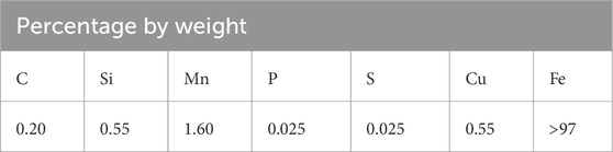
Table 1. Chemical composition of the S355J2 steel.
To conduct the study, it is proposed to use specimens with working surfaces of the following types:
• Control specimens - parallelepiped specimens without nanolaminate coating with a welded joint in the center of the specimen. The test results of such specimens will be the basis for comparative analysis to determine the effect of nanolaminates on the corrosion resistance of wind turbine materials.
• Fully coated with a metal nanolaminate coating with an outer layer of nickel or copper (BM-Ni and BM-Ni-Cu). The study of the corrosion behavior of such samples will provide information on the corrosion resistance of the nanolaminate coating (Figure 1).
• Partially coated with a nanolaminate coating with an outer layer of nickel or copper (Bound-Ni and Bound-Cu). The study of the corrosion behavior of such samples will make it possible to determine the degree of intensification of the corrosion processes due to the formation of a galvanic pair “base metal - nanolaminate” (Figure 1).

Figure 1. Positioning the working electrode area on the different types of specimens (a) and general view of clamp on cell (b).
A single-bath electroplating process using a pulsed DC method was employed to coat the sample with a Cu/Ni nanolaminate (Brunow et al., 2022). The electrolyte used was a Cu/Ni citrate bath (Bonhote and Landolt, 1997), with an average current density of 0.4 mA/cm2 for Cu deposition and 50 mA/cm2 for Ni deposition. The pulse duration for Ni and Cu deposition was 5 s and 320 s, respectively, with a 1-s pause between current pulses. The deposited coating had a total thickness of approximately 7.5 μm and consisted of a 1-μm-thick Ni base layer and 160 Cu/Ni layers with thicknesses of 39 nm and 47 nm, respectively. The thickness of the individual layers was measured by elemental mapping using Cu-K and Ni-K X-rays (8.04 and 7.47 keV). The use of a nickel base layer was found to be important for two reasons. The insufficiency of adhesion between copper and steel was resolved by using a nickel base layer for the joint. Additionally, the electrodeposition of nickel had a leveling effect on the surface roughness, as reported by Brunow et al. (2022).
3.1 Electrochemical tests technique
For electrochemical testing three tests were used:
• Open Circuit Potential (OCP) Test. This test provides information about the tendency of the material to corrode or remain passive. This test also shows when the system reaches a stable state, which is a prerequisite for the correct conduct of further electrochemical tests.
• Potentiodynamic Polarization Test. This is one of the most common tests for determining information about corrosion rate, evaluation of passivity and corrosion mechanism investigations;
• Electrochemical Impedance Spectroscopy. This test allows to calculate polarization resistance and obtain valuable information about corrosion products layers as well as about protective coatings.
The analysis of the test results will allow us to better understand the nature of corrosion processes, and the electrochemical parameters obtained will be used as input data for numerical modelling.
The electrodes had a working surface area of 0.2 and 0.5 cm2, and the scan rate was 0.25 and 0.166 mV/s for tests in 3.5% NaCl solution and tap water, respectively. During the NaCl experiments, the effect of scan rate was observed. Therefore, to ensure that the influence of the scan rate was eliminated in the next experiment, it was reduced from 0.25 mV/s to 0.1666 mV/s. The frequency range for EIS tests in the 3.5% NaCl was 19,900–2∙10–3 Hz; in the tap water EIS frequency range was 19,900–10–3 Hz. An Ag/AgCl electrode was used as a reference electrode, and electrochemical studies were performed using a Gamry Interface 1010B potentiostat. Before the electrochemical studies, the working surface was cleaned with acetone. The electrode’s working surface was located at the boundary between the nanolamination and the base metal (BM) for partially laminated samples. The working surface area was divided into two sections: one laminated and the other left unlaminated. Two techniques were used for building work electrochemical cells: isolation of specimen surface by nail polish layer and using a clamp-on electrochemical cell (Figure 1b).
When isolating the specimen surface with a nail polish layer, there are benefits such as the freedom to choose any shape for the working electrode and easily create a model of defect groups to simulate their interaction. However, it also comes with drawbacks including a long preparation time (6–12 h), the risk of crevice corrosion after 5–6 h in solution, and the need for a new coating for each test. Constructing a clamp-on electrochemical cell offers advantages like reusability, quick installation time (5–10 min), and no requirement to isolate all specimen surfaces or risk crevice corrosion. For modeling corrosion coating defects of different sizes, it is proposed to use cells with a working zone diameter of 3; 5; and 8 mm. Nonetheless, there are disadvantages such as consistently having a similar area and form for the working electrode, needing to build a new cell to change these parameters, potential aeration problems (especially for defects less than 3 mm), and difficulty in installation on the back side of samples with less than 6–7 mm thickness.
To obtain electrochemical parameters such as corrosion current icor, cathode and anode slopes (bc and ba) Tafel Extrapolation tool in Originlab Origin was used. Each electrochemical test was repeated three times. The standard deviation (SD) of parameters, calculated based on the potentiodynamic tests ranged from 5% to 8%. For the clamp-on cell, each test was performed with a fresh working electrode area. Isolation of the specimen’s surface with nail polish was used only to perform OCP tests. All other electrochemical tests were conducted using a clamp-on electrochemical cell.
4 Results and discussion
4.1 The results of the OCP tests
When analyzing the kinetics of electrode potential in a 3.5% NaCl solution, it becomes evident that stability is reached after approximately 4 hours, as shown in Figure 1a. To better understand the imperfections in the nanolayers and the interaction between nickel and copper layers, the electrode potential kinetics of a copper wire were also studied. The open circuit potential (OCP) of a nanolaminate with a copper outer layer and that of a stranded copper wire differed significantly by 0.291 V. This difference indicates that microdefects and pores in the outer copper layer allow interaction with the underlying nickel layer, influencing the electrochemical behavior of the material (Figure 2).
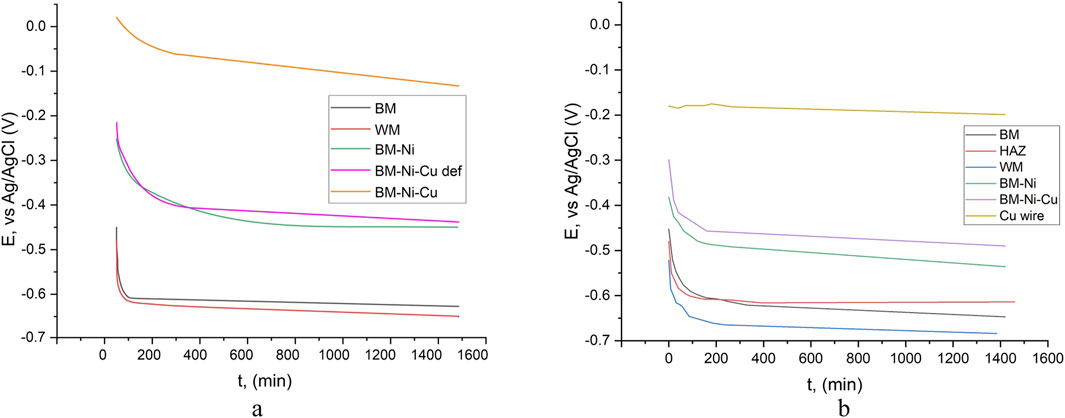
Figure 2. OCP kinetics in tap water (a) and 3.5% NaCl (b): BM-base metal, WM – welded metal, BM-Ni – specimen with nickel lamination, BM-Ni-Cu – specimen with Ni-Cu lamination, outer layer – Cu.
The lowest electrode potential was recorded for the weld metal, which contradicts expectations based on literature data suggesting that the heat-affected zone (HAZ) would exhibit the lowest potential. At the start of the experiment, the OCP of HAZ was 0.027 V lower than that of the base metal (BM), but by the end, it had increased to 0.033 V higher. The weld metal, however, consistently showed the lowest OCP values, measuring 0.037 V lower than BM and 0.070 V lower than HAZ at the end of the experiment. Such variations indicate a potential risk of galvanic corrosion, especially in cases where defects exist in the corrosion-protective coating.
OCP measurements were also conducted in tap water for control samples (BM and WM) and nanolaminated specimens, as shown in Figure 1b. The highest OCP values were recorded for BM-Ni-Cu nanolaminates, which was expected given the presence of a copper outer layer. However, repeated tests revealed that in some areas, significantly lower OCP values were recorded, with potential kinetics resembling those of BM-Ni samples. This suggests the presence of through-defects in the copper nanolayer, allowing direct electrochemical interaction with the underlying nickel. Such an assumption explains the observed variations in OCP kinetics.
For the welded joint in tap water, the kinetics of the electrode potential of the base metal and weld metal were nearly identical, with a constant potential difference throughout the experiment. A comparison of electrode potential kinetics in 3.5% NaCl solution and tap water shows that, for all specimens, OCP values in tap water were consistently higher than those in the NaCl solution. This difference was particularly pronounced for nanolaminated samples. In the NaCl medium, chloride ions likely penetrate through defects in the copper nanolayer, facilitating electrochemical interaction with the nickel layer. In contrast, such aggressive penetration does not occur in tap water, which results in OCP values and kinetics similar to those of copper wire in 3.5% NaCl solution. This hypothesis is further supported by the observed potential difference of approximately 0.1 V, which aligns with general electrochemical behavior trends for similar materials. The OCP test results are consistent with existing literature, particularly findings reported by (Matsukawa et al. 2010; Borko et al., 2019), further validating these conclusions.
4.2 Results of the potentiodynamic tests of the non-laminated (control) specimens
Potentiodynamic tests of samples with nanolaminate coatings of control samples, made from steel S355J2 (BM and WM) were performed. For base metal and welded joint, with the same exposure time, almost equal Ecor and icor values of the same level were recorded (Figure 3). Comparing the Ecor and icor values for the BM samples, the Ecor increased and the icor decreased slightly at an exposure time of 24 and 72 h (Figure 3). After an exposure time of 54 h icorr is slightly lower than after 24 h. And after 72 h icor has the lowest value. However, for all exposure times, icorr values are very close (Table 2).
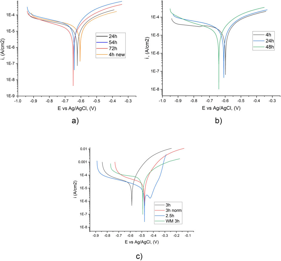
Figure 3. Potentiodynamic kinetics of BM (a) and WM (b) after different exposure times in tap water (a, b) and in 3.5% NaCl (b, c) (back and orange line – one specimen, red and blue line – another specimen).
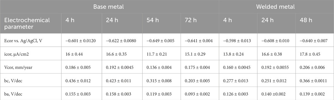
Table 2. Electrochemical characteristics for BM and WM in tap water after different exposure time.
For specimens with WM working surface potentiodynamic kinetics is quite similar to BM specimens. The corrosion potential shift between 24 h and 48 h of exposure for WM is 0.04 V, at the same time for BM it is only 0.018 V.
For WM specimens in the tap water there are no bends on the anodic branch for all exposure times (Figure 3b); instead, in 3.5% NaCl bends are observed (Figure 3c). Possible reason for the observed bends–corrosion product layer formation. But after 3 h of exposure in NaCl solution kinetics changes to monotonic (without bends) and corrosion current is up to 10 times higher. On the cathodic branch bends points are observed only for the specimen with the lowest exposure time (4 h).
Comparing the values of the corrosion current (icor) in tap water and a 3.5% NaCl solution reveals higher values in the latter. It was expected, due to the high corrosion activity of chlorides and the more than 100 times higher electrical conductivity of 3.5% NaCl solution. But values of corrosion potential shows, that in tap water its values are lower or equal to values in the 3.5% NaCl solution (Supplementary Table S3).
The potential is an integral characteristic, and lower potential shows a higher activity of metals and alloys and a higher risk of corrosion.
4.3 Results of the potentiodynamic tests of nanolaminated specimens
At the next experimental step, potentiodynamic tests of nanolaminated specimens were performed. For BM-Ni laminated specimens corrosion potential after 3 h of immersion, was about 0.05 V higher in tap water than in 3.5% NaCl solution (Figure 4). The difference in corrosion current values between the immersion time of 3 and 24 h is quite low, but a decrease in corrosion potential signals the development of the corrosion process. Comparing corrosion potentials in the same corrosive media, in tap water, the difference between Ecor for 4 h and 24 h of immersion was about 0.1 V, in the 3.5% NaCl solution same difference is after 220 and 300 min of immersion.
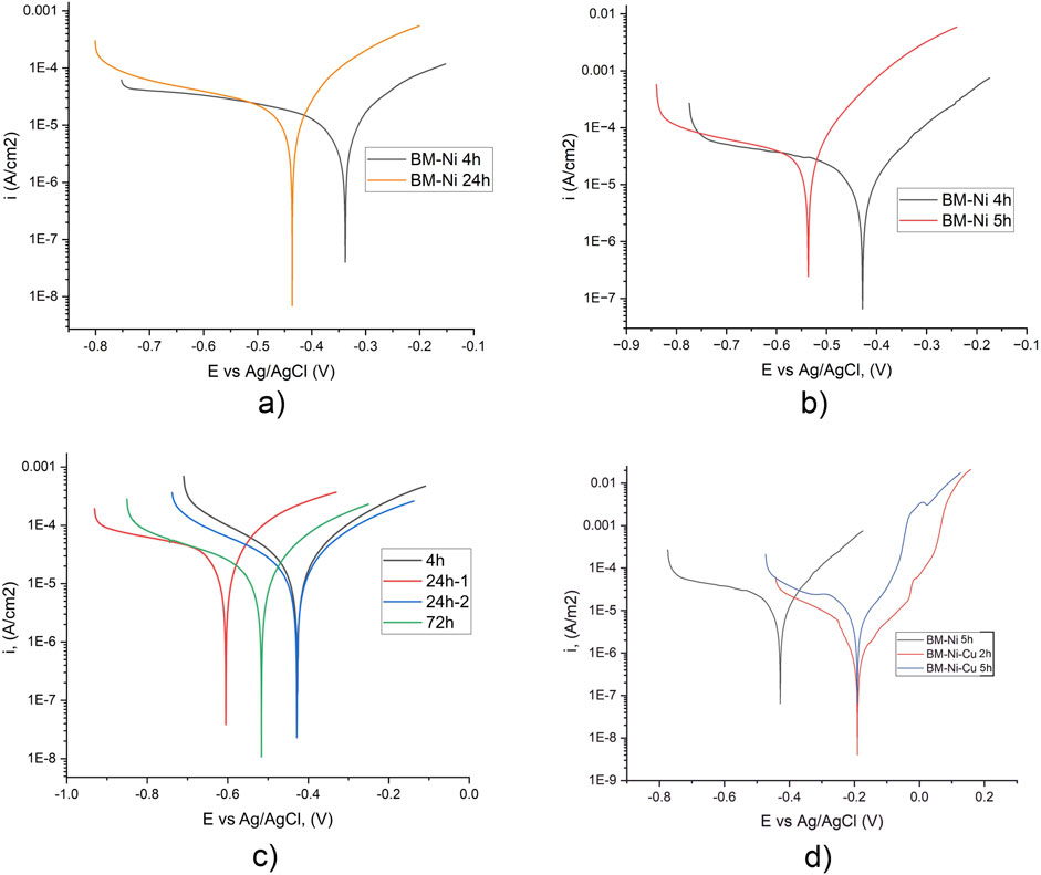
Figure 4. Potentiodynamic kinetics of specimens with BM-Ni (a, b, d) and BM-Ni-Cu (c, d) lamination in tap water (a, c) and 3.5% NaCl (b, d) after different exposure time.
Corrosion currents for BM-Ni laminated specimens in tap water are two times lower than in 3.5% NaCl solution (Figure 4; Table 3). No bends corresponding to the formation of corrosion products were recorded on the cathode branch in tap water, while in NaCl solution, insignificant bends were recorded for the sample after 220 min of immersion (Poberezhnyi et al., 2024). The results obtained are in good agreement with the data in the paper (Alves and Heubner, 2016).
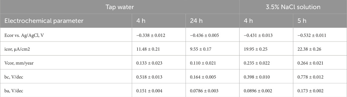
Table 3. Electrochemical characteristics for BM-Ni lamination after different exposure time.
Potentiodynamic tests of BM-Ni-Cu laminated specimens (Figure 4c) in tap water show the same electrochemical behavior for all exposures. During experiments, one specimen shows an unexpected shift of corrosion potential (curve 24 h-1), which can be explained by defects in nanolaminate coatings. After 72 h in tap water corrosion potential is about 0.1 V lower (Tables 4, 5).
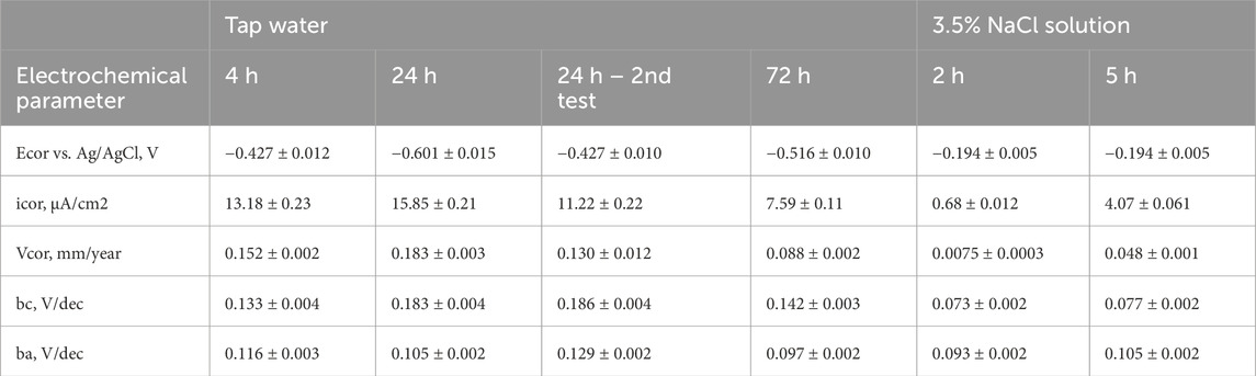
Table 4. Electrochemical characteristics for BM-Ni-Cu lamination in tap water and 3.5% NaCl solution after different exposure time (from potentiodynamic data).
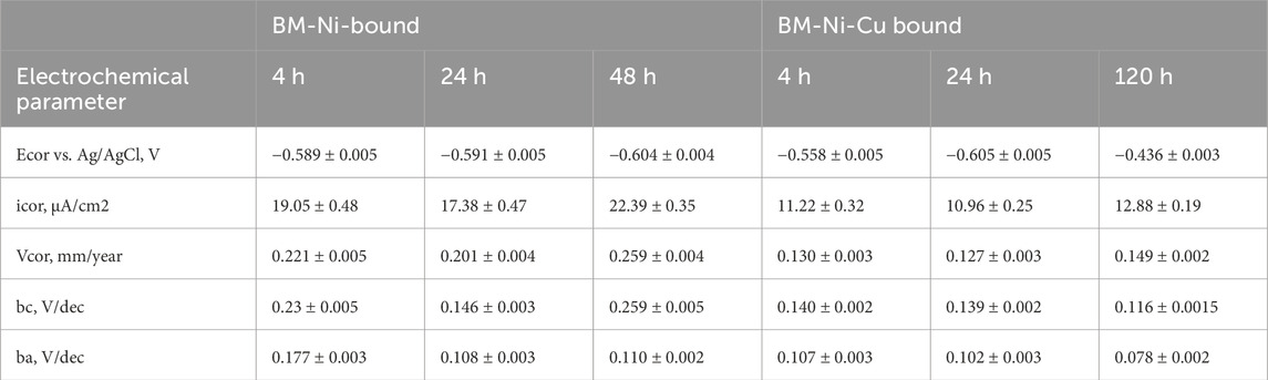
Table 5. Electrochemical characteristics for BM-Ni and BM-Ni-Cu boundary in tap water after different exposure time (from potentiodynamic data).
Potentiodynamic curves of BM-Ni and BM-Ni-Cu samples in 3.5% NaCl solution show some differences (Figure 4). On the anodic branch obtained for BM-Ni-Cu samples, bends corresponding to the formation of corrosion products are observed. Initially, they were recorded after 2 h of exposure to a corrosive environment.
During the second test after 5 h of exposure, they became even more pronounced. No bends corresponding to the formation of corrosion products were observed on the anode branch for BM-Ni samples at a similar exposure time. For both types of laminated samples, the corrosion rate increases with increasing exposure time from 2 to 5 h (Poberezhnyi et al., 2024).
Corrosion current values in tap water are lower than in 3.5% NaCl, but they are not significantly influenced by immersion time and are very close, in opposite to corrosion currents in 3.5% NaCl, which grow about 5 times between 2 h and 5 h of immersion (Table 4). Such electrochemical behavior is in good agreement with the existing literature (Feng et al., 1996; Becker, 2002; Pekchonen et al., 2002). Another difference between electrochemical behavior is the absence of bends on the anode branch in tap water, indicating that the formation of a corrosion products layer in tap water is not so intense.
Summarizing the interim conclusions, it can be stated that metal nanolaminate coatings, except BM-Ni-Cu in tap water, showed better corrosion resistance than in 3.5% NaCl solution, which is confirmed by lower corrosion currents. Such unexpected corrosion behavior of BM-Ni-Cu nanocoatings can be explained by the presence of through defects in the outer nanolayer and its interaction with the nickel nanolayer and requires further research. The values of OCP and corrosion potential in tap water are higher than in 3.5% NaCl, which indicates a lower intensity of corrosion development.
4.4 Results of the potentiodynamic tests for specimens with the working area on the boundary “base metal-nanolamination”
Potentiodynamic tests of the partially laminated specimens in tap water were performed with different exposure times (Table 5). This test is very important because metal nanocoatings are planned to be used as a surface treatment to improve fatigue and corrosion resistance characteristics.
For specimens with working surfaces located on the BM-Ni boundary, corrosion potential is stable in the immersion time range of 3–24 h. A comparison of the corrosion potential values in tap water and 3.5% NaCl solution shows a shift towards positive values, which corresponds to existing literature (Matsukawa et al., 2010).
Corrosion potential depends on the immersion time for specimens with working surface located on the BM-Cu boundary. Between 6 h and 24 h immersion time, it shifts toward negative values by 0.05 V, and between 24 h and 48 h of immersion in tap water, it shifts backward by 0.03 V. A possible explanation is corrosion processes development in the first 24 h and working surface passivation by corrosion products in the next 24 h. Another explanation–is the different surface defects on the working surface during the measurements. Corrosion current values increase with immersion time, so both explanations of corrosion potential differences are possible. The obtained results correspond to the literature (Feng et al., 1996; Becker, 2002; Pehkonen et al., 2002).
Results of potential-dynamic tests of partially nanolaminated samples with a working surface containing a “base metal-nanolayer boundary” (Supplementary Table S9) show a shift of the corrosion potential to more negative values than fully laminated specimens. This is because half of the working surface is a base metal surface with more negative potential than the laminated area. After 20 h of exposure in 3.5% NaCl corrosion rate for Ni-Cu laminated specimen is about 50% higher than for Ni-laminated, due to the greater potential difference between base metal and copper nanolayer (Poberezhnyi et al., 2024). In the future, it would be interesting to investigate the corrosion behavior at the metal-nanocoating interface at a longer exposure to a corrosive environment, as well as in the presence of cathodic protection. The results of potentiodynamic tests of samples with a working area located at the BM-nanolaminate boundary in tap water indicate high risks of galvanic corrosion in the presence of defects/imperfections in the corrosion-protective coating in the welded joint area.
Thus, electrochemical tests of the base metal and welded joints of the material of wind turbine towers were carried out. It is shown that nanolaminate coatings increase the corrosion resistance of welded joints of wind power plants. Based on the results of potentiodynamic tests, corrosion currents and corrosion rates were calculated for the base metal, welded joint, and the studied nanolaminates in 3.5% NaCl (simulated seawater) and tap water. Nanolaminate metal coatings have demonstrated good corrosion resistance, and their use to improve the operating characteristics of welded joints is promising. Electrochemical studies showed that the weakness of such coatings is the increased risk of localized corrosion along the “BM-nanolaminate” boundary.
4.5 Results of the EIS tests for nonlaminated (control) specimens
To investigate the corrosion resistance of welded joints and study the effect of nanolaminates on their characteristics, it is important to investigate the processes of surface passivation and the formation of corrosion product films. For this purpose, a series of EIS tests with different exposure times was performed, which provides additional information on the stability of the corrosion product layer under prolonged environmental exposure and assesses the corrosion resistance of the tested material.
EIS tests of the BM specimens in tap were performed after exposure time 3–72 h (Figure 5a). After 3 h of exposure, the system is almost stable, the Rp value slightly depends on the immersion time, but after 72 h electrolyte resistance (Rs) was 2 times lower than after 24 h (Supplementary Table S10).
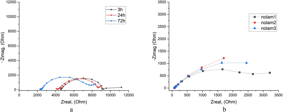
Figure 5. EIS results for BM in tap water (a) and in 3.5% NaCl solution (b) after different exposure times.
The results of the EIS test in 3.5% NaCl solution show that the Rp value is approximately 30% lower than in tap water (Figure 10b). This indicates that the corrosion resistance of the base metal in 3.5% NaCl solution is reduced compared to tap water, which is in good agreement with the results of the potentiodynamic tests (Supplementary Table S10).
EIS test of WM in tap water showed, that after 3 h of exposure system was unstable, but the repeat test showed a more stable system (Figure 6; Supplementary Table S11). Also, in the repeat test electrolyte resistance Rs was about 25%–30% higher. Comparison results in tap water and 3.5% NaCl solution shows that in 3.5% NaCl system access stability after 3 h of exposure and after 18 h of exposure its parameters are still the same (Figure 6c). Polarization resistance Rp in tap water is about 50% higher, which shows better corrosion resistance of the WM (Supplementary Table S11).
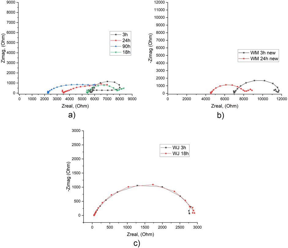
Figure 6. EIS results for WM in tap water after different exposure times: first experiment (a) and second experiment (b) and in 3.5% NaCl solution (c).
4.6 Results of the EIS tests for nanolaminated specimens
Results of the EIS test of nanolaminated specimens in tap water show significantly higher than in 3.5% NaCl solution Rp values. For BM-Ni specimens after 3 h of exposure, it is about 3 times higher, after 24 h–about 10 times higher (Figure 7; Supplementary Table S12). Such results approve higher corrosion resistance of BM-Ni specimens in tap water.
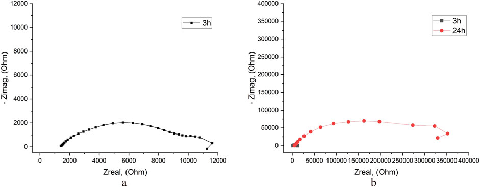
Figure 7. EIS results for specimens with BM-Ni lamination in tap water after exposure of 3 h (a, b) and 24 h (b).
For BM-Ni-Cu laminated specimens results of the EIS tests in tap water were a bit controversial. During the first experiment, two types of results (Figures 8a, b) were observed. “Normal” behavior in EIS test (Figure 8a) is in good agreement with the existing literature (Feng et al., 1996), “abnormal” behavior when Rp was about 10 times higher with the same experimental procedure and initial conditions. Such extremely high Rp values correspond to very high corrosion resistance (Supplementary Table S13). However the potentiodynamic tests did not show big differences in corrosion currents.
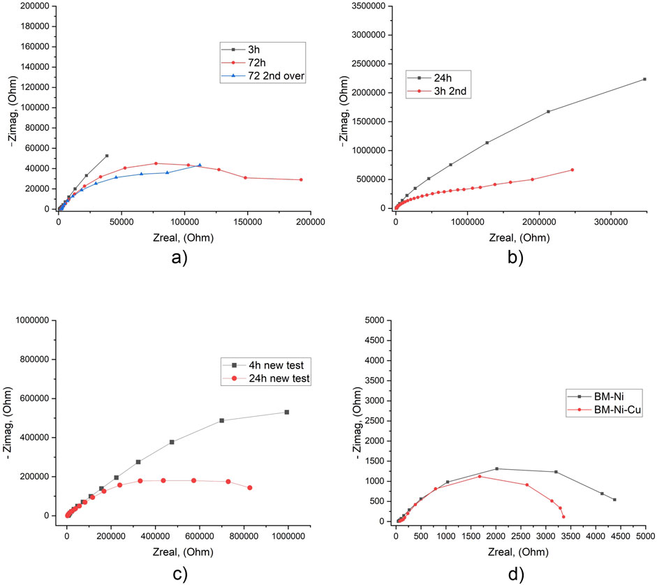
Figure 8. EIS results for specimens with BM-Ni-Cu lamination in tap water after different exposure times [normal (a), abnormal (b), second experiment (c)] and 3.5 NaCl solution (d) after 20 h of exposure.
During the second EIS experiment obtained data again showed “abnormal” behavior of BM-Ni-Cu nanolaminated specimens. This behavior may be attributed to the presence of through-thickness defects in the outer layer of the nanolaminate.
For better understanding and explanation of these results need to perform a third round of tests. Comparison of EIS results for “normal” BM-Ni-Cu laminated specimens in tap water and 3.5% NaCl solution shows significant (about 8 times) growth of Rp, and respectively, corrosion resistance (Figure 8).
4.7 Results of the EIS tests for specimens with working area on the boundary “base metal-nanolamination”
EIS test results show very close Rp values for both types of specimens (Figure 9; Supplementary Table S14). In the tap water, Rp are in the range of 3–4 kOhm; for 3.5% NaCl solution – 1.3–1.6 kOhm. This means that corrosion resistance in tap water is about 2.5 times higher. On the other hand, the results show that the type of lamination does not significantly affect the corrosion characteristics near the BM-nanolaminate boundary.
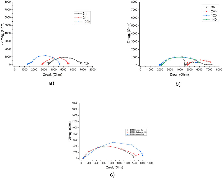
Figure 9. EIS results in tap water (a, b) and in 3.5% NaCl solution (c) for specimens with the working surface on the “BM-Ni” boundary (a, c) and “BM-Ni-Cu” boundary (b, c) after different exposure times.
Testing of the control samples showed that the polarization resistance of the base metal remained virtually unchanged for the first 24 h, and after 72 h it increased by up to 30%. For the weld metal, the situation is reversed: after 24 h of exposure, the polarization resistance decreases, which indicates an increased risk of corrosion and is in good agreement with the results of other tests.
The test results of the nanolaminated samples showed an increase in polarization resistance with increasing exposure time, which confirms their high corrosion resistance. The increase in polarization resistance for BM-Ni samples is up to 42 times, for BM-Ni-Cu samples - from 1.3 to 7 times. At the same time, the polarization resistance of BM-Ni-Cu after 4 h of exposure is 15 times higher than that of BM-Ni, and after 24 h of exposure it is 3 times higher. It should be noted separately the presence of “defective” BM-Ni-Cu samples, the polarization resistance of which after 24 h of exposure is 2 times lower than that of BM-Ni.
The corrosion of welded joints with multilayer metal nanocoatings in tap water and 3.5% NaCl was studied, and the polarization resistance of structural parts of the welded joint and samples with BM-Ni and BM-Ni-Cu nanolaminate coatings were calculated. The obtained results make it possible to assess the corrosion resistance of welded joints of the material of wind turbine towers. It is shown that nanolaminate coatings demonstrate increased corrosion resistance in both environments, which corresponds well to the previously obtained data from potentiodynamic tests. The nanolaminate coatings showed the best results in the tap water environment, where the polarization resistance values for the nanolaminated surface are often ten times higher than those for the base metal and welded joint.
4.8 Corroded surface examination with a microscope
Upon examination of the samples in the base metal zone following exposure to tap water for 24 h, it becomes evident that corrosion is relatively uniform in distribution. However, localized corrosion processes are observed to occur near the distribution surface. Additionally, damage localization is also present inside the working surface, albeit to a much lesser extent. A comparison of the appearance of the corroded surfaces after 24 h of exposure to a 3.5% NaCl solution and tap water is presented below. In the latter case, we observe a much smaller number of localized corrosion damages. This is likely due to the absence of chloride ions in tap water, which are known to cause the destruction of passive films and activate the occurrence and development of localized corrosion damage. Furthermore, the total amount of surface damage is also significantly lower in tap water (Figure 10).
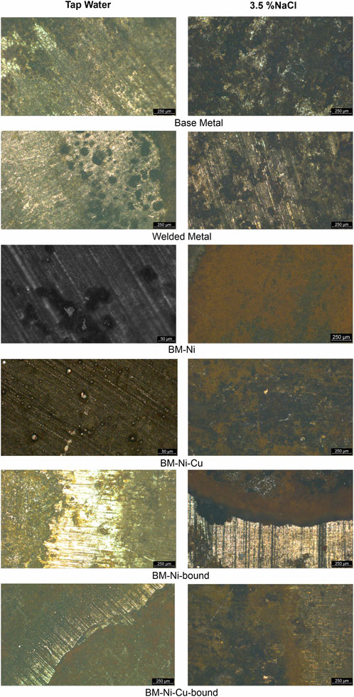
Figure 10. Corroded surface of control and nanolaminaned specimens in tap water and 3.5% NaCl solution.
Significant corrosion damage was observed on the surface of the welded joint samples after aging in both corrosive environments. In the tap water environment, a significant localization of corrosion processes can be noted both near the «corroded-uncorroded surface » boundary and inside the working area. In both cases, localized corrosion damages have a rounded shape, but on the surface of the working part, the number of corrosion damages is greater, and their size is smaller. This is visible when comparing the images of the surface at different magnifications. Also, along the corroded surface-uncorroded surface interface, we recorded the development of elongated ulcer corrosion defects. This behavior indicates an increased risk of localized corrosion in the areas of protective coating defects along the «defect-original coating » boundary.
A significant localization of corrosion processes is also observed on the surface of the samples after exposure to 3.5% NaCl solution, but the nature of the corrosion damages is somewhat different. Pitting corrosion along the «corroded-metal-uncorroded metal interface» is practically not observed. Inside the working area, as in the case of corrosion in the tap water environment, there is a significant number of localized corrosion damages. However, their shape is not round, but more elongated and they are collected in agglomerations of 5 … 20 defects. It is also necessary to note their greater depth compared to defects in tap water. These features of welded joint corrosion indicate the risk of deep corrosion defects that can become crack nucleation points.
Examination of the corroded surface of the samples with nickel nanolaminate coating (BM-Ni) after exposure to tap water showed the presence of a significant number of small, localized corrosion damages. Such damage develops mainly in places of point defects in the nanolaminate coating. At the bottom of local defects, a network of microcracks was recorded, indicating a high risk of their further growth in depth. During long-term operation, localized damage may develop and transform into penetrating damage for two layers of the nanolaminate. Penetrating damage to the outer layer of the nanolaminate was recorded, which explains the shift of the OCP under prolonged exposure to tap water. The photo also shows that local crack-like defects have formed and are developing at the bottom of the defect, on the surface of the next nanolayer.
Examination of the corroded surface in 3.5% NaCl after potentiodynamic tests showed a significant number of localized corrosion defects of rounded shape on the laminated part of the sample. On the base metal side, the corrosion is more uniform. In general, the BM-Ni nanolaminate coating demonstrates good corrosion resistance in tap water and an average resistance in 3.5% NaCl, which is confirmed by the results of EIS and potentiodynamic tests and can be used to improve the performance of welded joints of metal structures, provided that the integrity of the anti-corrosion coating is maintained.
Examination of the corroded surface of the samples with nickel nanolaminate coating (BM-Ni) after exposure to tap water showed the presence of a significant number of small, localized corrosion damages. Such damage develops mainly in places of point defects in the nanolaminate coating. At the bottom of local defects, a network of microcracks was recorded, indicating a high risk of their further growth in depth. During long-term operation, localized damage may develop and transform into penetrating damage for two layers of the nanolaminate. Penetrating damage to the outer layer of the nanolaminate was recorded, which explains the shift of the OCP under prolonged exposure to tap water. The photo also shows that local crack-like defects have formed and are developing at the bottom of the defect, on the surface of the next nanolayer. Examination of the corroded surface in 3.5% NaCl after potentiodynamic tests showed a significant number of localized corrosion defects of rounded shape on the laminated part of the sample. On the base metal side, the corrosion is more uniform. In general, the BM-Ni nanolaminate coating demonstrates good corrosion resistance in tap water and an average resistance in 3.5% NaCl, which is confirmed by the results of EIS and potentiodynamic tests and can be used to improve the performance of welded joints of metal structures, provided that the integrity of the anti-corrosion coating is maintained.
The examination of the working surface of the BM-Ni-Cu sample showed that the general corrosion is very insignificant. The copper surface is quite corrosion-resistant in the tap water environment, which is confirmed by data from potentiodynamic tests and EIS measurements. Local defects, some of which are penetrating, are also observed on the surface of the copper layer of the nanolaminate. This explains the shift in the electrode potential of the BM-Ni-Cu in the direction of the OCP values for BM-Ni. The overall surface defectiveness is lower than that of BM-Ni specimens, and the size of the defects is also 1.5 … 2 times smaller. In a 3.5% NaCl solution, the BM-Ni-Cu laminated sample, like the BM-Ni laminated sample, corroded after 24 h in the air at the “base metal - nanolamination” interface. There is predominantly uniform corrosion in the working area, along with a few pitting defects that are also present.
The examination of the corroded surface on the boundary “BM-nanolaminate” after 24 h in tap water shows expected galvanic corrosion development. It is not as intense as in 3.5% NaCl solution but still valuable. Local corrosion defects concentration over the working surface in tap water is also lower. These results together with potentiodynamic and EIS test results confirm better corrosion resistance of nanolaminates in the tap water. However, the increased risk of corrosion in case of protective paint defects/imperfections is still present.
5 Conclusion
The key findings of this study, along with their broader implications, are summarized as follows:
1. The effect of metallic multilayer nanocoatings composed of nickel and copper layers on the corrosion resistance of welded joints in wind power plants was investigated using electrochemical methods. The study was conducted in tap water and a 3.5% NaCl solution.
2. Specimens with working surface located on the boundary BM-Ni and BM-Ni-Cu lamination affected by galvanic corrosion, but its intensity in tap water is less than in 3.5% NaCl solution, as confirmed by the results of electrochemical tests and visual survey of the corroded surface.
3. The BM-Ni-Cu samples recorded a significant potential difference, which may indicate the presence of an electrochemical interaction between the nanolaminate layers. This type of specimen also displayed abnormal behavior during EIS tests. It will be interesting to study this anomalous behavior in the next stages of research to find an explanation.
4. Localized corrosion defects develop in the areas of existing surface defects of the nanolaminate, some of which become through the first layer of the nanolaminate. At the bottom of the corrosion defects, optical microscopy revealed damage to the second layer of the nanolaminate. During long-term operation, this can lead to defects that pass through the nanolaminate up to the metal of the welded joint. In the future, it is necessary to theoretically and experimentally study the effect of nanolaminate layer thickness on the concentration of surface defects and corrosion resistance of the wholecoating.
5. Inspection of the surface of the laminated samples shows defects that are possible points of corrosion initiation. This is also a possible explanation for the difference in potential values due to the probability of contact of the corrosive medium with the metal under the nanolayer.
Data availability statement
The original contributions presented in the study are included in the article/Supplementary Material, further inquiries can be directed to the corresponding author.
Author contributions
LP: Conceptualization, Formal Analysis, Investigation, Methodology, Project administration, Validation, Visualization, Writing–original draft. SK: Conceptualization, Funding acquisition, Investigation, Methodology, Project administration, Supervision, Validation, Writing–review and editing, Resources.
Funding
The author(s) declare that financial support was received for the research, authorship, and/or publication of this article. This publication has been funded by the Open-Access-Publication-Fund of the Helmut-Schmidt-University/University of the Federal Armed Forces Hamburg.
Acknowledgments
The authors thank Prof. Rutner and his group for manufacturing and providing the test samples.
Conflict of interest
The authors declare that the research was conducted in the absence of any commercial or financial relationships that could be construed as a potential conflict of interest.
Generative AI statement
The author(s) declare that no Generative AI was used in the creation of this manuscript.
Publisher’s note
All claims expressed in this article are solely those of the authors and do not necessarily represent those of their affiliated organizations, or those of the publisher, the editors and the reviewers. Any product that may be evaluated in this article, or claim that may be made by its manufacturer, is not guaranteed or endorsed by the publisher.
Supplementary material
The Supplementary Material for this article can be found online at: https://www.frontiersin.org/articles/10.3389/fmats.2025.1548202/full#supplementary-material
References
Abbas, M., and Shafiee, M. (2020). An overview of maintenance management strategies for corroded steel structures in extreme marine environments. Mar. Struct. 71, 102718. doi:10.1016/j.marstruc.2020.102718
Abdeen, D. H., El Hachach, M., Koc, M., and Atieh, M. A. (2019). A review on the corrosion behaviour of nanocoatings on metallic substrates. Materials 12 (2), 210. doi:10.3390/ma12020210
Adedipe, O., Brennan, F., and Kolios, A. (2016). Review of corrosion fatigue in offshore structures: present status and challenges in the offshore wind sector. Renew. Sustain. Energy Rev. 61, 141–154. doi:10.1016/j.rser.2016.02.017
Alves, H., and Heubner, U. (2016). Aqueous corrosion of nickel and its alloys. Reference Module Mater. Sci. Mater. Eng., 1–35. doi:10.1016/B978-0-12-803581-8.10114-6
Arya, N. K., Sharma, R., Ullas, A. V., and Ji, G. (2023). Synthesis of chitosan/nickel oxide nanocomposite for corrosion prevention of copper in NaCl solution. Mater. Today Proc. 74, 225–230. doi:10.1016/j.matpr.2022.08.056
Barla, S., and Lico, E. (2022). Global wind turbine OEMs 2021 market share. Wood Mackenzie. Available online at: https://www.woodmac.com/reports/power-markets-historical-global-wind-turbine-oems-2021-market-shares-150025486/.
Becker, A. (2002). The effect of corrosion inhibitors in drinking water installations of copper. Mater. Corros. 53 (8), 560–567. doi:10.1002/1521-4176(200208)53:8<560::aid-maco560>3.0.co;2-c
Bhandari, J., Khan, F., Abbassi, R., Garaniya, V., and Ojeda, R. (2015). Modelling of pitting corrosion in marine and offshore steel structures–A technical review. J. Loss Prev. Process Industries 37, 39–62. doi:10.1016/j.jlp.2015.06.008
Bonhote, C., and Landolt, D. (1997). Microstructure of Ni- Cu multilayers electrodeposited from a citrate electrolyte. Electrochimica Acta, 42(15), 2407–2417. doi:10.1016/S0013-4686(97)82474-7
Bordbar, S., Alizadeh, M., and Hashemi, S. H. (2013). Effects of microstructure alteration on corrosion behavior of welded joint in API X70 pipeline steel. Mater. & Des. 45, 597–604. doi:10.1016/j.matdes.2012.09.051
Borko, K., Hadzima, B., and Pastorek, F. (2019). The corrosion properties of S355J2 steel welded joint in chlorides environment. Period. Polytech. Transp. Eng. 47 (4), 342–347. doi:10.3311/pptr.12111
Brijder, R., Hagen, C. H., Cortés, A., Irizar, A., Thibbotuwa, U. C., Helsen, S., et al. (2022). Review of corrosion monitoring and prognostics in offshore wind turbine structures: current status and feasible approaches. Front. Energy Res. 10, 991343. doi:10.3389/fenrg.2022.991343
Brunow, J., Gries, S., Krekeler, T., and Rutner, M. (2022). Material mechanisms of Cu/Ni nanolaminate coatings resulting in lifetime extensions of welded joints. Scr. Mater. 212, 114501. doi:10.1016/j.scriptamat.2022.114501
Brunow, J., Spalek, N., Mohammadi, F., and Rutner, M. (2023). A novel post-weld treatment using nanostructured metallic multilayer for superior fatigue strength. Sci. Rep. 13 (1), 22215. doi:10.1038/s41598-023-49192-0
Chen, H., Liu, H., and Chen, Z. (2020). Compressive strength of corroded special-shaped welded hollow spherical joints based on numerical simulation. Thin-Walled Struct. 149, 106531. doi:10.1016/j.tws.2019.106531
de Lima, D. M., Medeiros, I. D. S., dos Santos, R. B., de Medeiros Alas, L. E., and López-Yánez, P. A. (2024). Considerations for the structural design of wind turbine towers: a practical application. Struct. Des. Tall Special Build. 33, e2158. doi:10.1002/tal.2158
Deo, Y., Guha, S., Sarkar, K., Mohanta, P., Pradhan, D., and Mondal, A. (2020). Electrodeposited Ni-Cu alloy coatings on mild steel for enhanced corrosion properties. Appl. Surf. Sci. 515, 146078. doi:10.1016/j.apsusc.2020.146078
Do, Q., An, H., Wang, G., Meng, G., Wang, Y., Liu, B., et al. (2019). Effect of cupric sulfate on the microstructure and corrosion behavior of nickel-copper nanostructure coatings synthesized by pulsed electrodeposition technique. Corros. Sci. 147, 246–259. doi:10.1016/j.corsci.2018.11.017
Feng, Y., Teo, W. K., Siow, K. S., and Hsieh, A. K. (1996). The corrosion behaviour of copper in neutral tap water. Part II: determination of corrosion rates. Corros. Sci. 38 (3), 387–395. doi:10.1016/0010-938x(96)00111-4
Feng, Y., Teo, W. K., Siow, K. S., Tan, K. L., and Hsieh, A. K. (1996). The corrosion behaviour of copper in neutral tap water. Part I: corrosion mechanisms. Corros. Sci. 38 (3), 369–385. doi:10.1016/0010-938x(96)00110-2
Flachsland, C., and Levi, S. (2021). Germany’s federal climate change act. Environ. Polit. 30 (Suppl. 1), 118–140. doi:10.1080/09644016.2021.1980288
Garcia, C., Martin, F., De Tiedra, P., Blanco, Y., and Lopez, M. (2008). Pitting corrosion of welded joints of austenitic stainless steels studied by using an electrochemical minicell. Corros. Sci. 50 (4), 1184–1194. doi:10.1016/j.corsci.2007.11.028
Haagensen, P. J., and Maddox, S. J. (2013). IIW Recommendations on methods for improving the fatigue strength of welded joints: IIW-2142-110. Available online at: https://www.offshoREWind.biz/2018/02/01/gbp-72-billion-lay-in-fighting-corrosion-in-offshore-renewables/.
Igwemezie, V., Mehmanparast, A., and Kolios, A. (2019). Current trend in offshore wind energy sector and material requirements for fatigue resistance improvement in large wind turbine support structures–A review. Renew. Sustain. Energy Rev. 101, 181–196. doi:10.1016/j.rser.2018.11.002
IRENA (2024). Renewable power generation costs in 2023. Abu Dhabi: International Renewable Energy Agency.
Jacobsson, S., and Lauber, V. (2006). The politics and policy of energy system transformation—explaining the German diffusion of renewable energy technology. Energy Policy 34 (3), 256–276. doi:10.1016/j.enpol.2004.08.029
Klijnstra, J., Zhang, X., Putten, S. V. D., and Röckmann, C. (2017). “Technical risks of offshore structures,” in Aquaculture perspective of multi-use sites in the open ocean (Cham: Springer), 115–127.
Koivuluoto, H., Milanti, A., Bolelli, G., Lusvarghi, L., and Vuoristo, P. (2014). High-pressure cold-sprayed Ni and Ni-Cu coatings: improved structures and corrosion properties. J. Therm. spray Technol. 23, 98–103. doi:10.1007/s11666-013-0016-7
Lazzarin, P., Lassen, T., and Livieri, P. (2003). A notch stress intensity approach applied to fatigue life predictions of welded joints with different local toe geometry. Fatigue & Fract. Eng. Mater. & Struct. 26 (1), 49–58. doi:10.1046/j.1460-2695.2003.00586.x
Li, C., Xia, F., Ma, C., and Li, Q. (2021). Research on the corrosion behavior of Ni-SiC nanocoating prepared using a jet electrodeposition technique. J. Mater. Eng. Perform. 30 (8), 6336–6344. doi:10.1007/s11665-021-05891-1
Li, M., Wu, H., and Sun, Y. (2023). Corrosion Performance of Welded Joints for E40 Marine Steel. Metals 13(9)1528. doi:10.3390/met13091528
Liao, X., Qiang, B., Wu, J., Yao, C., Wei, X., and Li, Y. (2021). An improved life prediction model of corrosion fatigue for T-welded joint. Int. J. Fatigue 152, 106438. doi:10.1016/j.ijfatigue.2021.106438
Maruschak, P. O., Lytvynenko, Y. V., Dzyura, V. O., Bishchak, R. T., and Polutrenko, M. S. (2020). Detection of microdefects on the surfaces of corroded steel pipes. Mater. Sci. 56, 400–409. doi:10.1007/s11003-020-00443-9
Matsukawa, Y., Chuta, H., Miyashita, M., Yoshikawa, M., Miyata, Y., and Asakura, S. (2010). “Galvanic series of Seventeen metals Conventionally used in tap water with and without Flow and its comparison to that in sea water,” in Nace CORROSION (San Antonio, Texas: NACE). NACE-10051.
Melchers, R. E. (2018). Progress in developing realistic corrosion models. Struct. Infrastructure Eng. 14 (7), 843–853. doi:10.1080/15732479.2018.1436570
Momber, A. (2011). Corrosion and corrosion protection of support structures for offshore wind energy devices (OWEA). Materials and Corrosion 62 (5), 391–404. doi:10.1002/maco.201005691
Momber, A.W., and Marquardt, T.(2018). Protective coatings for offshore wind energy devices (OWEAs): a review. J Coat Technol Res 15, 13–40. doi:10.1007/s11998-017-9979-5
Muresan, L. M. (2023). Nanocomposite coatings for anti-corrosion properties of metallic substrates. Materials 16 (14), 5092. doi:10.3390/ma16145092
Musial, W., Spitsen, P., Duffy, P., Beiter, P., Shields, M., Mulas, , et al. (2023). Offshore wind market report. 2023 edition. Golden, CO (United States): National Renewable Energy Laboratory NREL. No. NREL/TP-5000-87232.
Pehkonen, S. O., Palit, A., and Zhang, X. (2002). Effect of specific water Quality parameters on copper corrosion. CORROSION 58 (2), 156–165. doi:10.5006/1.3277316
Poberezhnyi, L., Kessler, S., Rutner, M., Spalek, N., and Okipnyi, I. (2024). Prospects of using metallic nanocoatings to improve the operational characteristics of welded joints. Procedia Struct. Integr. 59, 285–291. doi:10.1016/j.prostr.2024.04.041
Pruna, A. (2019). “Nanocoatings for protection against steel corrosion,” in Nanotechnology in Eco-Efficient construction (Woodhead Publishing), 337–359. doi:10.1016/B978-0-08-102641-0.00015-3
Raghavendra, C. R., Basavarajappa, S., and Sogalad, I. (2018). Electrodeposition of Ni-nano composite coatings: a review. Inorg. Nano-Metal Chem. 48 (12), 583–598. doi:10.1080/24701556.2019.1567537
Raghavendra, C. R., Basavarajappa, S., Sogalad, I., and Kumar, S. (2021). A review on Ni based nano composite coatings. Mater. Today Proc. 39, 6–16. doi:10.1016/j.matpr.2020.04.810
Recker, L. (2024). State of the art: corrosion protection for offshore wind turbines. Educ. J. Renew. Energy Short Rev. 10, 61–66. doi:10.25974/ren_rev_2024_10
Salam Hamdy, A. (2010). Corrosion protection performance via nano-coatings technologies. Recent Pat. Mater. Sci. 3 (3), 258–267. doi:10.2174/1874464811003030258
Schmitt-Thomas, K. G., Meisel, H., and Reich, E. (1984). Beeinflussung des Schwingungsrißkorrosions-Verhaltens verschweißter Proben durch das WIG- und Plasmanachbehandlungsverfahren. Mater. Corros. 35 (7), 321–328. doi:10.1002/maco.19840350702
Schubnell, J., Eichheimer, C., Ernould, C., Maciolek, A., Rebelo-Kornmeier, J., and Farajian, M. (2020). The influence of coverage for high frequency mechanical impact treatment of different steel grades. J. Mater. Process. Technol. 277, 116437. doi:10.1016/j.jmatprotec.2019.116437
Sharma, V. B., Singh, K., Gupta, R., Joshi, A., Dubey, R., Gupta, , et al. (2020). Review of Structural Health Monitoring Techniques in Pipeline and Wind Turbine Industries. Applied System Innovation, 4(3, 59. doi:10.3390/asi4030059
Shittu, A. A., Mehmanparast, A., Shafiee, M., Kolios, A., Hart, P., and Pilario, K. (2020). Structural reliability assessment of offshore wind turbine support structures subjected to pitting corrosion-fatigue: a damage tolerance modelling approach. Wind Energy 23 (11), 2004–2026. doi:10.1002/we.2542
Shao, W., Du, X., Zhang, W., Shi, D., Zhang, J., and Tang, P.(2025). Corrosion Mechanisms, Responses, and Mitigation Strategies for Steel Piles in Offshore Wind Turbines: A Comprehensive Review. Materials and Corrosion.doi:10.1002/maco.202414781
Smith, J. (2021). Corrosion risks in wind power facilities: assessment and management strategies. Renew. Energy 168, 636–647.
Song, R., Zhang, S., He, Yi, Li, H., Fan, Yi, He, T., et al. (2021). Effect of H-MWCNTs addition on anti-corrosion performance and mechanical character of Ni-Cu/H-MWCNTs composite coatings prepared by pulse electrodeposition technique. Colloids Surfaces A Physicochem. Eng. Aspects 630, 127519. doi:10.1016/j.colsurfa.2021.127519
Sutherland, L.S. (2018). A review of impact testing on marine composite materials: Part I–Marine impacts on marine composites. Composite Structures, 188, 197–208. doi:10.1016/j.compstruct.2017.12.073
Tai, M., and Miki, C. (2012). Improvement effects of fatigue strength by burr grinding and hammer peening under variable amplitude loading. Weld. World 56, 109–117. doi:10.1007/bf03321370
Torabinejad, V., Aliofkhazraei, M., Assareh, S., Allahyarzadeh, M. H., and Rouhaghdam, A. S. (2017). Electrodeposition of Ni-Fe alloys, composites, and nano coatings–A review. J. Alloys Compd. 691, 841–859. doi:10.1016/j.jallcom.2016.08.329
Unal, O. (2016). Optimization of shot peening parameters by response surface methodology. Surf. Coatings Technol. 305, 99–109. doi:10.1016/j.surfcoat.2016.08.004
Walford, C. A. (2006). Wind turbine reliability: understanding and minimizing wind turbine operation and maintenance costs (No. SAND2006-1100). Albuquerque, NM, and Livermore, CA (United States): Sandia National Laboratories SNL.
Wei, W., Patadia, S., and Chen, R. (2020). Economic and environmental impacts of wind power deployment in China. Energy Policy 141, 111463.
Yeganeh, M., Nguyen, T. A., Rajendran, S., Kakooei, S., and Li, Y. (2020). “Corrosion protection at the nanoscale: an introduction,” in Corrosion protection at the nanoscale (Elsevier), 3–7.
Zhang, S., Wei, J., Chen, X., and Zhao, Y. (2020). China in global wind power development: Role, status and impact. Renewable and Sustainable Energy Reviews, 127, 109881.doi:10.1016/j.rser.2020.109881
Keywords: wind power facilities, welded joints, corrosion risk, metallic nanolaminate coatings, defect interaction, Multielectrode electrochemical systems
Citation: Poberezhnyi L and Kessler S (2025) Influence of metal nanocoatings on the corrosion resistance of welded joints of wind power facilities. Front. Mater. 12:1548202. doi: 10.3389/fmats.2025.1548202
Received: 19 December 2024; Accepted: 28 February 2025;
Published: 02 April 2025.
Edited by:
Bruce Pound, Exponent, United StatesReviewed by:
Pavlo Maruschak, Ternopil Ivan Pului National Technical University, UkraineMonica Florescu, Universitatea Transilvania din Brașov, Romania
Copyright © 2025 Poberezhnyi and Kessler. This is an open-access article distributed under the terms of the Creative Commons Attribution License (CC BY). The use, distribution or reproduction in other forums is permitted, provided the original author(s) and the copyright owner(s) are credited and that the original publication in this journal is cited, in accordance with accepted academic practice. No use, distribution or reproduction is permitted which does not comply with these terms.
*Correspondence: Liubomyr Poberezhnyi, cG9iZXJlemxAaHN1LWhoLmRl