 Hao Wu
 Hong-Wu Wei
- Department of Stomatology, The Fourth Affiliated Hospital of Nanchang University, Nanchang, China
The mechanical strength and stability of single taper-retained implant–abutment connections in dental implantations have not been determined. We evaluated the mechanical performance of a single taper-retained implant system with two specifications (M1 and M2, with locking diameters being 2.0 and 2.5 mm, respectively). Static and dynamic loading, torsional strength, and lateral load tests were performed. M1 and M2 samples showed significantly different (P < 0.05) static destructive powers (363.3 ± 22.32 and 583.6 ± 15.7 N, respectively). The dynamic maximum bending moment of both samples was 1276 N mm. M1 and M2 samples showed a yield torque of 114.8 ± 13.9 and 114.3 ± 6.9 N cm, a maximum yield torque of 130.0 ± 12.0 and 156.5 ± 6.6 N cm (P < 0.05), an axial pull force of 179.8 ± 19.5 and 207.4 ± 13.7 N (P < 0.05), and a lateral force of 140.2 ± 14.7 N and 238.15 ± 14.38 N (P < 0.05). No damage or fracture was observed in abutments or implants after testing. The single taper-retained implant–abutment connection showed high mechanical stability and durability, thus is a reliable replacement of the traditional screw-retained connection. Increasing the locking diameter of the abutment enhanced the mechanical strength of the connection.
1 Introduction
Dental implantation is one of the primary treatment options for partially or fully edentulous patients and has a consistently high success rate (Pjetursson et al., 2014). Traditionally, a screw-retained connection is used to secure the abutment to the implant body. However, because this design requires the use of a central screw, it is often accompanied by mechanical complications such as damage and fracture that result from screw loosening due to excessive occlusal forces. The 5-year incidence rate of complications is 3.1%–10.8% (Pjetursson et al., 2014). These complications can potentially lead to implant loss and even irreversible implant failure (Kim et al., 2021; Bischof et al., 2024).
To address the above issues, new implant–abutment connection designs have been developed that take advantage of advancements in material technology to improve mechanical stability and reduce screw-related failures. The newest designs are primarily categorized into two types: external connection and internal connection. External connection is achieved by connecting a protrusion in the implant’s upper plane with a concave area in the abutment’s lower plane. Internal connection is achieved between a concave area in the implant and a protrusion in the abutment. Internal connections are associated with a lower incidence of bone resorption and mechanical complications and are more commonly used in clinical practice (Caricasulo et al., 2018; Camps-Font et al., 2023). Conical connections, also referred to as Morse taper connections (Schmitt et al., 2014), provide a tight fit between the implant and abutment, thereby minimizing bacterial penetration and improving long-term stability (Ricomini Filho et al., 2010; do Nascimento et al., 2012; Machado et al., 2013). Popular Morse taper systems include Ankylos (5.7°), ITI (6°–8°), and Astra Tech (11°), all of which use screws for retention. In contrast, the Bicon system (1.5°) uses a screwless Morse taper connection design that relies purely on frictional engagement for retention and thus eliminates the risk of complications that arise from screw loosening or fracture (Tang et al., 2017).
While Morse taper systems show acceptable implant survival rates (Mangano et al., 2011; Urdaneta et al., 2012) and predictability and demonstrate improved convenience in clinical practice, the performance of this system is still under debate. In a previous study on dental implant restoration complications, a screwless Morse taper system was associated with high rates of restoration dislodgement in the maxillary anterior area (Urdaneta et al., 2010). This may be because of two reasons. First, the low bone density and oblique occlusal loading in this area may increase the micromovement of the implant–abutment interface. Second, restorations in the maxillary anterior area mainly experience forces that are non-axial, which can cause rotation or loosening of the abutment when the force becomes excessive. The same study also observed that Morse taper systems may have fractures in abutments with 2.0 mm locking diameters and dislodging in abutments with 3.0 mm locking diameters in the posterior areas (Urdaneta et al., 2010), likely because these areas are subject to greater chewing forces that cannot be sustained by narrow abutments. These findings suggest that the abutment diameter and loading patterns greatly affect the performance of Morse taper systems. However, clear understanding of the mechanical performance of screwless Morse taper connections remains limited because of the lack of data.
To fill this gap, we conducted in vitro tests to evaluate the mechanical strength of a screwless Morse taper implant–abutment connection system, which adopts a narrow-diameter design that was less investigated before. Compared with previous works, we included more types of tests and also greatly increased the extent of mechanical challenge in the tests. Our findings provide useful insights and references for developing more advanced implant restoration strategies.
2 Materials and methods
2.1 Sample preparation
In this study, we developed a screwless Morse taper implant–abutment system, with a connection design based on the commercial product from Bicon (Bicon Dental Implant, Boston, MA, United States). A total of 68 implants were machined using TA4G titanium alloy on a BO205-III precision lathe (Precision Tsugami Co., Kyoto, Japan) and included two types: M1 (3.3 × 11 mm; batch No.: M120230320) and M2 (3.5 × 14.5 mm; batch No.: M220230807) (Figures 1, 2). The implants (M1, M2) were made by Jiangxi Zhiyale Medical Equipment Co., Ltd. (Nanchang, Jiangxi, China). Two types of solid abutments were produced with a locking diameter of 2.0 mm (Batch No.: ZJT20221009) and 2.5 mm (Batch No.: ZJT20230814) and with the internal Morse taper angle uniformly set as 1.5° (Figures 1, 2). A semispherical force-loading cap was added on the abutment. The designs and specifications of the implant and abutments are shown in Figure 3. All implants and abutments were cleaned, polished, and inspected for precision (±0.2 mm tolerance) before inclusion.
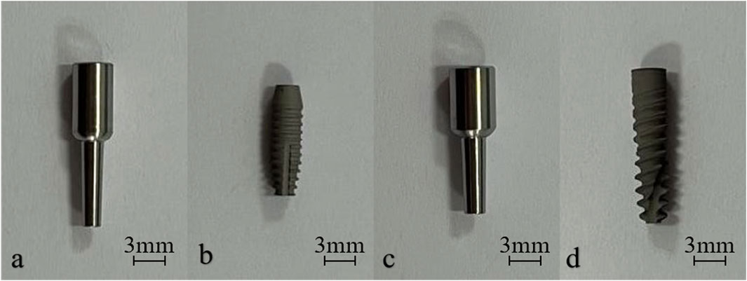
Figure 1. Photos of the abutment with 2.0-mm locking diameter (a), the M1 implant (b), the abutment with 2.5-mm locking diameter (c) and the M2 implant (d).
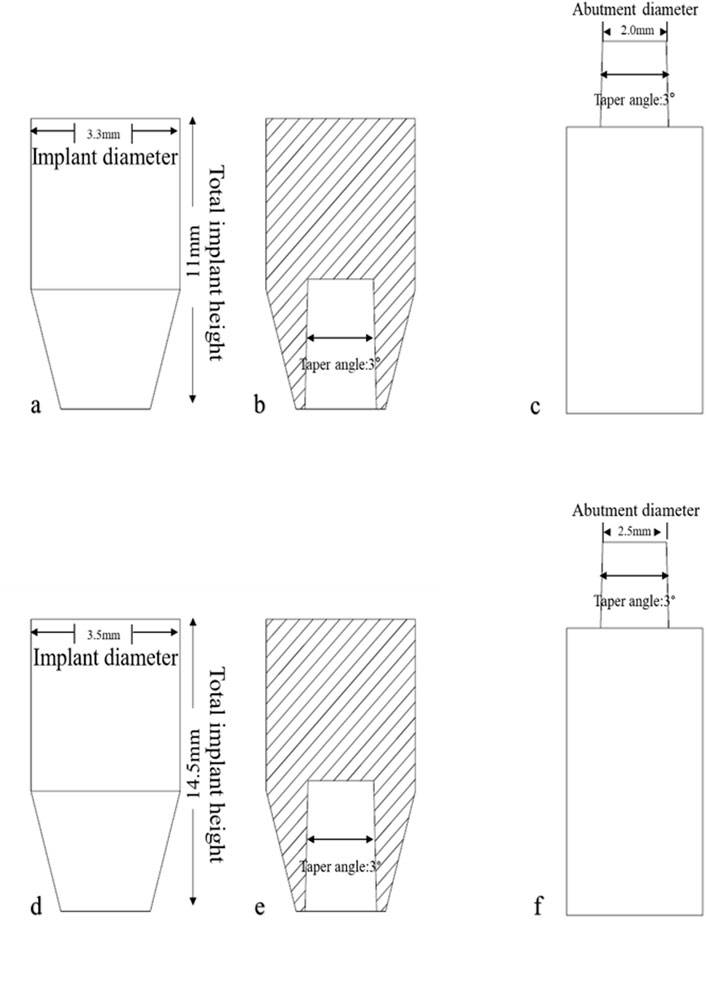
Figure 2. Designs of the implant and abutment test samples. (a, d) Front view of the M1 (a) and M2 (d) implant. (b, e) Cross-sectional view of the M1 (a) and M2 (d) implant. (c, f) Front view of the abutment with 2.0-mm (c) and 2.5-mm (f) locking diameter.
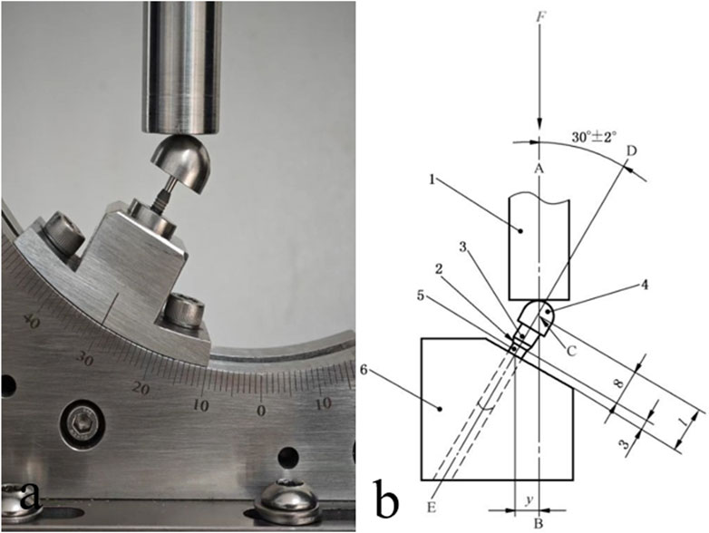
Figure 3. A photo (a) and the design (b) of the setup for static and dynamic loading tests. 1. Force loading module. 2. Nominal bone level. 3. Solid abutment. 4. Semispherical force-loading cap. 5. Implant main body. 6. Metal base.
2.2 Equipment
The CMT6104 Microcomputer Controlled Electronic Universal Testing Machine (Shanghai Xinbiao Testing Instrument Manufacturing Co., Ltd., Shanghai, China) and BX53M Optical Microscope (Olympus, Tokyo, Japan) were used in this study.
2.3 Testing procedures
All tests were conducted under constant temperature (20°C ± 10°C) and humidity (40%–60%) in a materials technology lab to simulate the physiological oral environment. The implant–abutment system samples were embedded in ASTM F1839-compliant Grade 20 polyurethane foam blocks (simulating cancellous bones; Shenzhen Biosungreen Tech Co., Ltd., Shenzhen, Guangdong, China) following the manufacturer’s instructions. Specifically, the block was pre-drilled, and the implant was screwed or tapped into the blocks; the abutment was mounted onto the implants by tapping. Then the connected implant and abutment were together removed from the block and mounted onto the universal testing machine.
For static and dynamic loading tests (n = 16), the in-bone fixation part of the test sample was embedded and fixed, with the distance from the fixation level to the nominal bone level being 3.0 ± 0.5 mm and the distance from the center of the semispherical force-loading cap (C, Figure 4) to the fixation level being l = 11.0 ± 0.5 mm.
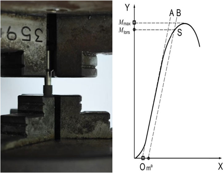
Figure 4. Setup for the torsional resistance test (left) and a representative torque vs. angular displacement curve (right).
Static loading tests involved the application of a static force load by the Universal Testing Machine to the semispherical force-loading cap at an angle of 30° to the implant’s body axis and a rate of 5 mm/min, with an upper limit force of 232 N (Figure 4). The force vs. displacement curve was monitored until the force reached maximum and began to decline, identifying the static destructive power. The sample was inspected to identify the affected part and the mode of damage was recorded, which could be material yielding, permanent deformation, or component loosening or breakage. The dynamic loading tests involved five million cycles of unidirectional force loading with an upper limit force of 232 N, a load ratio of 0.1, a sinusoidal loading waveform, and a frequency of 15 Hz. After the test was complete, the specified load force that was sustained by the test sample over five million loading cycles was recorded to calculate the corresponding bending moment, M.
For torsional resistance tests (n = 12), both ends of the test sample were fixed using the collets on the micro-controlled torsion testing machine. Torque was applied at a rate of 5°/min until the torque vs. angular displacement curve began to decline (Figure 5). The yield torque and maximum yield torque were calculated using the curve.
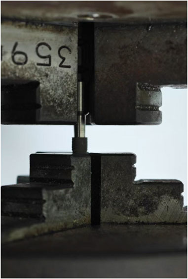
Figure 5. Setup for the axial pull-out test.
For axial pull-out tests (n = 10), the test sample and its fixing collet were stabilized at the base of the force loading module while ensuring that the longitudinal axis of the test sample was aligned with the force load to be applied. The top part of the sample was subjected to axial tensile force at a pulling rate of 5 mm/min until detachment occurred (Figure 6). The axial tensile force vs. displacement curve was recorded, and the axial pull force, i.e., the force needed to detach the implant from the abutment, was recorded.
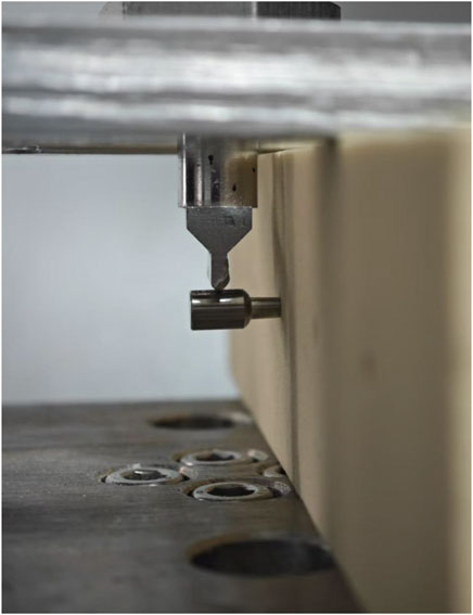
Figure 6. Setup for the lateral load test.
For lateral load tests (n = 10), the test sample was placed horizontally. A cantilever bending test was performed by applying a force perpendicular to the initial longitudinal axis of the sample at a rate of 5 mm/min until the force vs. displacement curve reached maximum and began to decline (Figure 7). The length of the moment arm, the force vs. displacement curve, and the lateral force were recorded.
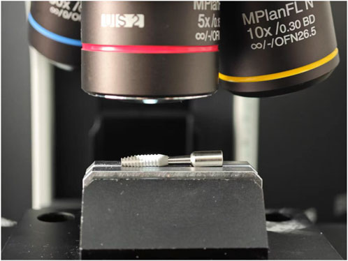
Figure 7. Setup for microscopic inspection.
For microscopic inspection (n = 20), a high-magnification optical microscope was used to observe microstructural changes at the surface of implant samples after the axial pull-out or lateral load test (Figure 8).
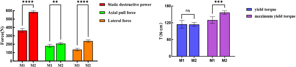
Figure 8. Statistical analysis of static test results for M1 and M2 samples. **p < 0.02; ***p < 0.01; ****p < 0.001, assessed by Student’s t-test.
2.4 Statistical analysis
G*Power v 3.1.9.7 was used to calculate statistical power for the tests and determine the appropriate sample size for each test. Data analysis was conducted using SPSS 26.0 (IBM, Armonk, NY, United States). Data with a normal distribution, as judged by the Kolmogorov–Smirnov test, are presented as mean ± standard deviation, with independent sample t-test used for data comparison. A p-value less than 0.05 indicated statistical significance.
3 Results
3.1 Static and dynamic loading tests
A significantly higher static destructive power was identified in the M2 samples than in the M1 samples (583.6 ± 15.7 vs. 363.3 ± 22.3 N), indicating better mechanical performance of the M2 samples (Table 1; Figure 9). Detailed static loading test curves are presented in Figure 10.
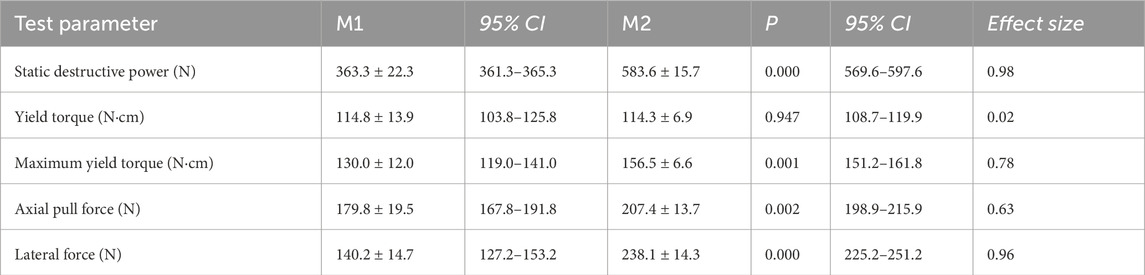
Table 1. Results of the static tests of M1 and M2 samples.
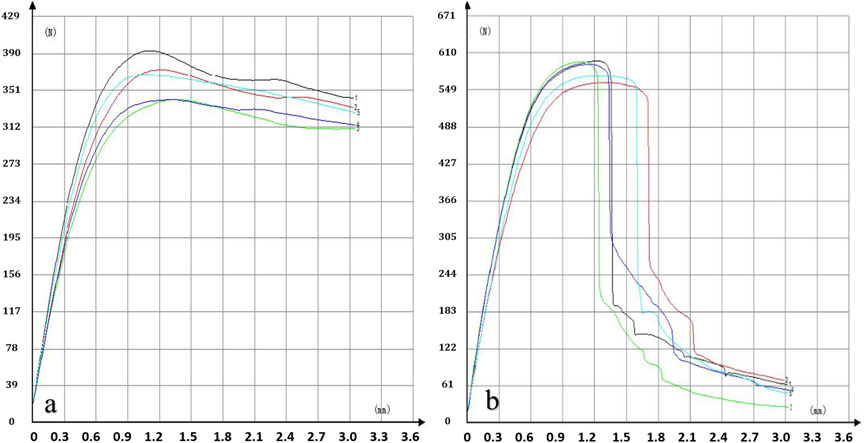
Figure 9. Static loading test curves of M1 (a) and M2 (b) samples.
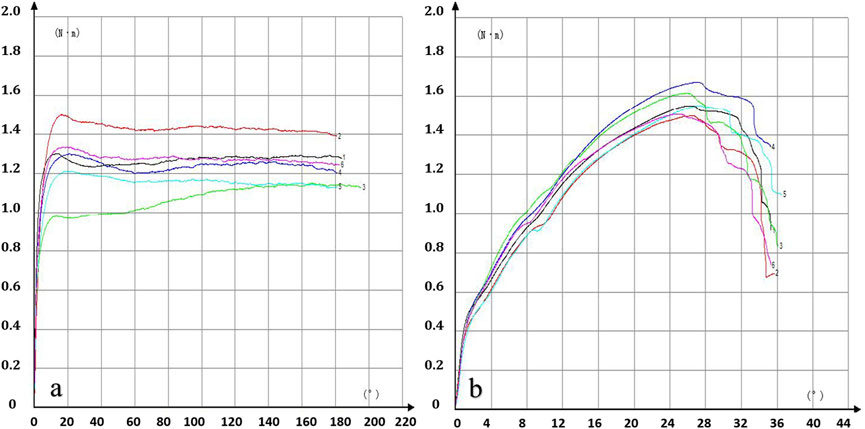
Figure 10. Torsional resistance test curves of the M1 (a) and M2 (b) samples.
All implants and abutments survived the dynamic loading test without failure, yielding an overall survival rate of 100%. The dynamic maximum bending moment was 1276 N mm for both M1 and M2 samples.
3.2 Torsional resistance test
M1 samples rendered a yield torque of 114.8 ± 13.9 N cm and a maximum yield torque of 130.0 ± 12.0. While M2 samples rendered a comparable yield torque of 114.3 ± 6.9 N cm, the maximum yield torque reached a significantly higher value of 156.5 ± 6.6 N cm (P < 0.05, Table 1; Figure 9).
The torsional resistance test curves are presented in Figure 11.
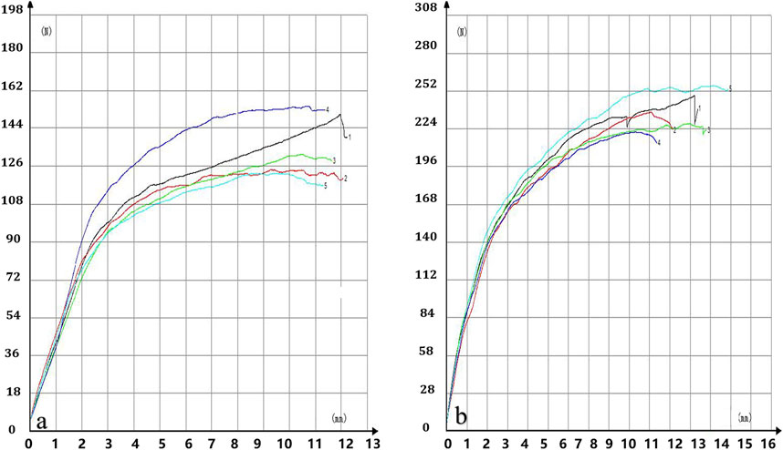
Figure 11. Lateral load test curves of the M1 (a) and M2 (b) samples.
3.3 Axial pull-out test
M1 samples rendered an axial pull force of 179.8 ± 19.5 N M2 samples rendered a significantly higher axial pull force of 207.4 ± 13.7 N (P < 0.05, Table 1).
3.4 Lateral load test
M1 samples rendered a lateral force of 140.2 ± 14.7 N M2 samples rendered a significantly higher lateral force of 238.1 ± 14.3 N (P < 0.05, Table 1).
The lateral load test curves are presented in Figure 12.
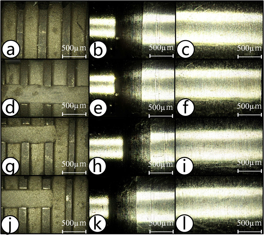
Figure 12. Post-test microscopic inspection of the implants and abutments. (a–f) Appearance of the implant and abutment for M1 (a–c) and M2 (d–f) samples before and after axial pull-out test. (g–l) The appearance of the implant and abutment for M1 (g–i) and M2 (j–l) samples before and after lateral load test.
3.5 Post-test microscopic inspection
No crack or surface damage was detected on any of the implants or abutments after completion of the axial pull-out and lateral load tests (Figure 12).
4 Discussion
By simulating the chewing motion, this study evaluated the mechanical performance of a single taper-retained dental implant–abutment system and inspected how the system is impacted by the size of the implant–abutment connection interface. The results demonstrated that the single taper-retained connection demonstrated excellent stability while producing minimal micromotion and wear under various high-stress conditions; this system should therefore help prolong the service life of the implants. These findings not only enhance the understanding of single taper-retained implant–abutment systems, but also provide useful references for clinicians and may help improve the success rate of dental implantation and patient satisfaction.
The single taper-retained connection system tested in this study involved a screwless design with an internal connection taper angle of 1.5°. Retention of this system relies entirely on the friction generated by the tight contact between the implant and the abutment. During implantation, the implant is tapped onto the abutment with external force, which produces a wedging effect at the implant–abutment interface (IAC) to achieve a tight connection—sometimes referred to as “cold welding.” This novel connection mechanism has several advantages over traditional mechanisms. First, it constrains the microgap at the coronal aspect of the IAC, which ensures superior sealing and stability, significantly reducing bacterial penetration and lowering the risk of infection (Baixe et al., 2010; Chu et al., 2012; Liu and Wang, 2017; Gao et al., 2021). Second, the abutment has a solid cylindrical structure, which has high mechanical strength, also ensuring high stability at the peri-implant bone levels and a long service life of the implants (Ribeiro et al., 2024). Finally, owing to the high-precision manufacturing of the implant–abutment interface, consistency can be ensured across implantations.
Static and dynamic loading tests are commonly used to evaluate the mechanical strength of implant–abutment connections. For instance, Dittmer et al. studied the fracture strength of Ankylos Morse taper implants by applying a 30° oblique load; the failure load was 368 N for the screw-retained connection and 430 N for the Morse taper connection (Dittmer et al., 2012). Imam et al. investigated the static load strength of narrow-diameter implant systems; the average static destructive power was 367.20 ± 98.05 and 568.80 ± 85.24 N for implants with a 3.0 mm or 3.5 mm connection diameter, respectively (Imam et al., 2014). Marchetti et al. conducted fatigue tests on implant systems with an internal hex connection of 3.8-mm diameter; the results showed that the static destructive power was 499.6 ± 50.1 N (Marchetti et al., 2014). Duan et al. conducted fatigue tests on implant systems with a 3.3 mm connection diameter; under a cyclic load of 185 N, the probability of failure after 1 × 10⁶ dynamic loading cycles was 5% (Duan et al., 2018). The study suggested that, compared with narrow-diameter implants, implants with the same connection diameter but using the Morse taper connection mechanism achieved higher static and fatigue load capacity. Notably, in our study, the static destructive powers of the M1 and M2 implants both exceeded those of the previously reported Morse taper and screw-retained connections. Furthermore, Dittmer et al. showed that the internal connection diameter of the implant has a significant influence on its overall mechanical strength (Dittmer et al., 2012), which corroborates our findings in comparing M1 and M2.
Humans can generate great bite forces (Wang, 2012; Zhou et al., 2022). Ferrario et al. reported that in healthy young adults, the occlusal force on a single tooth is between 98.33 and 306.07 N (Ferrario et al., 2004). Shoji et al. found that occlusal forces in healthy adults ranged from 86.40 to 1758.60 N, with an average of 798.33 ± 492.16 N (Shoji et al., 2022). After an implant–abutment system experiences more and more load cycles with such large forces, it is expected to have gradually declined mechanical performance (Ricciardi Coppede et al., 2009). Nonetheless, in this study, both M1 and M2 implant–abutment connections withstood 5 × 10⁶ cycles of dynamic loading at 23.2–232 N, demonstrating excellent mechanical durability.
By performing in vitro fatigue tests, Ugurel et al. found that the mechanical strength of screwless Morse taper implants with a 3° taper angle was lower than that of screw-retained implants. None of the tested screwless Morse taper implants survived 1.2 × 10⁶ cycles of dynamic loading of 120 N applied at a 30° angle; all samples failed within the first 1 × 10⁵ cycles as a result of fracture (Ugurel et al., 2015). In contrast, in the study by Bagegni et al., all tested screwless Morse taper implants survived 1 × 10⁶ cycles of dynamic loading of 100 N (Bagegni et al., 2022). The discrepancy between these two studies may be because the implants tested in the first study had a thinner internal wall. Here, our tested samples also successfully survived 5 × 10⁶ cycles of dynamic loading applied at a 30° angle, supporting the conclusion that single taper-retained connections can achieve high mechanical strength. In contrast with the results from Ugurel et al. (2015), the screwless implant samples in our study showed no surface cracks or abutment fractures after testing, consistent with Bagegni et al. (2022).
Screw loosening or fracture is the most common mechanical complication in dental implant restorations (Schwartz-Arad et al., 1999; Theoharidou et al., 2008). The likelihood of screw loosening and fracture is influenced by the design, material, and diameter of the screw, the applied torque, and the geometry of the implant–abutment connection (Gupta et al., 2015), but was reported to be considerably high across multiple studies (Goodacre et al., 1999; Pintinha et al., 2013; Hsu et al., 2018; Pjetursson et al., 2018). In our study, none of the tested implants showed abutment fracture after five million mastication-simulating load cycles, demonstrating their mechanical reliability and superiority. The main reason for screw loosening after implantation is that the dynamic load cycles during mastication may cause the vertical subsidence of the abutment, which can induce slippage between implant threads and screw threads, resulting in torque loss and screw loosening (Kim et al., 2014; Bagegni et al., 2021). We previously found that during simulated mastication, the total vertical displacement of screwless Morse taper abutments ranged from 0.20 to 0.47 mm (average: 0.32 mm), and the finger-pressed displacement ranged from 0.06 to 0.15 mm (average: 0.10 mm); the degree of subsidence was affected by the loading force, locking depth, locking diameter, and thickness of the implant’s external wall (Ren et al., 2024). Further in vitro studies are needed to determine the optimal design for related key parameters such as locking diameter and depth, so as to prevent or minimize abutment subsidence in patients.
For screw-retained implant–abutment connections, in addition to repeated screw tightening (D’Addazio et al., 2021), the geometry of the connection also affects the pull-out resistance. For instance, smaller angles were found to offer greater resistance (Caballero et al., 2024). A similar result was observed for screwless connections as well (Nogueira Barbosa Marchon et al., 2024), which is likely because of two reasons. First, a smaller taper angle leads to a greater contact area, which increases the friction at the implant–abutment interface and thus strengthens the cold welding effect (Caballero et al., 2024; Nogueira Barbosa Marchon et al., 2024). Second, Hsu et al. showed that smaller taper angles in implant–abutment connections may result in greater axial displacement, thereby increasing friction and thus the pull-out resistance (Hsu et al., 2018). Like in our work, Hsu et al. also knocked the upper component into the implant to achieve the connection, which led to pull-out resistance and mechanical stability comparable to the screw-retained connections (Hsu et al., 2018). The implants in our study use an internal taper of 1.5° with screwless solid abutments that maximize the implant–abutment contact area, ensuring adequate pull-out resistance. The satisfactory pull-out test results of these implants are strongly encouraging and indicate that alternative implant–abutment connection designs should be considered to overcome the issue of screw loosening in traditional designs. In addition, our data suggests that increasing the locking diameter and thus the frictional contact surface can also increase the axial pull force.
A higher torque in screw-based systems leads to greater preload, which reduces the risk of screw loosening and restoration dislodgement (Cibirka et al., 2001; Coelho et al., 2007). However, excessive torque beyond a threshold can create significant friction between the implant and screw threads, which can potentially lead to wrench fracture. Hyun et al. found that adding a positioning hex design to a Morse taper abutment ensures a snug fit with the implant’s corresponding hex slot, and thus can effectively increase torsional resistance (Hyun et al., 2020). However, adding a hex design to a Morse taper abutment also reduces the conical surface area of the abutment, which may compromise the biomechanical performance of the Morse taper connection. Yao et al. demonstrated that in the Cowell implant system with a 7° taper, the single taper-retained connection offered no torsional resistance. The authors found that incorporating an internal octagonal structure provided torsional resistance, but it also lowered the bending strength of the abutment (Yao et al., 2015). Farré-Berga et al. showed that with a 20° angle in the screw channel, connections in the Ball Head System and the Hexagonal Screwdriver System had a mean yield torque of 67.0 ± 12.0 and 45.0 ± 2.0 N cm, respectively (Farre-Berga et al., 2020). In our torsional resistance tests, M1 and M2 samples showed a maximum yield torque of 130.0 ± 12.0 and 156.5 ± 6.6 N cm, respectively, which were substantially higher than those reported by Farre-Berga et al. (2020), even though our abutments use no anti-torsion features. This result suggests that increasing the contact area and friction between the abutment and the implant effectively strengthens the cold welding effect, ensuring reliable torsional stability.
The performance of the implant–abutment connection plays a crucial role in the successful implantation of implant-supported fixed restorations. The abutment is connected to the implant via external or internal connection mechanisms, with the internal connection being biomechanically advantageous. Peri-implantitis and marginal bone loss are two common complications of implant-supported restorations that are induced by the gap space at the implant–abutment interface, with the former often preceding and facilitating the latter. Under repetitive lateral occlusal loading, traditional screw-retained systems, even those with an internal hex design, are prone to screw loosening, which increases the gap space at the implant–abutment interface, leading to bacterial infiltration and subsequent bone resorption, especially in jaw areas of low bone density (Gehrke et al., 2023; Angermair et al., 2024). In contrast, because of its self-locking design, the Morse taper connection offers superior lateral stability, which does not form microgaps under lateral forces (Angermair et al., 2024).
Terrats et al. studied the lateral mechanical strength of single-unit and multi-unit restorations with a narrow diameter implant; the lateral failure force was 118–230 and 488–759 N, respectively, demonstrating clearly greater lateral load resistance in the multi-unit restorations (Terrats et al., 2024). Our study showed that M1 and M2 implants had a lateral resistance of 140.2 ± 14.7 and 238.1 ± 14.3 N, respectively, which are relatively low but within clinically acceptable limits. Furthermore, comparison of the results of M1 and M2 indicates that increasing the abutment diameter enhances the implant’s fracture resistance and lateral load-bearing capacity. In anterior regions, implant restorations may endure non-axial forces 4–5 times greater than normal occlusal forces. Such lateral loading can induce micromotion and microgaps, potentially causing marginal bone resorption. Through continued design optimization (e.g., reducing the taper angle or increasing the contact area), researchers should be able to improve the lateral stability of the implant–abutment connection.
Overall, under standardized conditions, all samples tested in this work withstood fatigue loading, indicating that the single taper-retained implant–abutment connection represents a reliable option for dental restorations. Nonetheless, due to certain limitations of our work such as small sample sizes and lack of high-resolution microscopic imaging (e.g., scanning electron microscopy), as well as the fact that in vitro conditions cannot fully recapitulate the oral environment, further standardized tests are needed to more comprehensively analyze the mechanical behavior of single taper-retained implant systems.
5 Conclusion
This in vitro study demonstrated that a single taper-retained implant–abutment connection offers strong mechanical performance under both static and long-term dynamic loading conditions. Increasing the locking diameter of the abutment improves the mechanical performance of the connection.
Data availability statement
The raw data supporting the conclusion of this article will be made available by the authors, without undue reservation.
Author contributions
HW: Writing – original draft, Formal Analysis, Data curation, Conceptualization, Investigation. NC: Data curation, Investigation, Writing – review and editing. L-WC: Data curation, Investigation, Writing – review and editing. S-GG: Conceptualization, Writing – review and editing, Methodology. XZ: Writing – review and editing, Data curation, Resources. FY: Resources, Data curation, Writing – review and editing. S-BW: Writing – review and editing, Resources, Data curation. H-WW: Methodology, Project administration, Writing – review and editing.
Funding
The author(s) declare that no financial support was received for the research and/or publication of this article.
Conflict of interest
The authors declare that the research was conducted in the absence of any commercial or financial relationships that could be construed as a potential conflict of interest.
Generative AI statement
The author(s) declare that no Generative AI was used in the creation of this manuscript.
Publisher’s note
All claims expressed in this article are solely those of the authors and do not necessarily represent those of their affiliated organizations, or those of the publisher, the editors and the reviewers. Any product that may be evaluated in this article, or claim that may be made by its manufacturer, is not guaranteed or endorsed by the publisher.
References
Angermair, J., Iglhaut, G., Meyenberg, K., Wiest, W., Rack, A., Zabler, S., et al. (2024). In vitro assessment of internal implant-abutment connections with different cone angles under static loading using synchrotron-based radiation. BMC Oral Health 24, 396. doi:10.1186/s12903-024-04156-2
Bagegni, A., Weihrauch, V., Vach, K., and Kohal, R. (2022). The mechanical behavior of a screwless morse taper implant-abutment connection: an in vitro study. Mater. (Basel) 15, 3381. doi:10.3390/ma15093381
Bagegni, A., Zabler, S., Nelson, K., Rack, A., Spies, B. C., Vach, K., et al. (2021). Synchrotron-based micro computed tomography investigation of the implant-abutment fatigue-induced microgap changes. J. Mech. Behav. Biomed. Mater 116, 104330. doi:10.1016/j.jmbbm.2021.104330
Baixe, S., Fauxpoint, G., Arntz, Y., and Etienne, O. (2010). Microgap between zirconia abutments and titanium implants. Int. J. Oral Maxillofac. Implants 25, 455–460.
Bischof, F. M., Mathey, A. A., Stahli, A., Salvi, G. E., and Bragger, U. (2024). Survival and complication rates of tooth- and implant-supported restorations after an observation period up to 36 years. Clin. Oral Implants Res. 35, 1640–1654. doi:10.1111/clr.14351
Caballero, C., Rodriguez, F., Cortellari, G. C., Scarano, A., Prados-Frutos, J. C., De Aza, P. N., et al. (2024). Mechanical behavior of five different morse taper implants and abutments with different conical internal connections and angles: an in vitro experimental study. J. Funct. Biomater. 15, 177. doi:10.3390/jfb15070177
Camps-Font, O., Rubianes-Porta, L., Valmaseda-Castellon, E., Jung, R. E., Gay-Escoda, C., and Figueiredo, R. (2023). Comparison of external, internal flat-to-flat, and conical implant abutment connections for implant-supported prostheses: a systematic review and network meta-analysis of randomized clinical trials. J. Prosthet. Dent. 130, 327–340. doi:10.1016/j.prosdent.2021.09.029
Caricasulo, R., Malchiodi, L., Ghensi, P., Fantozzi, G., and Cucchi, A. (2018). The influence of implant-abutment connection to peri-implant bone loss: a systematic review and meta-analysis. Clin. Implant Dent. Relat. Res. 20, 653–664. doi:10.1111/cid.12620
Chu, C. M., Huang, H. L., Hsu, J. T., and Fuh, L. J. (2012). Influences of internal tapered abutment designs on bone stresses around a dental implant: three-dimensional finite element method with statistical evaluation. J. Periodontol. 83, 111–118. doi:10.1902/jop.2011.110087
Cibirka, R. M., Nelson, S. K., Lang, B. R., and Rueggeberg, F. A. (2001). Examination of the implant-abutment interface after fatigue testing. J. Prosthet. Dent. 85, 268–275. doi:10.1067/mpr.2001.114266
Coelho, A. L., Suzuki, M., Dibart, S., N, D. a. S., and Coelho, P. G. (2007). Cross-sectional analysis of the implant-abutment interface. J. Oral Rehabil. 34, 508–516. doi:10.1111/j.1365-2842.2007.01714.x
D’addazio, G., Sinjari, B., Arcuri, L., Femminella, B., Murmura, G., Santilli, M., et al. (2021). Mechanical pull-out test of a new hybrid fixture-abutment connection: an in vitro study. Mater. (Basel) 14, 1555. doi:10.3390/ma14061555
Dittmer, M. P., Dittmer, S., Borchers, L., Kohorst, P., and Stiesch, M. (2012). Influence of the interface design on the yield force of the implant-abutment complex before and after cyclic mechanical loading. J. Prosthodont Res. 56, 19–24. doi:10.1016/j.jpor.2011.02.002
Do Nascimento, C., Miani, P. K., Pedrazzi, V., Goncalves, R. B., Ribeiro, R. F., Faria, A. C., et al. (2012). Leakage of saliva through the implant-abutment interface: in vitro evaluation of three different implant connections under unloaded and loaded conditions. Int. J. Oral Maxillofac. Implants 27, 551–560.
Duan, Y., Gonzalez, J. A., Kulkarni, P. A., Nagy, W. W., and Griggs, J. A. (2018). Fatigue lifetime prediction of a reduced-diameter dental implant system: numerical and experimental study. Dent. Mater 34, 1299–1309. doi:10.1016/j.dental.2018.06.002
Farre-Berga, O., Cercadillo-Ibarguren, I., Sanchez-Torres, A., Gil, F. J., Escuin, T., and Berastegui, E. (2020). Torsion resistance of the Ball Head system screw and screwdriver for angled screw channels on implant prosthetics. J. Oral Implantol. 46, 365–371. doi:10.1563/aaid-joi-D-19-00014
Ferrario, V. F., Sforza, C., Serrao, G., Dellavia, C., and Tartaglia, G. M. (2004). Single tooth bite forces in healthy young adults. J. Oral Rehabil. 31, 18–22. doi:10.1046/j.0305-182x.2003.01179.x
Gao, W. M., Geng, W., and Luo, C. C. (2021). Prosthetic complications of fixed dental prostheses supported by locking-taper implants: a retrospective study with a mean follow-up of 5 years. BMC Oral Health 21, 476. doi:10.1186/s12903-021-01843-2
Gehrke, S. A., Cortellari, G. C., De Aza, P. N., Cavalcanti De Lima, J. H., and Prados Frutos, J. C. (2023). Biomechanical evaluation of abutment stability in morse taper implant connections in different times: a retrospective clinical study compared with an in vitro analysis. Heliyon 9, e15312. doi:10.1016/j.heliyon.2023.e15312
Goodacre, C. J., Kan, J. Y., and Rungcharassaeng, K. (1999). Clinical complications of osseointegrated implants. J. Prosthet. Dent. 81, 537–552. doi:10.1016/s0022-3913(99)70208-8
Gupta, S., Gupta, H., and Tandan, A. (2015). Technical complications of implant-causes and management: a comprehensive review. Natl. J. Maxillofac. Surg. 6, 3–8. doi:10.4103/0975-5950.168233
Hsu, P. F., Yao, K. T., Kao, H. C., and Hsu, M. L. (2018). Effects of axial loading on the pull-out force of conical connection abutments in Ankylos implant. Int. J. Oral Maxillofac. Implants 33, 788–794. doi:10.11607/jomi.6016
Hyun, D. G., Kwon, H. B., Lim, Y. J., Koak, J. Y., and Kim, M. J. (2020). The influence of a positioning hex on abutment rotation in tapered internal implants: a 3D finite element model study. Int. J. Oral Maxillofac. Implants 35, 281–288. doi:10.11607/jomi.7673
Imam, A. Y., Moshaverinia, A., and Mcglumphy, E. A. (2014). Implant-abutment interface: a comparison of the ultimate force to failure among narrow-diameter implant systems. J. Prosthet. Dent. 112, 136–142. doi:10.1016/j.prosdent.2014.01.020
Kim, B. H., Lee, B. A., Choi, S. H., and Kim, Y. T. (2021). Complication rates for various retention types in anterior implant-supported prostheses: a retrospective clinical study. J. Prosthet. Dent. 125, 273–278. doi:10.1016/j.prosdent.2020.02.018
Kim, K. S., Han, J. S., and Lim, Y. J. (2014). Settling of abutments into implants and changes in removal torque in five different implant-abutment connections. Part 1: cyclic loading. Int. J. Oral Maxillofac. Implants 29, 1079–1084. doi:10.11607/jomi.3383
Liu, Y., and Wang, J. (2017). Influences of microgap and micromotion of implant-abutment interface on marginal bone loss around implant neck. Arch. Oral Biol. 83, 153–160. doi:10.1016/j.archoralbio.2017.07.022
Machado, L. S., Bonfante, E. A., Anchieta, R. B., Yamaguchi, S., and Coelho, P. G. (2013). Implant-abutment connection designs for anterior crowns: reliability and failure modes. Implant Dent. 22, 540–545. doi:10.1097/ID.0b013e31829f1f2d
Mangano, C., Mangano, F., Shibli, J. A., Tettamanti, L., Figliuzzi, M., D’avila, S., et al. (2011). Prospective evaluation of 2,549 Morse taper connection implants: 1- to 6-year data. J. Periodontol. 82, 52–61. doi:10.1902/jop.2010.100243
Marchetti, E., Ratta, S., Mummolo, S., Tecco, S., Pecci, R., Bedini, R., et al. (2014). Evaluation of an endosseous oral implant system according to UNI EN ISO 14801 fatigue test protocol. Implant Dent. 23, 665–671. doi:10.1097/ID.0000000000000151
Nogueira Barbosa Marchon, R., Mourao, C. F., Rutkowski, J. L., Ghanaati, S., Mello-Machado, R. C., and Mendes Senna, P. (2024). Comparative analysis of internal tapered implant-abutment connections: evaluating the morse effect. J. Oral Implantol. 50, 431–434. doi:10.1563/aaid-joi-D-24-00039
Pintinha, M., Camarini, E. T., Sabio, S., and Pereira, J. R. (2013). Effect of mechanical loading on the removal torque of different types of tapered connection abutments for dental implants. J. Prosthet. Dent. 110, 383–388. doi:10.1016/j.prosdent.2013.06.007
Pjetursson, B. E., Asgeirsson, A. G., Zwahlen, M., and Sailer, I. (2014). Improvements in implant dentistry over the last decade: comparison of survival and complication rates in older and newer publications. Int. J. Oral Maxillofac. Implants 29 (Suppl. l), 308–324. doi:10.11607/jomi.2014suppl.g5.2
Pjetursson, B. E., Zarauz, C., Strasding, M., Sailer, I., Zwahlen, M., and Zembic, A. (2018). A systematic review of the influence of the implant-abutment connection on the clinical outcomes of ceramic and metal implant abutments supporting fixed implant reconstructions. Clin. Oral Implants Res. 29 (Suppl. 18), 160–183. doi:10.1111/clr.13362
Ren, B., Xu, Y., Dai, J., Guo, S., and Wei, H. (2024). Experimental study on implant-abutment locking force and abutment subsidence in a pure Morse taper connection implant system. Hua Xi Kou Qiang Yi Xue Za Zhi 42, 372–381. doi:10.7518/hxkq.2024.2023387
Ribeiro, M. C. O., Vargas-Moreno, V. F., Gomes, R. S., Faot, F., Del Bel Cury, A. A., and Marcello-Machado, R. M. (2024). Implant-supported crowns with locking taper implant-abutment connection: a systematic review and meta-analysis. J. Prosthet. Dent. 132, 369–380. doi:10.1016/j.prosdent.2022.06.005
Ricciardi Coppede, A., De Mattos Mda, G., Rodrigues, R. C., and Ribeiro, R. F. (2009). Effect of repeated torque/mechanical loading cycles on two different abutment types in implants with internal tapered connections: an in vitro study. Clin. Oral Implants Res. 20, 624–632. doi:10.1111/j.1600-0501.2008.01690.x
Ricomini Filho, A. P., Fernandes, F. S., Straioto, F. G., Da Silva, W. J., and Del Bel Cury, A. A. (2010). Preload loss and bacterial penetration on different implant-abutment connection systems. Braz Dent. J. 21, 123–129. doi:10.1590/s0103-64402010000200006
Schmitt, C. M., Nogueira-Filho, G., Tenenbaum, H. C., Lai, J. Y., Brito, C., Doring, H., et al. (2014). Performance of conical abutment (Morse Taper) connection implants: a systematic review. J. Biomed. Mater Res. A 102, 552–574. doi:10.1002/jbm.a.34709
Schwartz-Arad, D., Samet, N., and Samet, N. (1999). Single tooth replacement of missing molars: a retrospective study of 78 implants. J. Periodontol. 70, 449–454. doi:10.1902/jop.1999.70.4.449
Shoji, Y., Yusof, M., Idris, R. I. B., and Mitrirattanakul, S. (2022). Bite force of patients with tooth pain. Clin. Exp. Dent. Res. 8, 1213–1217. doi:10.1002/cre2.565
Tang, C. L., Zhao, S. K., and Huang, C. (2017). Features and advances of Morse taper connection in oral implant. Zhonghua Kou Qiang Yi Xue Za Zhi 52, 59–62. doi:10.3760/cma.j.issn.1002-0098.2017.01.014
Terrats, R. G., Linares, M. B., Punset, M., Molmeneu, M., Nart Molina, J., Ruiz Magaz, V., et al. (2024). Influence of narrow titanium dental implant diameter on fatigue behavior: a comparison between unitary and splinted implants. J. Clin. Med. 13, 1632. doi:10.3390/jcm13061632
Theoharidou, A., Petridis, H. P., Tzannas, K., and Garefis, P. (2008). Abutment screw loosening in single-implant restorations: a systematic review. Int. J. Oral Maxillofac. Implants 23, 681–690.
Ugurel, C. S., Steiner, M., Isik-Ozkol, G., Kutay, O., and Kern, M. (2015). Mechanical resistance of screwless morse taper and screw-retained implant-abutment connections. Clin. Oral Implants Res. 26, 137–142. doi:10.1111/clr.12303
Urdaneta, R. A., Daher, S., Leary, J., Emanuel, K. M., and Chuang, S. K. (2012). The survival of ultrashort locking-taper implants. Int. J. Oral Maxillofac. Implants 27, 644–654.
Urdaneta, R. A., Rodriguez, S., Mcneil, D. C., Weed, M., and Chuang, S. K. (2010). The effect of increased crown-to-implant ratio on single-tooth locking-taper implants. Int. J. Oral Maxillofac. Implants 25, 729–743.
Yao, K. T., Kao, H. C., Cheng, C. K., Fang, H. W., Huang, C. H., and Hsu, M. L. (2015). The potential risk of conical implant-abutment connections: the antirotational ability of Cowell implant system. Clin. Implant Dent. Relat. Res. 17, 1208–1216. doi:10.1111/cid.12219
Keywords: single taper retaining, implant-abutment connection, solid abutment, mechanical strength, dental implantation, locking diameter
Citation: Wu H, Cao N, Cao L-W, Guo S-G, Zhang X, Yu F, Wei S-B and Wei H-W (2025) Testing the mechanical performance of a single taper-retained implant–abutment connection under static and dynamic loads: an in vitro study. Front. Mater. 12:1625770. doi: 10.3389/fmats.2025.1625770
Received: 09 May 2025; Accepted: 01 July 2025;
Published: 16 July 2025.
Edited by:
Giuseppe Rosi, UMR8208 Modélisation et simulation multi-échelle (MSME), FranceReviewed by:
David Bassir, University of Technology of Belfort-Montbéliard, FranceFranziska Schmidt, Charité University Medicine Berlin, Germany
Copyright © 2025 Wu, Cao, Cao, Guo, Zhang, Yu, Wei and Wei. This is an open-access article distributed under the terms of the Creative Commons Attribution License (CC BY). The use, distribution or reproduction in other forums is permitted, provided the original author(s) and the copyright owner(s) are credited and that the original publication in this journal is cited, in accordance with accepted academic practice. No use, distribution or reproduction is permitted which does not comply with these terms.
*Correspondence: Hong-Wu Wei, bmMud2h3QDE2My5jb20=, bmRmc3lrMDU1MEBuY3UuZWR1LmNu