 Karolina Kokurewicz1
 Andreas Schüller2
 Enrico Brunetti1*
 Anna Subiel3Rafael Kranzer4,5Thomas Hackel2Markus Meier2Ralf-Peter Kapsch2
 Dino A. Jaroszynski1*
- 1Department of Physics, SUPA and University of Strathclyde, Glasgow, United Kingdom
- 2Physikalisch-Technische Bundesanstalt (PTB), Dosimetry for Radiation Therapy and Diagnostic Radiology, Braunschweig, Germany
- 3National Physical Laboratory, Medical Radiation Science, Teddington, United Kingdom
- 4Physikalisch-Technische Werkstätten (PTW), R&D, Freiburg, Germany
- 5University Clinic for Medical Radiation Physics, Medical Campus Pius Hospital, Carl von Ossietzky University Oldenburg, Oldenburg, Germany
We have performed dosimetry studies using electron beams with energies up to 50 MeV, which exceed current clinical energy ranges and approaches the bottom end of the very high energy electron range. 50 MeV electron beams can reach deep-seated tumors. In contrast to photon beams, electron beams can be generated with ultra-high dose rates by linear accelerators, which could enable FLASH radiotherapy of deep-seated tumors. The response of radiochromic film and alanine is compared with dose measurements using an ionisation chamber. Energy dependence is not observed within the measurement uncertainty in the investigated energy range from 15 to 50 MeV.
Introduction
Radiotherapy (RT) is a cost-effective method of treating cancer, which alone or in combination with other cancer treatments contributes toward approximately 50% of cancer survivals [1–3]. To improve treatment outcomes and reduce adverse side effects, new treatment modalities should maximize tumor control, while minimizing damage to surrounding healthy tissues. FLASH radiotherapy is a promising treatment modality [4–8], which relies on delivery of therapeutic doses in less than a second (e.g., 90 ms [7]) at ultra-high dose rates (>40 Gy/s [4]), which are orders of magnitude higher than currently used in conventional radiotherapy. The extremely short duration of delivery of radiation leads to a reduction in normal tissue toxicity, while maintaining effective tumor control (FLASH effect) [4, 6, 9–11].
Most FLASH RT studies have been conducted using electron beams from dedicated linear accelerators with energies of 4–6 MeV [12, 13], or modified clinical linear accelerators with energies up to 20 MeV [14, 15]. Although modified clinical linear accelerators can deliver electron beams with ultra-high dose rates, the limited penetration depth of the clinical energy range (4–22 MeV) remains an obstacle in FLASH RT clinical trials. The percentage depth dose (PDD) profile for 15 MeV electrons, shown in Figure 1 as blue curve, indicates that clinical electron beams cannot reach tumors deeper than 10 cm. This limits FLASH RT with electrons to preclinical studies using small animals such as mice or cats [3, 9, 11] as well as human patients with superficial tumors [7] and indications for intraoperative radiotherapy (IORT) [10].
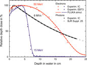
FIGURE 1. PDD profile in water for 15 MeV (blue) and 50 MeV (red) unflattened electron beams measured in this work using an ionisation chamber (dots) and EBT3 radiochromic film (crosses), and simulations using FLUKA (solid curves), in addition to PDD profile of a 6 MV, 10 cm × 10 cm photon field, measured with PTB’s clinical accelerator (black dots) and reference data set from BJR Supplement 25 [16] (triangles).
Beams of electrons with energies exceeding the clinical energy range overcome the depth limitation. Electrons with 100–250 MeV are known as very high energy electrons (VHEEs) [17, 18]. They have sharp penumbra and are insensitive to tissue inhomogeneity. In contrast to photon or proton beams, they enable better dose conformity for some tumors located in close proximity to tissue with varying densities, which also spares surrounding normal tissue [18–20]. The dosimetric benefits of VHEEs over photons have been investigated by Bazalova-Carter et al. [18] using a treatment planning system, where they compared VHEE treatment with clinical 6 and 15 MV state-of-the-art volumetric modulated arc therapy (VMAT) [21] photon plans. They reported that 100 MeV electron beams resulted in significant sparing of organs at risk (OAR), compared with conventional photon RT.
The majority of current radiotherapy treatments are administered using photon radiation produced by clinical linear accelerators. 6 MV photons, the most commonly used, deposit their maximum dose typically over a depth of 1–2 cm followed by an exponential decrease (see Figure 1 black dots), resulting in lower relative dose deposition in the depth of a deep-seated tumor (10–15 cm). However, the application of VMAT, where the radiation dose is delivered continuously as the gantry of the treatment machine rotates around the patient, enables dose to be concentrated also in a deep-seated tumor while minimizing it in the surrounding normal tissue and OAR.
The FLASH effect has been also observed with photon radiation (from a synchrotron light source) [10], but currently there is no method for generating ultra-high dose rate photon beams by means of a linear accelerator for FLASH RT of deep-seated tumors. However, 50 MeV electrons, as used in our study, can reach deep-seated tumors situated at depths of 10–15 cm (red curve in Figure 1). In contrast to photons, they can be generated with ultra-high dose rates by linear accelerators. This can enable FLASH RT also for deep-seated tumors.
Laser-driven accelerators are a promising solution for future RT machines as they are capable of producing electron bunches with energies from clinical to VHEE range suitable for depositing dose at ultra-high rates [22–25]. Research is underway to develop laser-driven accelerators for RT applications at facilities such as the Scottish Center for the Application of Plasma-based Accelerators (SCAPA), located at the University of Strathclyde in the United Kingdom. A vertical beam line utilising sub-picosecond electron bunches from a laser-driven accelerator with energies up to 150 MeV at the SCAPA facility is dedicated to in vitro and in vivo VHEE studies [26].
Accurate and reliable dosimeters are required to translate VHEE RT into the clinical stage, and also for application of sub-picosecond electron bunches from laser-driven accelerators used in pulsed radiolysis, laboratory astrophysics and warm dense matter studies. Ionisation chambers (ICs), are common detectors used in reference dosimetry for conventional external beam radiation therapy. However, they suffer from significant ion recombination effects when exposed to VHEE beams which deposit the dose at ultra-high rates and/or ultra-high dose per pulse (DPP) [27, 28]. Currently there are no dosimetry protocols available, either for FLASH RT or VHEE, nor recommendations for reliable dosimeters and validated methods for these novel modalities. At present no primary standard exists that can be used as a reference for determining the deviations of dosimeters under such conditions.
The work presented here aims to study the energy dependence of two passive, dose-rate independent detectors, EBT3 radiochromic film [29] and alanine [30], for application in electron fields of up to 50 MeV. The response of the dosimeters is compared with absolute dose measurements performed using an ionisation chamber. The DPP is reduced to a level where the ion recombination effect of the ionisation chamber type used is sufficiently small and models for quantifying the ion recombination correction are available. For this purpose, the distance to the source was increased while reducing the charge per beam pulse. An investigation of the deviations due to the ion recombination effects at ultra-high DPP as present in FLASH RT [31] and VHEE accelerators [27] is not the focus of this work.
Materials and Methods
Accelerator
The experiments have been carried out at the Metrological Electron Accelerator Facility (MELAF) [32] at the German national metrology institute Physikalisch-Technische Bundesanstalt (PTB). The facility provides a research linear accelerator (commissioned in 2012) for investigating dosimetry for radiotherapy at ultra-high pulse dose rates (the FLASH RT regime), and over a large energy range of 0.5–50 MeV. This is considerably larger than for conventional medical accelerators, which typically operate between 4 and 22 MeV. Furthermore, in contrast to commercial medical accelerators, all electron beam parameters of the PTB research accelerator are adjustable and can be measured with a high degree of accuracy. Therefore, it is possible to study radiation effects as a function of their fundamental physical quantities such as energy and fluence.
The research accelerator delivers pulsed electron beams with a fixed macropulse duration of about 2.5 μs and a 3 GHz micropulse fine structure. The term beam pulse here in the following refers to a macropulse. The accelerator provides controllable mean dose rates via variable pulse charge (about 1–150 nC per beam pulse) and adjustable pulse repetition frequency (1–100 Hz). All measurements presented here are conducted at a repetition frequency of 5 Hz. An Integrating Current Transformer (ICT), provided by Bergoz Instrumentation (in-flange version, windings ratio 50:1), is included in the beamline to non-destructively measure the charge of each electron pulse with a precision of ±0.03 nC [33]. The minimum charge per pulse used in this work is 2 nC and at least 100 pulses are measured to determine the charge with a precision better than 0.15%.
The kinetic energy of the electrons can be varied continuously, in contrast to medical accelerators where only a few fixed beam energies can be selected. The nominal energies are varied from 15 to 50 MeV with an increment of 5 MeV. The beam energy is measured with a magnetic spectrometer shortly before the dosimeters are irradiated. An example of an energy measurement is shown in Figure 2. The beams are quasi mono-energetic with full-width at half-maximum (FWHM) energy spread of less than 0.2 MeV. The measured actual energies are 15.8, 19.7, 25.6, 31.1, 36.0, 41.3, 46.1, and 49.0 MeV.
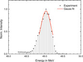
FIGURE 2. Example of an energy measurement using the magnetic spectrometer. A Gauss function is fitted to the upper part to half maximum to determine the peak position and width.
The transverse beam profile and divergence are measured using three 2d wire scanners placed at different positions along the beam line. All beams have Gaussian transverse cross-sections with a FWHM of about 3 mm and divergence of less than 0.1°. Figure 3 shows a typical measured beam profile.
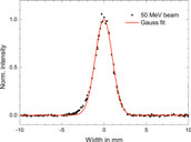
FIGURE 3. Vertical beam profile obtained for 50 MeV nominal energy with a wire scanner.
At the end of the beam line the electrons pass through a 0.1 mm thick Cu vacuum window which scatters the beam. The diameter of this window was much larger (>3 cm) than the beam width, thus all electrons detected by the ICT contributed to the radiation field. This results in an unflattened electron radiation field with a Gaussian shape. The beam width increases with decreasing energy and increasing distance from the exit window. Figure 4 shows the 2-dimensional lateral relative dose distribution of a 40 MeV electron field recorded with an IC matrix (PTW OCTAVIUS Detector 1500) positioned 1 m after the exit window in air. A 1-dimensional cross section through the central beam axis has Gaussian shape (R2 > 0.9995).
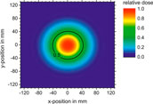
FIGURE 4. 2-dimensional dose distribution of 40 MeV electron beam in air captured with an ionisation chamber matrix (PTW OCTAVIUS 1500) 1 m from the exit window.
Setup
A 30 × 30 × 30 cm3 water phantom with 2 cm thick poly-methyl methacrylate (PMMA) walls is placed with its 0.3 cm thick PMMA entrance window in a distance of 200 cm from the beam exit window along the central beam axis. The beam FWHM at the entrance window of the phantom is greater than 8 cm for all beam energies. Custom-made PMMA holders are used to position the EBT3 films, the alanine pellets and the IC inside the water phantom. A 3-dimensional precision motorized positioning system allows i) to place the dosimeters at a certain depth along the central beam axis, ii) to perform controlled longitudinal movement of the IC along the central beam axis for depth dose measurements, and iii) to perform controlled lateral movements to determine the cross-sectional dose distribution of the radiation field. Figure 5 shows a photograph of the water phantom with the positioning systems in front of the beam line.
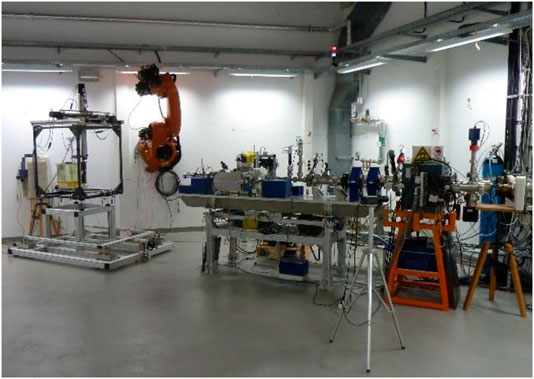
FIGURE 5. Photograph of the setup. Water phantom inside the frame of the 3D positioning system in front of the accelerator beam line.
The dosimeters are irradiated successively at the same position to ensure they receive equal dose and are irradiated with identical dose gradient within the radiation field. The beam pulse charge measured by the ICT is used as reference for successive irradiation of the different dosimeters, because the charge is proportional to the dose. Two ICs (Wellhöfer IC10) are mounted in the water phantom at the depth of the respective dosimeter under investigation, about 10 cm left and right from the central beam axis. They are used as radiation monitors to verify the ICT signal. The ratio of the signals from both radiation monitor ICs is used to verify that the maximum of the radiation field does not change its position over time. Figure 6 shows the typical response of one of the radiation monitor chambers in the water phantom as function of the signal from the ICT beam current monitor during an irradiation. The typical pulse-to-pulse charge fluctuations (<3%) are proportional to the dose response from the radiation monitor.
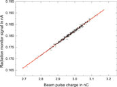
FIGURE 6. Typical response of the radiation monitor chamber in the water phantom as function of the beam pulse charge measured with the ICT.
Dosimeters
Ionisation chamber
A parallel-plate Advanced Markus IC (PTW 34045, s/n:1279) is used to determine the absorbed dose to water Dw. The signal from the IC is read out using an analogue electrometer (Keithley 616) in current mode. The reading, M, of the analogue electrometer is recorded using a 16-bit analogue-to-digital-converter and analysed using custom software. A calibrated current source (Keithley 6430) is used to calibrate the electrometer with its own read-out system. The Advanced Markus chamber is calibrated using PTB’s Co-60 reference field in terms of absorbed dose to water, which is traceable to the PTB’s primary standard water calorimeter [34].
For absolute dose measurements the signal of the Advanced Markus chamber is converted to absorbed dose to water, Dw, following the German protocol DIN 6800-2 recommendations [35] for dosimetry in conventional radiotherapy:
where N′Co60,Dw is the calibration factor of the chamber with respect to Co-60 radiation, M is the reading of the dosimeter corrected for the reading without irradiation M0, kE is the quality correction factor accounting for the difference in detector’s response between Co-60 radiation and high-energy electron radiation, and kS is the correction factor for ion recombination. The factors kP and kT,p take into account the effects of polarity and the ambient conditions, respectively. The reference conditions, procedures and the approximation formulas in the DIN 6800-2 [35] are consistent with those in IAEA’s Code of Practice (CoP) TRS398 [36, 37].
The radiation quality correction factor kE in Eq. 1 is the product of a chamber design dependent constant
where the half-value depth, i.e., the depth at which the absorbed dose is dropped to 50% of its maximum value, R50, of the energy dependent depth dose distribution is given in cm. Equation 2 is valid only for the measurements at the reference depth, zref, which is determined by:
where R50 and zref are expressed in cm. R50 must be determined experimentally for each energy from the half-value depth of the ionisation current depth curve R50,Ion, i.e., the half-value depth of the chamber signal as a function of the depth in water, by
The ion recombination correction factor,
The high DPP range (20–120 mGy/pulse) delivered by linear accelerators in IORT is comparable to the DPP range used in this work. Extensive studies have been carried out on ion recombination effects of ICs for high DPP beams [39–42]. A method of determining kS for high DPP ranges without using a dose reference has been introduced by Laitano et al. [39]. This approach takes into account free electrons produced in the chamber, which are collected by the anode without being attached to oxygen molecules, described by three different models proposed by Boag et al. [43]. This approach has been applied by Pimpinella et al. [42] with the assumption that the third Boag’s model provides the best description. The approach of Laitano et al. [39] with the third Boag’s model is used in this work as second method for ks determination. The free-electron fraction p is calculated according to Laitano et al. [39] for the Advanced Markus chamber to yield p = 0.6855. Then numerical calculations using formula A.3 in the appendix of Ref. 39 are carried out.
The polarity effect of the Advanced Markus chamber has been investigated for clinical electron beams by Pearce et al. [44] who observed a large polarity correction effect for lower energy clinical beams (≈4 MeV). However, with increase in energy the correction due to polarity diminished, which for 9 MeV is 0.48%. In this work kp = 1 is assumed and an uncertainty of 0.5% is assigned. The correction factor kT,P has been calculated from pressure and temperature measured during IC exposures and found to be between −0.3 and +0.6 %.
To determine the dose at a depth other than zref an additional correction factor kNR, E must be included in Eq. 2. The PDD in Figure 1 results from the signal of the Advance Markus chamber after the conversion to a dose by taking into account kNR, E according to DIN 6800-2 [35].
Alanine
The alanine pellets are produced with diameter of 5 and 3 mm height. The pellets are arranged in stacks of 8 pellets to form a cylinder. The alanine stacks are positioned within a PMMA tube at zref with the longer dimension perpendicular to the beam central axis. Their response is temperature dependent (0.18%/°C) [45]. To account for this dependence, and to ensure that the pellets are at thermal equilibrium with their environment, the temperature of the water is recorded, and irradiation not commenced until the pellets have been immersed for about 10 min. At each energy an alanine stack is irradiated with a nominal dose of 15 Gy while the charge of the electron beam pulses was simultaneously measured. Uncertainties of 0.4–0.6% (k = 1) are reached at Co-60 radiation for irradiations in the range of 5–25 Gy [46]. For the conversion of the alanine’s response to electron radiation an additional radiation quality correction factor kEala has to be applied. This factor is known with an uncertainty of 1 % for electron energies up to 22 MeV [47]. A detailed description of PTB’s alanine dosimetry system and readout of the irradiated pellets can be found elsewhere [46–49].
GafChromic™ EBT3 films
GafChromic™ EBT3 films (www.gafchromic.com) from lot #06141702 (chemical composition provided in Supplementary Table S1) are used to measure the dose absorbed to water. The films are placed at zref and exposed to 6 dose levels between 5 and 20 Gy for all electron energies, while keeping all other beam settings fixed. The doses are delivered by varying the number of beam pulses in the range of 140–1600. The pulse charge is recorded with the ICT.
Stacks of equispaced films in a dedicated holder, as shown in Figure 7, are used to measure PDD profiles for all energies. All films in the stack together are 0.28 cm thick. The water equivalent thickness of the whole stack is about 0.3 cm. The measured PDD profiles are compared with those obtained with the IC and Monte Carlo (MC) simulations.
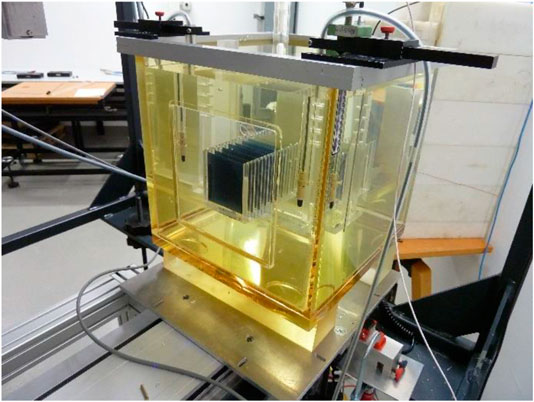
FIGURE 7. Stack of equispaced EBT3 films in a dedicated holder after exposure to electron beam.
All films are scanned one week after irradiation to avoid differences in film self-development after exposure [50]. A multichannel flatbed EPSON Expression 10000XL Pro scanner is used to record the digital image of each film. All films are scanned in the same orientation to avoid variations in optical properties due to scanning orientation [51]. Images are measured in transmission using the RGB-positive mode at a depth of 16 bits per color channel with a spatial resolution of 127 dpi, which corresponds to a pixel size of 0.2 mm × 0.2 mm. Images are saved in TIFF format and analysed using a python script, following the protocol described by Devic et al. [50]. A single unexposed piece of film, which is kept together with the exposed films, is used as a control. A Wiener filter is applied to the irradiated and control film images.
A region of interest (ROI) of 25 × 25 pixels (5 × 5 mm2) is selected from the central area of the film, which is comparable with the cross-section of the sensitive volume of the Advanced Markus chamber (5 mm in diameter). The average pixel value (PV) within the ROI is used to calculate the net optical density (netOD), which is the change in optical density before and after irradiation, given by netOD = log10(PVbefore/PVafter). Absolute response is determined using the green color channel, which is preferable for doses up to 40 Gy [52, 53].
Calibration of the EBT3 film has been performed at NPL with 12 MeV electron beams and a dose rate of 600 cGy/min using a clinical linear accelerator (Elekta Synergy). To avoid variations due to different lot numbers, film from the same batch is used for both the measurements at PTB and calibration at NPL. The irradiation is performed in a 30 × 30 × 30 cm3 solid-water phantom at 5 different dose levels between 1 and 20 Gy under reference conditions (source-to-surface distance of 100 cm and 20 × 20 cm2 field size) at zref = 2.8 cm. The dose delivered to each film have been established based on the output measurements at reference conditions using a Roos IC (PTW 34001), which has been traceably calibrated in terms of Dw to NPL’s primary standard graphite calorimeter [54]. The dose is determined from the netOD values and the dose-response calibration curve is fitted using the following analytical function:
where a, b and n are fit parameters.
Monte Carlo Simulation
Simulations have been carried out using the FLUKA MC code (FLUKA2011 Version 2x.7) [55, 56] with 107 particles and 10 cycles. The physics settings are described in the FLUKA manual under the physics package PRECISIOn. The photonuclear reactions are activated by the card PHOTONUC. The threshold for transport and production of δ-particles and photons (ECUT, PCUT) is set to 10 keV.
In the model, a monoenergetic parallel beam with a Gaussian cross-section (3 mm FWHM) is scattered by the 0.1 mm thick Cu foil of the vacuum exit window at the end of the beam line. The incident electron beam parameters are measured (see section Accelerator). The electrons propagate in air from the source (exit window) to the phantom.
The dose distribution in water is simulated by a 30 × 30 × 30 cm3 water cube defined with a FLUKA USRBIN mesh that has a resolution of 0.065 cm. The on-axis dose is calculated within a 0.5 × 0.5 × 30 cm3 rectangular volume around the central beam axis.
Results and Discussion
EBT3 Film Calibration
The red crosses in Figure 8 shows the reference dose applied to the EBT3 films at NPL as a function of the resulting netOD value obtained from the respective film. The data points are fitted to the analytical function given in Eq. 6 (red curve).
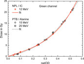
FIGURE 8. Reference dose applied to the EBT3 films at NPL plotted against the resulting netOD values from the green channel (red crosses). Also shown are the doses applied to the EBT3 films at PTB, measured with alanine, at 15 and 20 MeV, respectively (open circles and squares, respectively). The solid and dashed lines represent fits using Eq. 6.
The radiation quality correction factor kEala to correct alanine’s response for electron radiation is known up to 22 MeV [47]. The alanine dose measurements for 15 and 20 MeV can therefore be traced to the PTB’s primary standard. They can, in turn, be used to calibrate EBT3 film irradiated under the same conditions. For comparison, the doses determined using alanine for 15 and 20 MeV are plotted as function of the corresponding netOD values in Figure 8 as open circles and squares, respectively. The resulting dose-response calibration curve from a fit to Eq. 6 is also shown. It is similar to the NPL’s calibration curve. In the studied dose range of 5–20 Gy the resulting dose difference between NPL and PTB calibration can vary from −1% up to 4%. The dose values determined with EBT3 in this work are based on the NPL calibration function.
Ion Recombination Correction for the Advanced Markus Ionisation Chamber
The mean dose rates used in this investigation vary between 3 and 12 Gy/min, which is within the range of conventional radiotherapy. However, the DPP, ranging from 10 mGy to 40 mGy per pulse, is significantly higher than for a medical accelerator (0.1–3 mGy per pulse) and comparable with that used in IORT, where non-negligible ion recombination effects have been reported [39, 40, 42, 57, 58]. Two approaches for evaluation of a kS factors i) the Jaffé plots and ii) the method described by Laitano et al. [39] (described in section Ionisation Chamber) were applied and compared against each other.
Figure 9 shows Jaffé plots for the lower and upper edge of the studied DPP range. The y-intercept (1/ks) of the linear fits is 0.98 and 0.94, respectively, yielding kS of 1.02 and 1.06. These ion recombination correction factors are significantly higher than in conventional RT (typically <1.01).
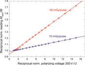
FIGURE 9. Jaffé plots: reciprocal readings 1/M of the Advance Markus chamber as function of the reciprocal chamber voltages 1/U, normalized to the reading at 300 V for 10 mGy/pulse (blue circles) and 40 mGy/pulse (red circles), respectively. Solid lines represent linear fits to the data points.
The open circles in Figure 10 represents kS factors determined using the Jaffé plots approach. The dashed red line represents the ks function given by Bruggmoser et al. [38]
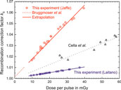
FIGURE 10. kS factor as a function of dose per pulse determined for the Advanced Markus chamber at 300 V operating voltage using Jaffé plots (open circles) and approach from Laitano et al. [39] (open squares). For comparison, the kS function from Bruggmoser et al. [38], recommend in the DIN 6800-2 protocol, is shown in the range where determined experimentally (dashed red line) and extrapolated to the high DPP range used in the current experiment (solid red line). Also shown are the results from an experimental determination by Cella et al. [40] using a Fricke dosimeter as reference. Lines: linear fits.
For comparison, the results from an experimental determination of ks from Cella et al. [40] are also shown in Figure 10. These were determined by comparing the dose determined with an Advanced Markus chamber without taking into account any recombination effects against a reference dose determined with Fricke dosimeters, i.e., no theoretical assumptions were needed. In the relevant DDP range these values are about 0.3–1.5% larger than the results from this work using Laitano’s approach.
Comparison of Different Methods for Relative Dose Measurements
Figure 1 shows relative depth dose curves measured with the IC and EBT3 films for 15 and 50 MeV electron beams produced by the PTB research accelerator using the experimental setup described in Setup. The measurements have been compared with Monte Carlo calculations carried out using FLUKA, which incorporates an accurate physics model of electron interactions with matter within the investigated energy range. The ion chamber measurements for the 50 MeV beam are in excellent agreement with the MC simulations. However, some discrepancy exists between measured and calculated data for the 15 MeV beam at 1–3 cm. The PDD measured at discrete positions with EBT3 films is significantly more scattered compared to the IC measurement due to substantial uncertainties associated with this detector, which can easily reach 5% [52]. They vary between +3 and −9% with respect to the PDD measured with the IC.
The radiation field at the depth of the detectors is not homogenous, in particular at higher energies. Therefore, the relative dose distributions in lateral directions are recorded for each energy at two different depths to determine the exact position of the beam central axis at dose maximum. Figure 11 shows lateral dose distributions for the two extremes of the electron energy range used in this study and thus the narrowest and broadest radiation field used at PTB.
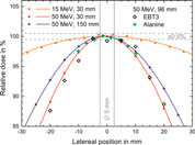
FIGURE 11. The lateral dose profiles for 15 and 50 MeV at 30 mm depth in water as well as for 50 MeV at 150 mm depth measured with the ionisation chamber (solid symbols). Also shown are the results of EBT3 films in 5 mm steps (open diamonds), and the stack of 8 alanine pellets (green crosses) for 50 MeV at 96 mm depth. Solid lines represent Gaussian fits to the data points. The vertical bar indicates the position and size of the sensitive volume of the Advanced Markus chamber (5 mm).
The variations in dose within the sensitive volume of the Advanced Markus Chamber (±2.5 mm from the beam axis, marked in Figure 11) is less than 0.5%, even for the narrowest radiation field (50 MeV). This indicates that on the beam axis the deviation due to non-uniform radiation fields is negligible. The data points from the stack of 8 alanine pellets (green crosses) are consistent with the IC results. The data points from the radiochromic film (open diamonds) scatters more than IC and alanine data but represent well the lateral profile.
Figure 12 shows R50 measured as function of electron energy. The relative depth dose profiles have been measured and calculated for all beam energies. The agreement between the FLUKA simulations and IC measurements, shown in Figures 1 and 12, indicate that the dosimetry procedures recommended by DIN6800-2 for homogeneous fields are also applicable to unflattened radiation fields, as investigated in this work.
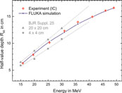
FIGURE 12. R50 plotted as function of the energy, measured with the IC (red crosses) and calculated using FLUKA (blue dots) for the inhomogeneous field. The reference data from BJR Supplement 25 [16] for homogeneous radiation fields with 20 × 20 cm2 (triangles) and 4 × 4 cm2 (squares) field sizes are included for comparison. Dashed lines represent linear extrapolations to higher energies.
R50 depends on the energy and the field size. For comparison, the R50 values established in this study are plotted in Figure 12 together with the R50 values determined for 20 × 20 cm2 and 4 × 4 cm2 fields. The R50 of the used unflattened Gaussian shaped field is in between the R50 values of the small and the large flat fields. With increasing energy, the width of the radiation field becomes smaller and thus R50 tends to the extrapolated line for the smaller field.
Comparison of Different Methods for Absolute Dose Measurements
None of the three dose measurement methods can serve as a reference because one cannot rule out effects due to non-standard radiation fields. Therefore, the three dosimetry methods can only be compared against each other. Figure 13 shows the dose at zref per unit charge measured by the ICT, for the three different dosimeters as a function of electron beam energy. The dose rises with increase in energy. The slope increases because the width of the radiation field decreases with increasing energy and thus a larger fraction of the beam electrons deposits energy close to the central beam axis. A least square fit of a 2nd order polynomial function is fitted to all data points of the three dosimeters to evaluate deviations of each point from the common trend. Figure 14 shows the percentage deviation (for the three types of detectors) from the fit function.
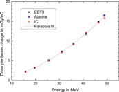
FIGURE 13. Dose per unit charge measured with EBT3 film (crosses), alanine (squares), and ionisation chamber (circles) at the reference depth. Dashed curve represents 2nd order polynomial fit to all data points.
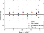
FIGURE 14. Deviation of the dose response for EBT3 films (green channel), alanine and IC, from the fit curve shown in Figure 13.
The response of EBT3 films has been averaged over 6 measurements (gray dots) carried out for doses in the range 5–20 Gy. The data points for single films are scattered within several percent (max. 9%) around the common mean value for all dosimeters (Zero line in Figure 14). The deviation (σ = 3.7%) is not correlated with the delivered dose or beam energy. The mean values of the 6 measurements (crosses) agree with the mean of the alanine and IC results to within 3%. No energy dependence is observed within the uncertainty.
The dose at the central beam axis from the dose measurements with the stack of 8 alanine pellets is obtained as the maximum of a Gaussian fit to the 8 doses captured along the lateral beam profile (see green crosses in Figure 11). The blue squares in Figure 14 represent the percentage deviation of the alanine dosimeter measurements from the common trend. The relative uncertainty was estimated to 1.1% (k = 1). The main contribution is the uncertainty in the radiation quality correction factor kEala (1%) [47]. No beam quality dependence is observed within investigated energy range. This indicates that the assumption that kEala is constant, as it is at lower energies [47], is adequate. A systematic shift of 1.9% on average can be observed, with respect to the results from the IC evaluated using ks from Laitano’s approach (open circles in Figure 14). This may indicate that this ks is too small. If the fit function to the results of Cella et al. [40] (dotted line in Figure 10) is used, then the mean deviation is about 0.9%. The relative uncertainty of the IC measurements is estimated to be 1.5%. Therefore, the average shift is within the uncertainties. However, the variation in the difference between IC and alanine results (0.4% at 40 MeV, 3.8% at 50 MeV) cannot explained by the considered uncertainty contributions: the uncertainty of alanine without the contribution of the constant kEala is only 0.4% and the approximations that introduce an uncertainty when converting the IC signal into a dose are smooth functions of energy. Approaches taking into account the free electrons at determination of ks are associated with large uncertainty [39] but IC measurements with different DPP are consistent with each other (multiple data points for IC at each energy in Figure 14). Due to the relatively large scattering of the difference between alanine and IC measurement it is not possible to make a conclusion about whether Laitano’s approach is correct. Further investigations with lower measurement uncertainty are planned to reveal the cause of the systematic difference between IC and alanine dose determination and its variation.
Neither the DIN 6800-2 [35] nor the TRS398 [36] protocol provide recommendations for high DPP beams, or mention limits due to effects of the free electron fraction in determining ks. Petersson et al. [31] reported up to 75% ion collection losses due to recombination effects for ultra-high DPP beams in FLASH RT (hundreds of mGy/pulse to few Gy/pulse). The data presented in the published literature [39, 42, 57, 58] and in this work indicates that there is a strong need to develop a clear dosimetry guidance to support accurate dosimetry of high and ultra-high DPP beams.
Conclusion
Three different dosimetry methods, including EBT3 radiochromic film, ionisation chamber, and alanine, have been investigated for electron beams with energies exceeding the clinical range up to 50 MeV in support of future studies of VHEE radiotherapy, and FLASH radiotherapy with VHEE beams.
All three methods provide similar results for relative dosimetry (depth dose curve, lateral dose profile). However, results from the EBT3 film has a variance of several percent, when compared with IC and alanine measurements. The half-value depth of measured percentage depth dose profiles of the unflattened radiation fields agrees well with MC simulations. This indicates that the dosimetry procedures for homogeneous fields are also applicable to unflattened radiation fields.
The ion recombination correction factor for the Advanced Markus IC is determined with an approach which considers free electrons. Comparing this approach with the results from Jaffé plots it is found that the latter yields 1.5–5% higher values for the high dose-per-pulse range.
The absolute dose measurements of the three methods have been compared against each other. For all beam energies single EBT3 film measurements show relatively high percentage deviations (up to 9%) over the dose range independent of the delivered dose. However, the mean values of 6 measurements agree well with the mean of the dose values from IC and alanine (mean deviation 1.2%, maximum deviation 3%). No energy dependence is observed within the uncertainty in the investigated energy range up to 50 MeV.
Data Availability Statement
All datasets presented in this study are included in the article/Supplementary Material. Data associated with research published in this paper is available at https://doi.org/10.15129/ef9926f7-6177-4650-9768-91ac42fdf0ee.
Author Contributions
KK, ASc, EB, MM, and TH performed the measurements at PTB. ASc evaluated the IC measurements. RK calculated the correction for ion recombination. TH prepared and evaluated the alanine samples. KK read doses from the radiochromic films. The calibration of films with clinical linear accelerator at NPL was carried out by KK and ASu. KK and EB carried out the FLUKA simulations and analysis. DJ conceived the project and provided overall leadership. R-PK oversaw the research at PTB. All authors contributed to the analysis and interpretation of the results in addition to writing the manuscript.
Funding
This project has received funding from the EMPIR program co-financed by the Participating States, from the European Union’s Horizon 2020 research and innovation program. This work was funded by EPSRC (grant no. EP/J018171/1, EP/J500094/1 and EP/N028694/1) and the EC’s LASERLAB-EUROPE (grant nos. 654148 and 871124).
Conflict of Interest
RK is employed by Physikalisch-Technische Werkstätten (PTW)
The remaining authors declare that the research was conducted in the absence of any commercial or financial relationships that could be construed as a potential conflict of interest.
Acknowledgments
We would like to thank to Christoph Makowski for the maintenance and operation of the electron accelerator.
Supplementary Material
The Supplementary Material for this article can be found online at: https://www.frontiersin.org/articles/10.3389/fphy.2020.568302/full#supplementary-material
References
1. Rosenblatt E, Zubizarreta E. Radiotherapy in cancer care: facing the global challenge. Vienna: International Atomic Energy Agency (2017). https://www-pub.iaea.org/MTCD/Publications/PDF/P1638_web.pdf.
2. Delaney G, Jacob S, Featherstone C, Barton M. The role of radiotherapy in cancer treatment. Cancer. (2005). 104:1129–37. doi:10.1002/cncr.21324
3. Slotman BJ, Leer JWH. Infrastructure of radiotherapy in The Netherlands: evaluation of prognoses and introduction of a new model for determining the needs. Radiother Oncol. (2003). 66:345–9. doi:10.1016/s0167-8140(03)00025-2
4. Favaudon V, Caplier L, Monceau V, Pouzoulet F, Sayarath M, Fouillade C, et al. . Ultrahigh dose-rate flash irradiation increases the differential response between normal and tumor tissue in mice. Sci Transl Med. (2014). 6:245–93. doi:10.1126/scitranslmed.3008973
5. Durante M, Bräuer-Krisch E, Hill M. Faster and safer? FLASH ultra-high dose rate in radiotherapy. Br J Radiol. (2018). 91:20170628. doi:10.1259/bjr.20170628
6. Vozenin M.-C, Hendry JH, Limoli CL. Biological benefits of ultra-high dose rate FLASH radiotherapy: sleeping beauty awoken. Clin Oncol. (2019). 31:407–15. doi:10.1016/j.clon.2019.04.001
7. Bourhis J, Sozzi WJ, Jorge PG, Gaide O, Bailat C, Duclos F, et al. . Treatment of a first patient with flash-radiotherapy. Radiother Oncol. (2019). 139:18–22. doi:10.1016/j.radonc.2019.06.019
8. Bourhis J, Montay-Gruel P, Gonçalves Jorge P, Bailat C, Petit B, Ollivier J, et al. . Clinical translation of FLASH radiotherapy: why and how? Radiother Oncol. (2019). 139:11–7. doi:10.1016/j.radonc.2019.04.008
9. Montay-Gruel P, Petersson K, Jaccard M, Boivin G, Germond J.-F, Petit B, et al. . Irradiation in a flash: unique sparing of memory in mice after whole brain irradiation with dose rates above 100 Gy/s, Radiother Oncol. (2017). 124:365–9. doi:10.1016/j.radonc.2017.05.003
10. Montay-Gruel P, Bouchet A, Jaccard M, Patin D, Serduc R, Aim W, et al. . X-rays can trigger the FLASH effect: ultra-high dose-rate synchrotron light source prevents normal brain injury after whole brain irradiation in mice. Radiother Oncol. (2018). 129:582–8. doi:10.1016/j.radonc.2018.08.016
11. Vozenin M.-C, De Fornel P, Petersson K, Favaudon V, Jaccard M, Germond J.-F, et al. . The advantage of flash radiotherapy confirmed in mini-pig and cat-cancer patients. Clin Cancer Res. (2019). 25:35. doi:10.1158/1078-0432.ccr-17-3375
12. Jaccard M, Durán MT, Petersson K, Germond J.-F, Liger P, Vozenin M.-C, et al. . High dose-per-pulse electron beam dosimetry: commissioning of the oriatron ert6 prototype linear accelerator for preclinical use. Med Phys. (2018). 45:863–74. doi:10.1002/mp.12713
13. Favaudon V, Lentz J.-M, Heinrich S, Patriarca A, de Marzi L, Fouillade C, et al. . Time-resolved dosimetry of pulsed electron beams in very high dose-rate, FLASH irradiation for radiotherapy preclinical studies. Nucl Instrum Methods Phys Res Sect A Accel Spectrom Detect Assoc Equip. (2019). 944:162537. doi:10.1016/j.nima.2019.162537
14. Schüler E, Stefania T, Gregory K, Frederick L, Marjan R, Manuel V, et al. . Experimental platform for ultra-high dose rate FLASH irradiation of small animals using a clinical linear accelerator. Int J Radiat Oncol Biol Phys. (2017). 97:195–203. doi:10.1016/j.ijrobp.2016.09.018
15. Lempart M, Blad B, Adrian G, Bäck S, Knöös T, Ceberg C, et al. . Modifying a clinical linear accelerator for delivery of ultra-high dose rate irradiation. Radiother Oncol. (2019). 139:40–5. doi:10.1016/j.radonc.2019.01.031
16.The British Journal of Radiology Supplement 25. Central axis depth dose data for use in radiotherapy. London, UK: British Institute of Radiology (1996). ISBN 0905749383.
17. DesRosiers C, Moskvin V, Bielajew AF, Papiez L. 150–250 MeV electron beams in radiation therapy. Phys Med Biol. (2000). 45:1781–805. doi:10.1088/0031-9155/45/7/306
18. Bazalova-Carter M, Qu B, Palma B, Hårdemark B, Hynning E, Jensen C, et al. . Treatment planning for radiotherapy with very high-energy electron beams and comparison of VHEE and VMAT plans. Med Phys. (2015). 42:2615–25, doi:10.1118/1.4918923
19. Palma B, Bazalova-Carter M, Hårdemark B, Hynning E, Qu B, Loo BW, et al. . Assessment of the quality of very high-energy electron radiotherapy planning. Radiother Oncol. (2016). 119:154. doi:10.1016/j.radonc.2016.01.017
20. Schüler B, Eriksson K, Hynning E, Hancock SL, Hiniker SM, Bazalova-Carter M, et al. . Very high-energy electron (VHEE) beams in radiation therapy; treatment plan comparison between VHEE, VMAT, and PPBS. Med Phys. (2017). 44:2544–55. doi:10.1002/mp.12233
21. Teoh M, Clark CH, Wood K, Whitaker S, Nisbet A. Volumetric modulated arc therapy: a review of current literature and clinical use in practice. Brit J Radiol. (2011). 84:967–996. doi:10.1002/mp.12233
22. Giulietti A. Laser-driven particle acceleration towards radiobiology and medicine, biological and medical physics, biomedical engineering. Berlin: Springer (2016).
23. Mangles SPD, Murphy CD, Najmudin Z, Thomas AGR, Collier JL, Dangor AE, et al. . Monoenergetic beams of relativistic electrons from intense laser-plasma interactions. Nature. (2004). 431:535–8. doi:10.1038/nature02939
24. Kokurewicz K, Brunetti E, Welsh GH, Wiggins SM, Boyd M, Sorensen A, et al. . Focused very high-energy electron beams as a novel radiotherapy modality for producing high-dose volumetric elements. Sci Rep. (2019). 9:10837. doi:10.1038/s41598-019-46630-w
25. Malka V, Faure J, Gauduel YA. Ultra-short electron beams based spatio-temporal radiation biology and radiotherapy. Mutat Res Rev Mutat Res. (2010). 704:142–51. doi:10.1016/j.mrrev.2010.01.006
26. Wiggins SM, Marie B, Enrico B, Nick MHB, James SF, Ross JG, et al. Application programmes at the Scottish Centre for the application of plasma-based accelerators (SCAPA). Proc SPIE. (2019). 11036:110360T. doi:10.1117/12.2520717
27. McManus M, Romano F, Lee ND, Farabolini W, Gilardi A, Royle G, et al. The challenge of ionisation chamber dosimetry in ultra-short pulsed high dose-rate Very High Energy Electron beams. Sci Rep. (2020). 10:9089. doi:10.1038/s41598-020-65819-y
28. Subiel A, Moskvin V, Welsh GH, Cipiccia S, Reboredo D, DesRosiers C, et al. . Challenges of dosimetry of ultra-short pulsed very high energy electron beams. Phys Med. (2017). 42:327–31. doi:10.1016/j.ejmp.2017.04.029
29. Jaccard M, Petersson K, Buchillier T, Germond J.-F, Durán MT, Vozenin M.-C, et al. . High dose-per-pulse electron beam dosimetry: usability and dose-rate independence of EBT3 Gafchromic films. Med Phys. (2017). 44:725–35. doi:10.1002/mp.12066
30. Kudoh H, Celina M, Kaye RJ, Gillen KT, Clough RL. Response of alanine dosimeters at very high dose rate. Appl Radiat Isot. (1997). 48:497–9. doi:10.1016/s0969-8043(96)00281-3
31. Petersson K, Jaccard M, Germond J.-F, Buchillier T, Bochud F, Bourhis J, et al. . High dose-per-pulse electron beam dosimetry—a model to correct for the ion recombination in the Advanced Markus ionization chamber. Med Phys. (2017). 44:1157–67. doi:10.1002/mp.12111
32. Schüller A, Pojtinger S, Meier M, Makowski C, Kapsch R-P. The metrological electron accelerator facility (MELAF) for research in dosimetry for radiotherapy, IFMBE Proc. (2018). 68:589–93. doi:10.1007/978-981-10-9023-3_109
33. Schüller A, Illemann J, Renner F, Makowski C, Kapsch R-P. Traceable charge measurement of the pulses of a 27 MeV electron beam from a linear accelerator, J Inst Met. (2017). 12:P03003. doi:10.1088/1748-0221/12/03/p03003
34. Krauss A. The PTB water calorimeter for the absolute determination of absorbed dose to water in60Co radiation. Metrologia. (2006). 43:259–72. doi:10.1088/0026-1394/43/3/008
35.DIN 6800-2:2008-03. Procedures of dosimetry with probe type detectors for photon and electron radiation—Part 2: ionization chamber dosimetry of high energy photon and electron radiation. Berlin, Germany: Beuth Verlag
36.International Atomic Energy Agency. Absorbed dose determination in external beam radiotherapy (2001). Technical Rep. Series No. 398. Vienna: IAEA.
37. Hartmann GH. Absorbed dose determination for high energy photon and electron beams at a PRIMUS linear accelerator using the documents DIN 6800-2 and TRS-398. Z Med Phys. (2003). 13:241–50. doi:10.1078/0939-3889-00183
38. Bruggmoser G, Saum R, Schmachtenberg A, Schmid F, Schüle E. Determination of the recombination correction factorkSfor some specific plane-parallel and cylindrical ionization chambers in pulsed photon and electron beams. Phys Med Biol. (2007). 52, N35–N50. doi:10.1088/0031-9155/52/2/N01
39. Laitano RF, Guerra AS, Pimpinella M, Caporali C, Petrucci A. Charge collection efficiency in ionization chambers exposed to electron beams with high dose per pulse, Phys Med Biol. (2006). 51:6419. doi:10.1088/0031-9155/51/24/009
40. Cella L, Liuzzi R, Salvatore M. The Italian affair: the employment of parallel-plate ionization chambers for dose measurements in high dose-per-pulse IORT electron beams. Med Phys. (2010). 37:2918–24. doi:10.1118/1.3432601
41. Besheli MG, Ioannis S, Klemens Z, Budach W. Determination of the ion recombination correction factor for intraoperative electron beams. Z Med Phys. (2016). 26:35–44.
42. Pimpinella M, Andreoli S, De Angelis C, Della Monaca S, D'Arienzo M, Menegotti L. Output factor measurement in high dose-per-pulse IORT electron beams. Phys Med. (2019). 61:94–102. doi:10.1016/j.ejmp.2019.04.021
43. Boag JW, Hochhäuser E, Balk OA. The effect of free-electron collection on the recombination correction to ionization measurements of pulsed radiation. Phys Med Biol. (1996). 41:885–97. doi:10.1088/0031-9155/41/5/005
44. Pearce J, Thomas R, DuSautoy A. The characterization of the Advanced Markus ionization chamber for use in reference electron dosimetry in the UK. Phys Med Biol. (2006). 51:473–83. doi:10.1088/0031-9155/51/3/001
45. Puhl JM, Desrosiers MF. Advancements in accuracy of the alanine dosimetry system. Part 2. The influence of the irradiation temperature. Radiat Phys Chem. (2000). 57:1–9. doi:10.1016/s0969-806x(99)00339-4
46. Anton M. Uncertainties in alanine/ESR dosimetry at the physikalisch-technische Bundesanstalt. Phys Med Biol. (2006). 51:5419–40. doi:10.1088/0031-9155/51/21/003
47. Vörös S, Anton M, Boillat B. Relative response of alanine dosemeters for high-energy electrons determined using a Fricke primary standard. Phys Med Biol. (2012). 57:1413–32. doi:10.1088/0031-9155/57/5/1413
48. Anton M, Allisy-Roberts PJ, Kessler C, Burns DT. A blind test of the alanine dosimetry secondary standard of the PTB conducted by the BIPM. Metrologia. (2014). 51:06001. doi:10.1088/0026-1394/51/1a/06001
49. Anton M, Kapsch R-P, Krauss A, von Voigts-Rhetz P, Zink K, McEwen M. Difference in the relative response of the alanine dosimeter to megavoltage x-ray and electron beams. Phys Med Biol. 58:3259–3282. doi:10.1088/0031-9155/58/10/3259
50. Devic S, Tomic N, Lewis D Reference radiochromic film dosimetry: Review of technical aspects. (2016). Phys Med. 32:541–56. doi:10.1016/j.ejmp.2016.02.008
51. Poppinga D, Schoenfeld AA, Doerner KJ, Blanck O, Harder D, Poppe B. A new correction method serving to eliminate the parabola effect of flatbed scanners used in radiochromic film dosimetry. Med Phys. (2014). 41:021707. doi:10.1118/1.4861098 | .
52. Marroquin EYL, Herrera González JA, Camacho López MA, Barajas JEV, García-Garduño OA. Evaluation of the uncertainty in an EBT3 film dosimetry system utilizing net optical density. J Appl Clin Med Phys. (2014). 17(5):466. doi:10.1120/jacmp.v17i5.6262
53. Borca VC, Pasquino M, Russo G, Grosso P, Cante D, Sciacero P, et al. . Dosimetric characterization and use of GAFCHROMIC EBT3 film for IMRT dose verification. J Appl Clin Med Phys. (2013). 14:158–71. doi:10.1120/jacmp.v14i2.4111
54. McEwen MR. The calibration of therapy level electron beam ionization chambers in terms of absorbed dose to water. Phys Med Biol. (2006). 43:9. doi:10.6028/nist.sp.250-40
55. Andersen V, Ballarini F, Battistoni G, Cerutti F, Empl A, Fassó A, et al. . The application of FLUKA to dosimetry and radiation therapy. Radiat Protect Dosim. (2005). 116:113–7. doi:10.1093/rpd/nci040
56. Battistoni G, Boehlen T, Cerutti F, Chin PW, Esposito LS, Fassò A, et al. . Overview of the FLUKA code. Ann Nucl Energy. (2015). 82:10–8. doi:10.1016/j.anucene.2014.11.007
57. Di Martino F, Giannelli M, Traino AC, Lazzeri M. Ion recombination correction for very high dose-per-pulse high-energy electron beams. Med Phys. (2005). 32:2204–10. doi:10.1118/1.1940167
58. Scalchi P, Ciccotelli A, Felici G, Petrucci A, Massafra R, Piazzi V, et al. . Use of parallel-plate ionization chambers in reference dosimetry of NOVAC and LIACmobile electron linear accelerators for intraoperative radiotherapy: a multi-center survey. Med Phys. (2017). 44:321–32. doi:10.1002/mp.12020
Keywords: radiochromic films, dosimetry, very high energy electrons, very high energy electron radiotherapy, dose-rate independent detectors, alanine dosimetry, ionisation chamber, ion recombination correction
Citation: Kokurewicz K, Schüller A, Brunetti E, Subiel A, Kranzer R, Hackel T, Meier M, Kapsch R-P and Jaroszynski DA (2020) Dosimetry for New Radiation Therapy Approaches Using High Energy Electron Accelerators. Front. Phys. 8:568302. doi: 10.3389/fphy.2020.568302
Received: 31 May 2020; Accepted: 28 September 2020;
Published: 13 November 2020.
Edited by:
Yolanda Prezado, INSERM U1021 Signalisation normale et pathologique de l’embryon aux thérapies innovantes des cancers, FranceReviewed by:
Till Tobias Böhlen, Centre Hospitalier Universitaire Vaudois (CHUV), SwitzerlandFabio Di Martino, Pisana University Hospital, Italy
Copyright © 2020 Kokurewicz, Schüller, Brunetti, Subiel, Kranzer, Hackel, Meier, Kapsch and Jaroszynski. This is an open-access article distributed under the terms of the Creative Commons Attribution License (CC BY). The use, distribution or reproduction in other forums is permitted, provided the original author(s) and the copyright owner(s) are credited and that the original publication in this journal is cited, in accordance with accepted academic practice. No use, distribution or reproduction is permitted which does not comply with these terms.
*Correspondence: Enrico Brunetti, ZW5yaWNvLmJydW5ldHRpQHN0cmF0aC5hYy51aw== Dino A. Jaroszynski, ZC5hLmphcm9zenluc2tpQHN0cmF0aC5hYy51aw==