 Chen Xu
 Umair Ali Khan
 Salman Ghafoor
 Jawad Mirza
 Abdulah Jeza Aljohani
 Imran Aziz
- 1GUILIN University of Electronic Technology, Guilin, China
- 2School of Electrical Engineering and Computer Science (SEECS), National University of Sciences and Technology, Islamabad, Pakistan
- 3SEECS Photonics Research Group, Islamabad, Pakistan
- 4Department of Electrical and Computer Engineering, King Abdulaziz University, Jeddah, Saudi Arabia
- 5Department of Physics and Astronomy, Uppsala University, Uppsala, Sweden
Optical wireless communication (OWC) offers significant advantages over traditional radio frequency systems due to its high bandwidth, ease of deployment, license-free operation, immunity to electromagnetic interference, and inherent security benefits. This research presents a novel all-optical technique for transmitting multiple data channels over an optical link, employing Differential Phase-Shift Keying (DPSK) and Pulse Position Modulation (PPM) schemes. Notably, the combination of DPSK and PPM enhances both data security and spectral efficiency compared to conventional methods. The proposed technique demonstrably achieves error-free transmission of three data channels, each at a data rate of 10 Gbps, as validated through simulation results. Furthermore, the study explores the applicability of this technique to inter-satellite links. By integrating with a geostationary Earth orbit (GEO) data relay satellite, this technique can improve link availability for low-Earth orbit (LEO) satellites. Our novel approach holds significant promise for practical deployment and seamless integration into future high-speed and secure communication networks, catering to the ever-growing demand for robust data transmission.
1 Introduction
Optical Wireless Communication (OWC) stands at the forefront of transformative technologies, harnessing light beams to transmit information across unguided channels, such as the Earth’s atmosphere or free space. Diverging from traditional fiber optic communication, OWC offers several advantages, including a remarkably high bandwidth, easy deployment, allocation in unlicensed spectra, reduced power consumption (approximately half of radio frequency (RF) systems), reduced size (approximately one-tenth of RF antenna diameter), and enhanced channel security [1]. Utilizing the same infrared wavelengths (850 nm, 1310 nm, and 1550 nm) as fiber optic cables, OWC seamlessly integrates with optical fiber networks [2]. OWC can be applied to various scenarios like terrestrial links, deep space connections, ground-to-satellite and inter-satellite links, remote sensing, astronomy research, military operations, disaster emergencies, last-mile access, and wireless back-haul cellular networks.
Notably, OWC communication presents several advantages over traditional RF systems. With an optical frequency bandwidth in the terahertz (THz) range, OWC exceeds the typical RF carrier bandwidth by a factor of 105 [3, 4]. The physical architecture of optical systems is significantly smaller, with a size of 0.3 m compared to the 1.5 m required for RF satellite antennas [5]. A common issue in the RF system is the interference caused by nearby carriers, because of the limited spectrum availability. On the other hand, OWC systems operate without spectrum licensing, eliminating the need for regulatory approvals and thereby reducing setup costs and development time [6]. The highly directional and narrowly divergent OWC laser beam renders interception exceptionally challenging, while the inability of free space optics (FSO) signals to penetrate walls provides an inherent defence against eavesdropping [7]. FSO’s recent prominence in research stems from its potential to offer gigabit-capacity back-haul links at a fraction of the cost and deployment time associated with conventional RF or optical fiber systems [8, 9]. It is expected to be the next breakthrough for fast internet access, offering unparalleled advantages over RF systems. Apart from communications, optical techniques are widely being used for sensing applications [10–12].
High transmission power is a crucial technology for enabling long-distance space laser communication. In 2018, the AeroCube 7 CubeSat, part of the Optical Communications and Sensor Demonstration program — a collaboration between NASA and the Aerospace Corporation—was successfully launched [13]. Another major challenge in LEO-to-GEO communication is the extremely precise pointing requirement. Due to the long distance and narrow beam divergence, both optical systems in the LEO-to-GEO link must be aligned with an accuracy of just a few microradians. To mitigate cloud blockage, a network of optical ground stations (OGS) must be strategically placed in regions with minimal cloud cover. Additionally, the downlink faces challenges such as atmospheric signal attenuation, which compounds free-space path loss [14]. To optimize performance, the system must dynamically adjust the data rate based on link elevation. Furthermore, the signal must withstand rapid fluctuations caused by atmospheric index-of-refraction turbulence, an effect that becomes more pronounced at lower elevation angles due to the increased air mass in the transmission path [14].
2 Related works
Due to the advantages discussed above, OWC emerges as a viable option for inter-satellite OWC (IsOWC), where satellites, whether in Low-Earth orbit (LEO) or Geostationary Earth orbit (GEO), establish communication links. GEO satellites, strategically positioned above specific longitudes, facilitate information relay across vast regions, as shown in Figure 1. Inter-satellite OWC can be utilized to extend this coverage to LEO satellites, enhancing link availability to ground stations. Inter-satellite OWC enables real-time data transmission from Earth observation satellites to ground stations, aiding weather forecasting, disaster management, and environmental monitoring. LEO satellites are known for their intermittent connectivity with ground stations, featuring brief contacts separated by extended intervals. This intermittent nature, particularly concerning time-sensitive data, can pose a significant challenge [15]. Small satellites can communicate with ground stations more often by using a GEO relay satellite, which increases the availability of the link to the ground stations. Direct links between LEO satellites and ground stations are available for a small time span, limited by the distance between the two. Several GEO data relay satellites are already in operation, such as European Data Relay System [16], Laser Communications Relay Demonstration [17], and Laser Ultra-Communication and Atmospheric Surveillance [18]. Inter-satellite optical links between GEO and LEO orbit, covering 45,000 km, while achieving a BER of
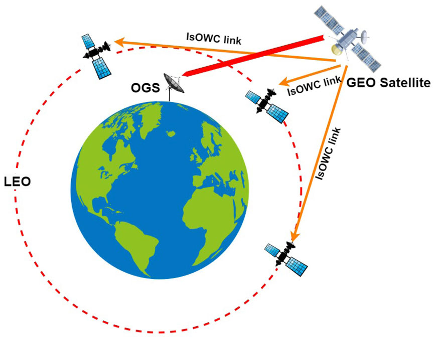
Figure 1. Application scenario of GEO-relaying between Optical ground station and LEO satellites employing inter-satellite OWC links.
The presence of eavesdropping is attributed to the inherent openness of wireless propagation. There are various methodologies to enhance the security of OWC communication. User links may be vulnerable to drone-based interception because of the fast movement of LEO satellites in optical wireless communications. Mitigation options encompass the utilization of Direct Sequence Spread Spectrum and physical layer security approaches, as documented in Refs. [22–24]. The attainment of confidentiality in satellite communication systems necessitates making certain trade-offs. Efforts aimed at improving uplink confidentiality often require the reduction of transmit power, thereby affecting the integrity of the system. On the other hand, amplifying transmit power to enhance link reliability results in a higher likelihood of eavesdropping, as indicated by previous research [25]. Li et al. in [26] assessed security performance, focusing on eavesdropping attacks and proposing a physical layer security-based satellite communication solution. Han et al in [27] used relays with hopped beams to protect the Satellite Identification Number from uplink jamming and downlink eavesdropping. Li et al. in [28] investigated integrating artificial intelligence and blockchain to improve data security in 6G, tackling eavesdropping and malicious message modification. Wang et al. in [29] noted that satellite networks merging with terrestrial networks are vulnerable to security and eavesdropping issues. They presented MIMO antenna-aided physical layer security methods to improve security and reliability due to spectrum shortages using cognitive radio approaches.
Many countries have launched mega-constellation programs, deploying thousands of optical satellites to create advanced communication networks. Huawei, for example, is planning a 10,000-satellite Low Earth Orbit (LEO) constellation called Massive VLEO, aimed at supporting beyond 5G technologies [30]. Telesat has developed a global network of 198 sophisticated LEO satellites, seamlessly integrated with terrestrial data infrastructure. Meanwhile, SpaceX is working on an extensive low-orbit satellite system designed to form a vast constellation. OneWeb is building a network of 648 LEO satellites, and Kaskilo is establishing its own constellation with 288 satellites [31]. These satellite-based optical communication networks are emerging as a key backbone for next-generation connectivity, surpassing 5G and 6G, and ensuring seamless integration between terrestrial and space-based networks. Several satellite systems using laser communications are already in operation. One notable example is a lunar laser communication experiment that successfully transmitted a Pulse Position Modulation (PPM) signal over a distance of more than 400,000 km, achieving a downlink rate of 622 Mbps and an uplink rate of 20 Mbps [32]. The Japanese Data Relay System has implemented a 1.8 Gbps inter-satellite laser communication link using DPSK/IMDD to transfer data between LEO satellites and relay satellites [33]. Similarly, the European Space Agency deployed a next-generation data relay satellite in geosynchronous orbit (36,000 km), operating with BPSK modulation at 1.8 Gbps [34]. Additionally, a 10 Gbps satellite utilizing QPSK modulation was successfully launched, enabling high-speed optical communication between the satellite and a ground station [35].
This work presents a novel data transmission technique designed for enhanced security, bandwidth efficiency, and minimal implementation complexity within existing OWC links. The proposed technique leverages a hybrid modulation scheme, combining PPM and DPSK. In PPM, data is encoded by varying the position of a pulse within a defined time slot (bit period), inherently increasing eavesdropping difficulty. DPSK, on the other hand, modulates the carrier signal’s phase by specific increments to represent data bits, further complicating unauthorized signal decoding. The combined application of PPM and DPSK renders the proposed technique relatively more secure for OWC data transmission. This heightened security stems from the requirement for an attacker to simultaneously access all three information channels embedded within the signal for successful decoding. OWC systems are inherently susceptible to eavesdropping due to the readily intercepted nature of the optical wireless signal. However, the proposed hybrid DPSK-PPM technique significantly impedes unauthorized interception or eavesdropping, thereby improving data confidentiality. This technique finds particular utility within the context of GEO data relaying, enabling the transmission of multiple channels with enhanced security and bandwidth efficiency, as exemplified in the application scenario depicted in Figure 1. The composite optical signal, carrying information from three distinct channels, is transmitted towards the GEO satellite. Functioning as a relay between an OGS and three LEO satellites, the GEO satellite separates each channel before forwarding them to their respective LEO satellite destinations. By transmitting three independent channels through a single OWC link, the proposed method fosters increased efficiency within OWC systems by minimizing the number of required optical transceivers. Notably, the stationary nature of the GEO satellite grants it a significantly larger coverage area compared to the constantly moving LEO satellites. The subsequent section delves into the intricacies of the proposed technique and the simulation setup employed to generate the results.
3 Proposed architecture
Figure 2 illustrates the detailed configuration of the proposed technique. The system employs a pulsed laser source operating at a central wavelength of 1,552 nm. This laser generates Gaussian pulses with a pulse width of 12 ps and a repetition rate of 10 GHz. These pulses serve as carriers for data from three channels originating at the OGS. Each data symbol encompasses three data bits. For channel one, data encoding is achieved using Optical DPSK modulation. Initially, a pseudo-random bit sequence (PRBS) generator creates a bitstream that is subsequently fed into a DPSK encoder. Within the DPSK encoder, the PRBS data undergoes a one-bit delay via an Exclusive-OR gate before conversion into Non-Return-to-Zero (NRZ) format. The DPSK-encoded electrical signal then modulates a Mach-Zehnder modulator (MZM), generating an optical DPSK signal. Consequently, the optical DPSK signal encodes the data bits for channel one efficiently within the phase of the optical carrier [36].
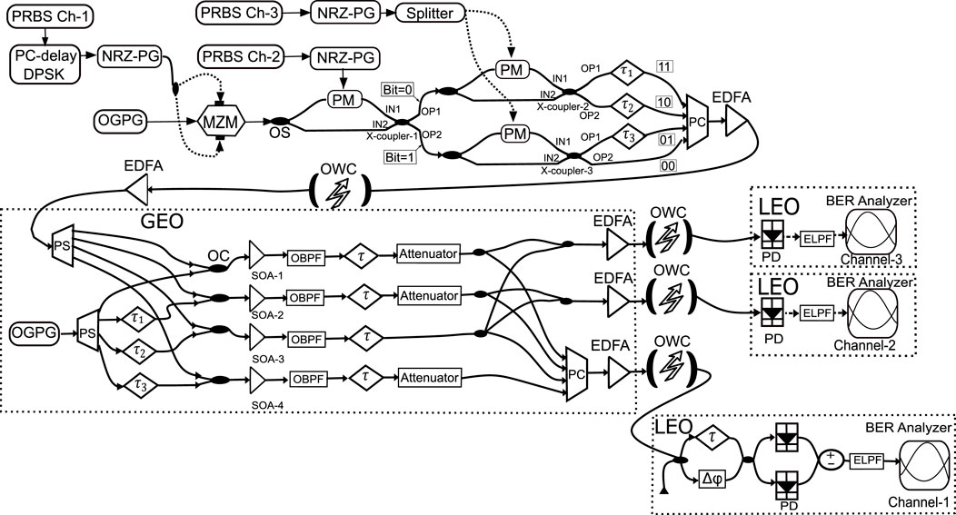
Figure 2. Hybrid PPM-DPSK technique designed in Optisystem. EDFA: Erbium doped fiber amplifier, PM: Phase modulator, PC: Power combiner, OC: Optical coupler, OS: Optical splitter, PS: Power splitter, PD: Photodetector, OBPF: Optical band pass filter, OGPG: Optical Gaussian pulse generator, ELPF: Electrical low pass filter. SOA: Semiconductor optical amplifier.
Following its generation, the optical signal is directed through a Mach-Zehnder Interferometer (MZI) structure. One arm of the interferometer incorporates a phase modulator (PM) that receives its electrical input signal from channel two, possessing a data rate of 10 Gbps. The data for channel two is generated by a PRBS generator, which subsequently controls a NRZ electrical pulse generator. When a high electrical data value (representing a “1” bit) is applied, the PM induces a 90-degree rotation in the phase of the optical signal. Conversely, the phase remains unaltered for 0 bits (“0”). Finally, a 3 dB coupler, featuring two input and two output ports, is positioned at the MZI’s output [39]. The X-coupler has a transfer function that can be written as Equation 1 below:
The transfer matrix of the MZI determines the output port of the optical signal. When the phase undergoes a 90-degree shift, the signal emerges from port OP1 of the 3 dB coupler. Conversely, if the phase remains unchanged, the signal exits through port OP2. In essence, the data bits of channel one dictate the propagation path of the optical signal within the MZI. This is because the phase modulation applied by the PM, controlled by channel two’s data, directly influences the phase shift experienced by the signal.
Subsequent to the initial MZI stage, two additional MZIs are employed. The PMs within these MZIs receive electrical data pulses from channel three simultaneously. Similar to the first MZI, the PM controlled by channel two’s data dictates the output port of the 3 dB couplers (X-couplers) that the optical signal will traverse. A “1” bit from channel two’s PM directs the signal to port OP1, while a “0” bit routes it to port OP2. Consequently, each of the four output ports from X-coupler-2 and X-coupler-3 will receive an optical pulse within each time period, determined by the data bits processed by the respective MZIs’ PMs. Variable delay lines are then introduced to implement PPM for four distinct bit combinations on the output paths. Each pair of data bits (“2-bit symbol”) governs the position of a pulse within a fixed time frame. The pulse corresponding to the bit pair “00” experiences no delay. The pulse for the bit pair “01” incurs the smallest delay (t1), exceeding the optical signal’s pulse width (12 ps). Conversely, the pulse for the bit pair “11” has the largest delay (t3), yet remains shorter than the optical signal’s time period (100 ps). The bit pair “10” experiences a delay (t2) with a value between t1 and t3. A 4 × 1 power combiner subsequently merges the four outputs. The power combiner’s output is then amplified by an Erbium-doped Fiber Amplifier (EDFA) before being transmitted over the OWC originating from the OGS. The Gamma-Gamma channel model under medium turbulence conditions [36] is employed to simulate the characteristics of this channel. The Gamma-Gamma model accounts for both by modelling turbulence as the product of two independent Gamma-distributed random variables, one for small-scale turbulence and the other for large-scale turbulence. This makes it more general than simpler models like log-normal (valid only for weak turbulence) or exponential (used for deep fading). Furthermore, the Gamma-Gamma model provides a good fit to experimental results over a wide range of turbulence conditions, from weak to strong turbulence regimes [36].
The optical channel in our simulation setup is composed of three components that are transmitter telescope, optical communication link and the receiver telescope. The power of the optical signal
In Equation 2 above,
and
In the above expressions,
and
where,
Upon reaching the GEO satellite relay, the received optical signal is separated into four distinct paths using a power splitter. Here, an optical pump signal comes into play. Similar to the pulsed laser source at the ground station, it employs a different optical wavelength of 1,550 nm. This pump signal serves to demodulate the received DPSK-PPM signal and recover the embedded data channels. The four signals generated by the local pump source are intentionally delayed using the same delay values implemented at the transmitter side. This ensures that a single pump pulse consistently coincides with each PPM pulse time interval as input to the Semiconductor Optical Amplifiers (SOAs) depicted in Figure 2. Each of the four paths experiences a random combination with the four received signals, and subsequently undergoes Four-Wave Mixing (FWM) within the SOAs. The pump power and the wavelength difference between the pump and signal pulses are carefully selected to generate a sideband on each side of the combined signal and pump spectrum [8]. Bandpass filters centered at 1548.4 nm are positioned after each SOA to selectively extract the desired FWM sidebands.
As previously discussed, each PPM pulse encodes two data bits simultaneously, one each for channels two and three (refer to Figure 3). The specific bit combination determines the observable FWM sideband after the Optical Bandpass Filters (OBPFs). For instance, the bit pair “11” is transmitted with a delay of t3. This pulse will only effectively interact with the pump pulse entering SOA-3, which possesses the same delay. The resulting FWM sideband generated at SOA-3 is then filtered, delayed, and equally divided between the photodetectors designated for channels two and three. Consequently, a PPM pulse representing the “11” bit pair splits into two On-Off Keying (OOK) pulses, each conveying a “1” bit. Time delays are strategically introduced at the output of all OBPFs to ensure proper alignment of pulses across all paths. Following a similar principle, the bit pair “10” experiences a transmission delay of t2. On the receiver side, this pulse interacts solely with the local pulse at SOA-2 that shares the same delay. As a result, FWM sideband generation is exclusive to SOA-2. After filtering and delay adjustments, the output is directed solely to the photodetector dedicated to channel one. This translates to channel one receiving a pulse signifying a “1” bit, while channel two receives no pulse, signifying a “0” bit. Subsequently, the pulse undergoes further delay and attenuation to synchronize with pulses in other paths. By following this procedure, a pulse representing the “01” bits is delivered exclusively to the photodetector of channel three. For the bit pair “00,” no overlap occurs within the SOA due to the absence of a received pulse. Consequently, no pulse appears at the output of the OBPFs. Both receivers interpret this absence of an optical pulse as a “0” bit. In essence, this conversion method effectively transforms the received PPM signal into two independent OOK signals. The OOK signals detected by the photodetectors are then processed through low-pass filters to eliminate noise. The resulting signals are subsequently fed into a Bit Error Rate (BER) analyzer for computation using eye diagrams, as explained in the following section.
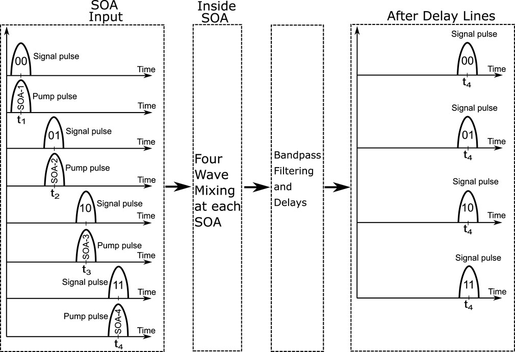
Figure 3. Explanation of Pulse Position demodulation using pump pulses.
Based upon the findings presented in [40], our approach leverages a SOA for signal processing. When the received signal and the local pump signal are introduced into the SOA, idler signals are generated. The wavelengths of these idler signals are directly dependent on the spacing between the original signals. The primary factor influencing the amount of idler signals produced within the SOA is the combination of received and pump signal powers, along with their respective wavelengths [40]. Notably, the efficiency of FWM exhibits an inverse relationship with the wavelength spacing between the parent signals. Consequently, we meticulously adjust the signal strength and wavelength separation to ensure the generation of only one idler signal on each side of the spectrum. The resulting combined signal is then transmitted over the IsOWC to the third LEO satellite equipped with a DPSK receiver. The incoming optical DPSK signal undergoes demodulation using a balanced detection technique. This method capitalizes on the relative phase shifts experienced between consecutive data bits. A bit delay introduced by the Mach-Zehnder Delay-Interferometer serves as a reference signal. This reference signal effectively cancels out the phase information incorporated during the modulation process [41, 42]. The photodiodes convert the remaining intensity difference, reflecting the phase change between bits, into electrical currents. The DPSK decoder then compares the current difference at bit transitions to identify data bit flips, thereby recovering the original data stream. This process essentially removes the bit-delay signal and decodes the transmitted information [41, 42]. Through this approach, we achieve successful reception and decoding of data bits from all three channels on the LEO satellites. The simulation incorporates various parameters, including the characteristics of the optical pulsed laser source, such as its center wavelength, pulse width, and repetition rate. Consistent values are employed for both communication links, encompassing aperture diameter, input power to the OWC, transmitter/receiver geometric parameters, pointing error angles, optical component’s efficiency and the extinction ratio of the Mach-Zehnder modulator. A table summarizing the key simulation parameters used in the proposed model is presented in Table 1.
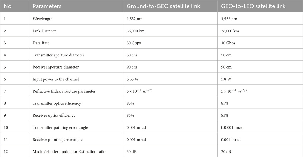
Table 1. List of parameters applied in the proposed model.
4 Results and discussion
As mentioned earlier, this work proposes a novel technique that achieves a combined transmission rate of 30 Gbps. Each of the three independent channels carries data at a rate of 10 Gbps, utilizing a single pulsed laser source with a repetition rate of 10 GHz. To evaluate the effectiveness of the proposed method, the BER for each channel was analyzed across varying received optical signal powers. The widely adopted Gamma-Gamma model was employed to characterize the OWC channel. In this model, a scintillation index of
As described earlier, the receiver employs FWM within the SOAs to convert the received DPSK + PPM signal into separate OOK signals representing channels one, two and three. Figures 4A–D showcases the optical spectra observed at the output of each SOA. The spectral plots reveal that the received optical signal and pump signal are centered at wavelengths of 1,552 nm and 1,550 nm, respectively. The FWM process generates two major sidebands surrounding these central wavelengths, specifically located at 1,548 nm and 1,554 nm. As noted in [40], nonlinear effects within the SOAs introduce a slight shift in the sideband wavelengths. Using OBPFs with a 40 GHz bandwidth centered at 1548.4 nm, the sideband closer to the pump wavelength is selectively chosen. Figure 4E presents an eye diagram of the received hybrid DPSK-PPM signal. This eye diagram demonstrates that the optical pulses occupy four distinct positions within a single bit period. Each position in this context represents a two-bit combination. The optical pulses are delayed based upon the two-bit combination. For example, the bit combination of “00” will result in no delay of the pulse. If
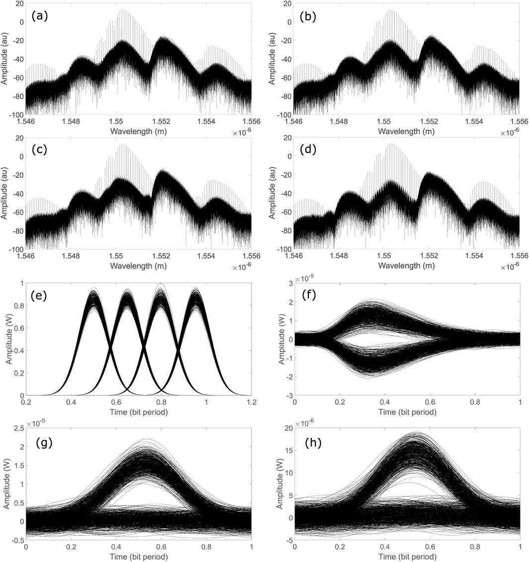
Figure 4. Optical spectra of the signals at the output of (A) SOA-1, (B) SOA-2, (C) SOA-3 and (D) SOA-4. (E) Eye diagram of the combined signal received at the GEO satellite before demodulation. Eye diagrams of the demodulated signals for (F) Channel-1, (G) Channel-2 and (H) Channel-3, respectively.
Figure 5 shows the BER performance of the three channels for different values of received optical powers. Furthermore, the BERs are measured for two different values of the time delay
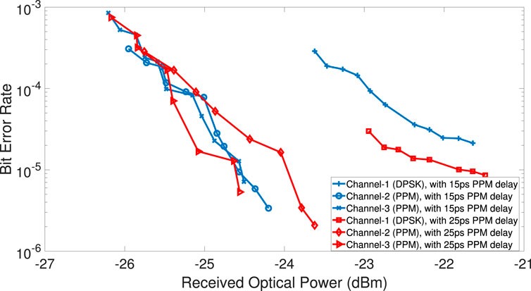
Figure 5. BER versus received optical power for all three channels and two different PPM delays.
A comparison among different modulation formats employed in our work, that are PPM and DQPSK and the commonly employed formats, that are OOK and quadrature phase shift keying (QPSK) has been presented in Table. 2. Based on this comparison, it may concluded that a hybrid modulation scheme that combines PPM and DPSK (PPM-DPSK) can leverage the advantages of both techniques, leading to improved performance in power-limited and bandwidth-constrained optical communication systems. The transmission of multiple data streams can be achieved using techniques such as Wavelength Division Multiplexing (WDM) with three signals or PAM-8 modulation; however, these approaches introduce higher complexity. In contrast, our technique utilizes only off-the-shelf components, making it more practical and cost-effective. Additionally, the SOA employed in our approach is a low-power device that can be seamlessly integrated on-chip, enhancing scalability and efficiency. While synchronization challenges exist, they are common across various modulation schemes. Standard synchronization mechanisms can be applied to mitigate these issues effectively. Various approaches can be utilized to extend the proposed scheme for transmission up to 100 Gbps. For instance, the data rate can be increased by introducing additional wavelengths or reducing pulse widths to enhance temporal resolution. Our technique leverages off-the-shelf components and can be seamlessly integrated into existing deep-space communication links that currently employ OOK or DPSK, ensuring compatibility with deployed infrastructure while offering enhanced performance.
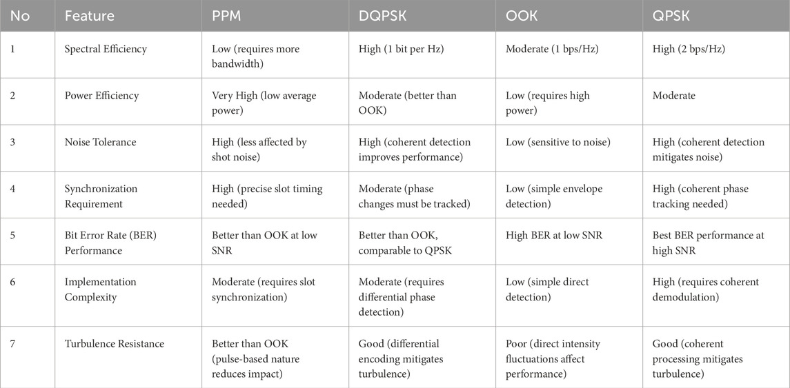
Table 2. Comparison among different modulation formats.
5 Conclusion and future work
This work presents a novel technique for transmitting three secure data channels over a single OWC link. This approach addresses the limitations of traditional methods by combining the security benefits of DPSK with the flexibility of PPM. By offering a selection of time delay values between PPM pulses, the method enhances the security of OWC links against eavesdropping, providing a dynamic and adaptable security mechanism. Compared to conventional techniques like OOK and DPSK only, our proposed method transmits data from three distinct channels using a single optical carrier, resulting in reduced power consumption per channel. Additionally, the technique facilitates uplink data transmission from the OGS to multiple LEO satellites via a GEO data relay satellite, improving overall link availability. The cost-effectiveness of this method lies in its ability to be implemented without requiring specialized components, making it a practical solution for network operators. This innovative approach has the potential to revolutionize wireless connectivity by enabling widespread networks that leverage both terrestrial and satellite-based optical connections. Potential applications include underwater communication networks and high-speed internet access in remote locations. Given the ever-increasing demand for secure and high-speed communication, this method holds significant promise for real-world deployment.
Data availability statement
The original contributions presented in the study are included in the article/supplementary material, further inquiries can be directed to the corresponding authors.
Author contributions
CX: Software, Writing–original draft. UK: Software, Validation, Writing–review and editing. SG: Conceptualization, Methodology, Writing–review and editing. JM: Resources, Writing–review and editing, Project administration. AA: Supervision, Writing–review and editing. IA: Funding acquisition, Writing–review and editing.
Funding
The author(s) declare that no financial support was received for the research, authorship, and/or publication of this article.
Conflict of interest
The authors declare that the research was conducted in the absence of any commercial or financial relationships that could be construed as a potential conflict of interest.
Generative AI statement
The author(s) declare that no Generative AI was used in the creation of this manuscript.
Publisher’s note
All claims expressed in this article are solely those of the authors and do not necessarily represent those of their affiliated organizations, or those of the publisher, the editors and the reviewers. Any product that may be evaluated in this article, or claim that may be made by its manufacturer, is not guaranteed or endorsed by the publisher.
References
1. Mohsan SAH, Mazinani A, Sadiq HB, Amjad H. A survey of optical wireless technologies: practical considerations, impairments, security issues and future research directions. Opt Quant Electron (2022) 54:187. doi:10.1007/s11082-021-03442-5
2. Khan MS, Ghafoor S, Mirza J, Hassan Zaidi SM. Review of studies that integrate the free space optics with fiber optics. In: 2019 IEEE 16th international conference on smart cities: improving quality of life using ICT and IoT and AI (HONET-ICT). Charlotte, NC, USA (2019). p. 074–9.
3. Chowdhury MZ, Hossan MT, Islam A, Jang YM. A comparative survey of optical wireless technologies: architectures and applications. IEEE Access (2018) 6:9819–40. doi:10.1109/access.2018.2792419
4. Bhutani M, Lall B, Agrawal M. Optical wireless communications: research challenges for MAC layer. IEEE Access (2022) 10:126969–89. doi:10.1109/access.2022.3225913
5. Morthier G, Roelkens G, Baets R. Optical versus RF free-space signal transmission: a comparison of optical and RF receivers based on noise equivalent power and signal-to-noise ratio. IEEE J Sel Top Quan Electron. (2022) 28(2):1–8. doi:10.1109/jstqe.2021.3129250
6. Mohsan SAH, Amjad H. A comprehensive survey on hybrid wireless networks: practical considerations, challenges, applications and research directions. Opt Quant Electron (2021) 53:523. doi:10.1007/s11082-021-03141-1
7. Chow C-W, Yeh C-H, Liu Y. Optical wireless communications (OWC) - technologies and applications. In: 2020 opto-electronics and communications conference (OECC). Taipei, Taiwan (2020). p. 1–3.
8. Morra AE, Ahmed K, Hranilovic S. Impact of fiber nonlinearity on 5G backhauling via mixed FSO/fiber network. IEEE Access (2017) 5:19942–50. doi:10.1109/access.2017.2753178
9. Elamassie M, Uysal M. Statistical characterization of FSO-based airborne backhaul links. In: 2023 international balkan conference on communications and networking (BalkanCom). Turkiye: Istanbul (2023). p. 1–6.
10. Zhou G, Zhou X, Li W, Zhao D, Song B, Xu C, et al. Development of a lightweight single-band bathymetric LiDAR. Remote Sens (2022) 14:5880. doi:10.3390/rs14225880
11. Wang L, Fu Q, Zhu R, Liu N, Shi H, Liu Z, et al. Research on high precision localization of space target with multi-sensor association. Opt Lasers Eng (2025) 184(Part 1):108553. 0143-8166. doi:10.1016/j.optlaseng.2024.108553
12. Dong Y, Li W, Zhang J, Luo W, Fu H, Xing X, et al. High-speed PGC demodulation model and method with subnanometer displacement resolution in a fiber-optic micro-probe laser interferometer. Photon Res (2024) 12:921–31. doi:10.1364/prj.513576
13. Rose TS, Rowen DW, Coffman CM, Kinum G, LaLumondiere S, Werner NI, et al. Optical downlink and intersatellite illumination experiments with low-earth orbiting cubesats, Free-Space Laser Commun XXXII. 11272. (2020). p. 369–74. doi:10.1117/12.2554958
14. Perlot N, de Cola T. Throughput maximization of optical LEO-ground links. In: Proc. SPIE (2012).
15. Zhang W, Yang G, Jiang F, Zhao K, Wang J, Li W, et al. Licklider transmission protocol for GEO-relayed space internetworking. Wireless Netw (2018) 25(7):3747–57. doi:10.1007/s11276-018-1669-4
16. Zech H, Heine F, Tröndle D, Seel S, Motzigemba M, Meyer R, et al. LCT for EDRS: LEO to GEO optical communications at 1,8 Gbps between alphasat and sentinel 1a. Proc SPIE (2015) 9647:96470J. doi:10.1117/12.2196273
17. Edwards B, Randazzo T, Babu N, Murphy K, Albright S, Cummings N. Challenges, lessons learned, and methodologies from the LCRD optical communication system AI&T. In: Proc. IEEE int. Conf. Space opt. Syst. Appl. (2022). p. 22–31. doi:10.1109/ICSOS53063.2022.9749730
18. Yamakawa S, Satoh Y, Itahashi T, Takano Y, Hoshi S, Miyamoto Y. LUCAS: the second-generation GEO satellitebased space data-relay system using optical link. In: Proc. IEEE int. Conf. Space opt. Syst. Appl. (2022). p. 14–6. doi:10.1109/ICSOS53063.2022.9749726
19. Tawfik MM, Sree MFA, Abaza M, Ghouz HHM. Performance analysis and evaluation of inter-satellite optical wireless communication system (IsOWC) from GEO to LEO at range 45000 km. IEEE Photon J (2021) 13(4):1–6. doi:10.1109/jphot.2021.3104819
20. Gunawan WH, Chow CW, Liu Y, Chang YH, Jian YH, Peng CW, et al. Digital domain power division multiplexing optical OFDM for free space optical communication (FSOC) using 10- GHz bandwidth optical components. IEEE Photon J (2022) 14(4):1–7. doi:10.1109/jphot.2022.3182867
21. Kiasaleh. Performance of APD-based PPM free-space optical communication systems in atmospheric turbulence. IEEE Trans Commun (2005) 53(9):1455–61. doi:10.1109/TCOMM.2005.855009
22. Dong F, Wang W, Li X, Liu F, Chen S, Hanzo L. Joint beamforming design for dual-functional MIMO radar and communication systems guaranteeing physical layer security. IEEE Trans Green Commun Netw (2023) 7(1):537–49. doi:10.1109/tgcn.2022.3233863
23. Lu Z, Jiao Y. Efficiently all-digital code tracking for band-limited DSSS systems. IEEE Commun Lett (2023) 27(2):686–90. doi:10.1109/lcomm.2022.3222296
24. Wang F, Cui W, Tian J. A super-resolution multipath estimation algorithm for DSSS systems. IEEE Trans Aerosp Electron Syst (2023) 59(1):109–24. doi:10.1109/taes.2022.3188237
25. Zou Y, Zhu J, Li X, Hanzo L Relay selection for wireless communications against eavesdropping: a security-reliability trade-off perspective. IEEE Netw (2016) 30(5):74–9.
26. Li B, Fei Z, Zhou C, Zhang Y. Physical-layer security in space information networks: a survey. IEEE Internet Things J (2020) 7(1):33–52. doi:10.1109/jiot.2019.2943900
27. Han R, Bai L, Jiang C, Liu J, Choi J. A secure architecture of relay-aided space information networks. IEEE Netw (2021) 35(4):88–94. doi:10.1109/mnet.011.2100076
28. Li W, Su Z, Li R, Zhang K, Wang Y. Blockchain-based data security for artificial intelligence applications in 6G networks. IEEE Netw (2020) 34(6):31–7. doi:10.1109/mnet.021.1900629
29. Wang P, Zhang J, Zhang X, Yan Z, Evans BG, Wang W. Convergence of satellite and terrestrial networks: a comprehensive survey. IEEE Access (2019) 8:5550–88. doi:10.1109/access.2019.2963223
30. Tong W. A perspective of wireless innovations in the next decade. In: IEEE globecom keynote session. Abu Dhabi, UAE (2018).
31. del Portillo I, Cameron BG, Crawley EF. A technical comparison of three low earth orbit satellite constellation systems to provide global broadband. Acta Astronaut. (2019) 159:123–35. doi:10.1016/J.ACTAASTRO.2019.03.040
32. Boroson DM, Scozzafava JJ, Murphy DV, Robinson BS, Lincoln MIT. The lunar laser communications demonstration (LLCD). In: ICSOS. Pasadena, CA, USA (2009). p. 23–8.
33. Satoh Y, Miyamoto Y, Takano Y, Yamakawa S, Kohata H. Current status of Japanese optical data relay system (JDRS). ICSOS, Naha, Jpn (2017) 240–2. doi:10.1109/ICSOS.2017.8357398
34. Poncet D, Glynn S, Heine F. Hosting the first EDRS payload. In: ICSO, canary islands (2014). p. 97–105. Spain.
35. Yue C, Yong T. All in-orbit core tests of Practice 20 satellite completed. Space Int (2020) 7:38–41. doi:10.3969/j.issn.1009-2366.2020.07.010
36. Bekkali A, Fujita H, Hattori M. New generation free-space optical communication systems with advanced optical beam stabilizer. IEEE J Lightwave Technology (2022) 40(5):1509–18. doi:10.1109/jlt.2022.3146252
37. Polishuk A, Arnon S. Optimization of a laser satellite communication system with an optical preamplifier. J Opt Soc Am A (2004) 21:1307–15. doi:10.1364/josaa.21.001307
38. Arnon S. Performance of a laser satellite network with an optical preamplifier. J Opt Soc Am A (2005) 22:708–15. doi:10.1364/josaa.22.000708
40. Baveja PP, Maywar DN, Agrawal GP. Interband four-wave mixing in semiconductor optical amplifiers with ASE-enhanced gain recovery. IEEE J Selected Top Quan Electronics (2012) 18(2):899–908. doi:10.1109/jstqe.2011.2136372
41. Alipour A, Farmani A, Mir A. Analysis of optical power budget in DWDM-FSO link under outdoor atmospheric channel model. Opt Quan Electronics (2021) 53(8):446. doi:10.1007/s11082-021-03112-6
Keywords: free space optical communication, inter-satellite optical wireless communication, pulse position modulation, differential phase shift keying, low earth orbit (LEO), geostationary Earth orbit (GEO)
Citation: Xu C, Khan UA, Ghafoor S, Mirza J, Aljohani AJ and Aziz I (2025) A ground-to-GEO-to-LEO satellite optical wireless communication link based on a spectrally efficient and secure modulation scheme. Front. Phys. 13:1562799. doi: 10.3389/fphy.2025.1562799
Received: 18 January 2025; Accepted: 21 February 2025;
Published: 10 March 2025.
Edited by:
Sushank Chaudhary, Chulalongkorn University, ThailandReviewed by:
A. K. M. Sharoar Jahan Choyon, University of New Mexico, United StatesAbhishek Sharma, National Institute of Technology, Hamirpur, India
Copyright © 2025 Xu, Khan, Ghafoor, Mirza, Aljohani and Aziz. This is an open-access article distributed under the terms of the Creative Commons Attribution License (CC BY). The use, distribution or reproduction in other forums is permitted, provided the original author(s) and the copyright owner(s) are credited and that the original publication in this journal is cited, in accordance with accepted academic practice. No use, distribution or reproduction is permitted which does not comply with these terms.
*Correspondence: Imran Aziz, aW1yYW4uYXppekBwaHlzaWNzLnV1LnNl; Chen Xu, eHVjaGVuLXh1QG91dGxvb2suY29t