Stress concentration of perforated cement sheath and the effect of cement sheath elastic parameters on its integrity failure during shale gas fracturing
- 1School of Petroleum Engineering, China University of Petroleum (East China), Qingdao, China
- 2Key Laboratory of Unconventional Oil and Gas Development, China University of Petroleum (East China), Ministry of Education, Qingdao, China
- 3Key Laboratory of Unconventional Natural Gas Evaluation and Development in Complex Tectonic Areas, Ministry of Natural Resources, Guiyang, China
- 4Guizhou Engineering Research Institute of Oil and Gas Exploration and Development, Guiyang, China
- 5Cementing Company, SINOPEC Zhongyuan Oilfield Service Corporation, Beijing, China
Due to the extremely low porosity and permeability of shale, fracturing is often used to develop shale gas reservoirs. During shale fracturing, extremely high fracturing pressure may invalidate the integrity of the cement sheath and bring hidden dangers to the safe development of shale gas. This paper compares the stress state of the three-dimensional unperforated and perforated finite element models of casing-cement sheath-formation to obtain the influence of perforation on the stress concentration and failure area of the cement sheath. The stress state comparison incorporates three sets of perforation models with different hole densities and diameter verifies the stress concentration law of perforation on the cement sheath. By studying the effects of the elastic modulus and Poisson’s ratio of the cement sheath on the maximum tensile and compressive stresses of the cement sheath under fracturing pressure, the integrity failure form of the cement sheath and the measures for integrity failure are obtained. The results show that the peak stress concentration of the perforated cement sheath is about twice the normal value of the stress. The failure area is the two ends of the perforation, the shape is similar to the bottom surface of the elliptical cone, and the thickness is up to half of the wall thickness of the cement sheath. The line length of the largest failure area is 4.5 times the diameter of the hole. Under fracturing conditions, the cement sheath generally undergoes tensile failure. The lower the elastic modulus and Poisson’s ratio of the cement sheath, the smaller the tensile stress of the cement sheath, and the less likely it is to cause tensile failure.
1 Introduction
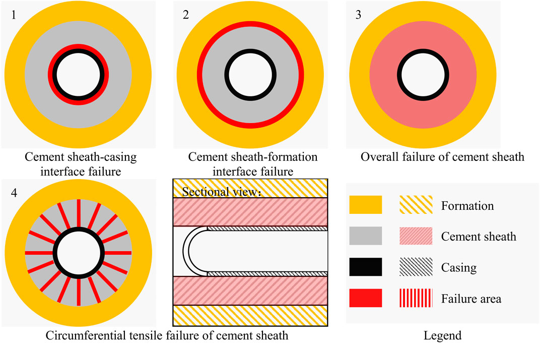
The porosity and permeability of shale are extremely low, and volume fracturing is often used to develop shale gas reservoirs (Guo et al., 2018; Yan et al., 2018). Cementing is the last link before the development of oil and gas reservoirs. Good cementing quality can provide interlayer isolation and prevent formation fluids from migrating to the inside of the wellbore (Jiapei et al., 2018). The better the fluidity of the cement slurry, the better the quality of cementing (Wang et al., 2022). Most of the current shale gas development uses cemented casing perforation completion methods, and uses horizontal well multi-stage fracturing technology to increase production. Extremely high fracturing pressure, especially repeated fracturing, will cause cement sheath sealing integrity failure. That probably will cause significant damage to the environment, health and economy (Smith et al., 2011). The types of cement sheath integrity failures are shown in Figure 1. The failure of seal integrity of cement sheath includes circumferential tensile failure, shear failure and interface debonding (Bu et al., 2020a; Bu et al., 2020b; De Andrade and Sangesland, 2016; Guo et al., 2020; Yang et al., 2021).
Fallahzadeh and Rasouli, (2012) used the analytical equation of borehole stress distribution to numerically simulate the influence of perforation azimuth on the micro-gap of the cement sheath: when the perforation azimuth relative to the lowest point of the well is 180°, the cement sheath will produce micro-gap; When the perforation azimuth is 45° with respect to the lowest point of the well, cracks will occur somewhere in the middle of the PH(perforation hole), and there will be no micro gaps in the cement sheath. Guo (Guo et al., 2015) studied the effect of high-density perforation on casing failure using a three-dimensional FEM(finite element method). The research results show that perforation will cause uneven stress distribution in the casing, which will lead to non-uniform deformation of the casing. Wang (Wang and Taleghani, 2014) used a three-dimensional pore-elastic model of coupled bonding elements to simulate the expansion of fractures in the process of hydraulic fracturing stimulation. The result has shown that fluid leakage around the casing shoe may cause cement sheath-formation interface debonding. Lu (Lu et al., 2016) studied the effect of hydraulic fracturing of high-temperature and high-pressure wells on the failure of cement sheath by methods of experiment and finite element simulation. The results show that under long-term high pressure exposure, the microstructure of the cement sheath is damaged and its strength is reduced; in the case of hydraulic fracturing, the low elastic modulus and high Poisson’s ratio cement sheath are beneficial to maintaining the integrity of the CCF(casing-cement sheath-formation) system. Liu (Liu et al., 2018) studied the effect of casing centering and casing eccentricity on the integrity of cement sheath in the case of horizontal well hydraulic fracturing. The results of the study show that under the condition of high casing pressure, the inner wall of the cement sheath will occur tensile failure; if the casing is eccentric, SC(stress concentration) will occur at the thinnest part of the cement sheath, which is more likely to fail. Wu (Wu et al., 2019) used the FEM to study the casing integrity under hydraulic fracturing of shale formations. The results of the study show that water injection into a naturally fractured shale formation will cause limited displacement of the shale, which may further squeeze the casing and cause the casing to fail. Lian (Lian et al., 2020) used a three-dimensional finite element model to study the cement sheath-formation interface failure caused by fluid migration during shale gas hydraulic fracturing. The research results show that increasing the elastic modulus and bonding strength of the cement sheath can improve the ability of the cement sheath to resist interface failure; the perforation azimuth has little effect on the cement sheath-formation interface failure. Zhou (Zhou et al., 2019) studied the impact of fracturing on the integrity of the cement sheath in deep and shallow formations. The results show that during the fracturing process, the cement sheath of shallow layer fracturing has the risk of circumferential tensile failure; the cement sheath bonded with the deep layer has the risk of plastic failure under compression. Yin (Yin et al., 2019) studied the influence of changes in downhole temperature and pressure conditions on the cement sheath micro-gap. The results show that the debonding at the cement sheath interface occurs at the beginning of the cold water cycle; compared with the pressure, the thermal effect is the main factor affecting the crack initiation and size of the micro-gap. Yan (Yan et al., 2019,2020,2021) studied the effects of perforation and hydraulic fracturing on the failure of cement sheath. The research results show that during the perforation process, the peak position of cement sheath stress appears at the first cementing interface (cement sheath–casing string); during the perforation process, the main cracks first appear around the PH and then the mesh micro-cracks appear near the PH. These aforementioned research mainly focuses on the impact of perforation on casing failure, and there is less research on cement sheath. In addition, there are many studies on the influence of cement sheath mechanical parameters on the failure of cement sheath during fracturing, while there are few studies on the SC law caused by perforation.
In this paper, the three-dimensional unperforated and perforated finite element model of CCF is established with use of the ANSYS software and the actual wellbore structure and perforation parameters. Under the fracturing conditions, the stress distribution of the unperforated cement sheath and the PCS(perforated cement sheath) is studied. And the influence of the elastic modulus and Poisson’s ratio of the cement sheath on the cement sheath’s maximum tensile and compressive stress is studied. The effects of perforation on the stress concentration of the cement sheath and the failure of the cement sheath have been analyzed. Accordingly, some new insights such as countermeasures for the failure of PCS are obtained which can provide references for the integrity failure of the cement sheath in the case of shale gas fracturing.
2 Mechanical model of perforated cement sheath
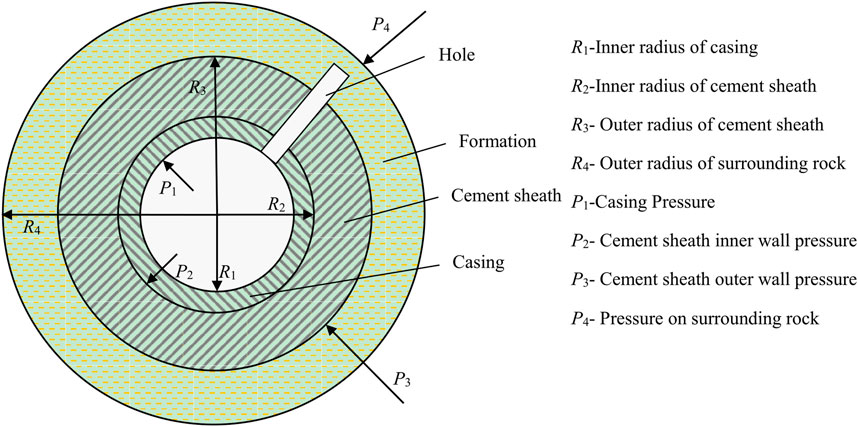
In shale gas production, casing perforation is often used to complete wells. The presence of perforations makes the geometric structure of the cement sheath asymmetrical. Therefore, the perforation model cannot be simplified to a plane strain model, which is a non-linear problem. The FEM is mostly used to solve nonlinear problems (Bois et al., 2011; Gray et al., 2009). In this paper, the FEM is used to establish and analyze the mechanical model of the PCS. Figure 2 is a schematic diagram of the mechanical model of the PCS.
The hypothesis of the PCS mechanics model is as follows:
1) Casing, cement sheath and formation are isotropic;
2) The casing and cement sheath are complete and concentric with the wellbore track;
3) The PH is regular, penetrating the casing and cement sheath in the radial direction, and penetrating into the formation.
4) The cement sheath interfaces are well cemented without gaps.
According to the principle of virtual work, the unit virtual work equation of the CCF model is:
In Eq. 1,
Derive the element stress equation according to the physical equation:
In Eq. 2,
The element stiffness matrix is:
The overall finite element equation:
In Eq. 4,
When solving the finite element equation, firstly apply appropriate displacement constraints to the model to find the displacement of each node of the model, and then put the displacement into the element stress Eq. 2 to find the strain and stress of each element.
Define the limit linear strain εjx of the cement sheath. Under triaxial stress, if the maximum linear strain ε1 of the cement sheath exceeds the limit linear strain εjx of the cement sheath, the cement sheath will crack and the fracture surface is perpendicular to ε1 (El-Sayed and Khalaf, 1992). Use the triaxial stress state principal stress σ1, σ2 and σ3 (σ1>σ2>σ3) to express the stress state as:
When σ<σjx (σjx is the equivalent stress of the second strength theory corresponding to the ultimate strain of the cement sheath), the cement sheath is safe and will not crack; when σ>σjx, the cement sheath will crack.
During fracturing, the cement sheath is mainly subjected to circumferential tensile stress, and the equivalent stress σ′ of the second strength theory (maximum elongation strain theory) of the cement sheath is (El-Sayed and Khalaf, 1992):
In the Eq. 6, σθ is the hoop stress; σr is the radial stress; σz is the axial stress.
3 Finite element model of casing-cement sheath-formation combination
3.1 Model assumptions
In order to be efficient in modeling and calculation, it is necessary to make appropriate simplification assumptions for the CCF model:
1) The well diameter is regular, the surface is smooth, and there is no collapsed block.
2) The casing, cement sheath, and wellbore have regular shapes, and the center of symmetry is the same axis.
3) The shape of the perforation tunnel is a regular cylinder, ignoring burrs and cracks, and the tunnel runs through the casing and cement sheath without dislocation. The axis of the eyelet intersects the axis of the cement sheath perpendicularly.
4) The formation is simplified, and the formation is not perforated (Philippacopoulos and Berndt, 2002; Thiercelin et al., 1998).
3.2 Finite element model
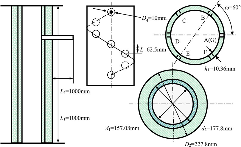
Take a well in an oil field, the vertical depth of the well is 3000m, the formation pressure gradient is 1.00 g/cm3, and the fracture pressure equivalent density is 1.76 g/cm3. The SCCK-89T perforating gun is used for perforation. The perforation radius is 10mm, the PH depth is 1000mm, the phase angle is 60o, and the hole density is 16 holes/m. The schematic diagram of perforation parameters is shown in Figure 3.
In order to eliminate the boundary effect, the formation is 10 times the diameter of the borehole (Yang et al., 2021). The geometric parameters of the model are shown in Table 1, and the material parameters are shown in Table 2 (Parameter comes from an oilfield company).
In Tables 1, 2, D1-casing outer diameter, d1-casing inner diameter, L1-casing length, D2-cement sheath outer diameter, d2-cement sheath inner diameter, L2-cement sheath length, a-formation length, b-formation width, L3-formation height, D4-PH diameter, L4-PH length, ω-perforation phase angle, n-hole density, E - elastic modulus, µ-Poisson’s ratio, ρ-density.
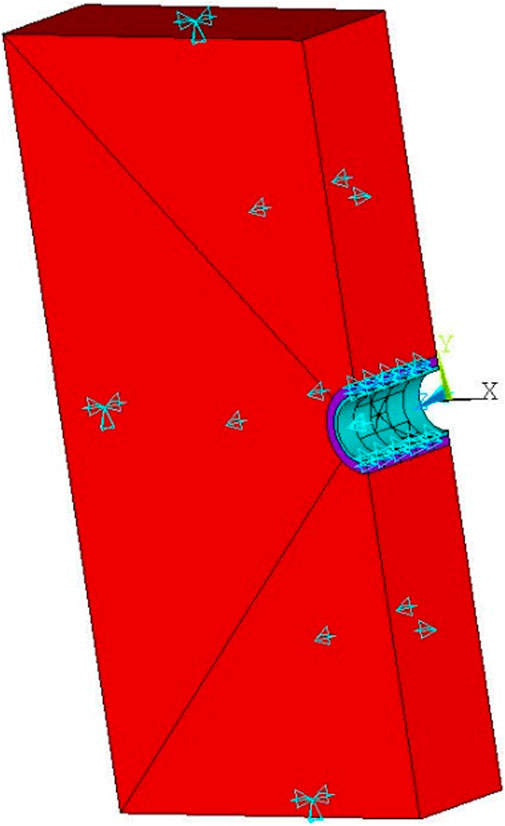
The CCF combination model is shown in Figure 4. The load and boundary conditions are shown in Figure 5. The model loads are the gravity (from the casing, the cement sheath, and the formation), the in-situ stress, and the fracturing pressure. The boundary conditions of the model are displacement constraints in corresponding directions imposed on the casing, cement sheath, and formation section.
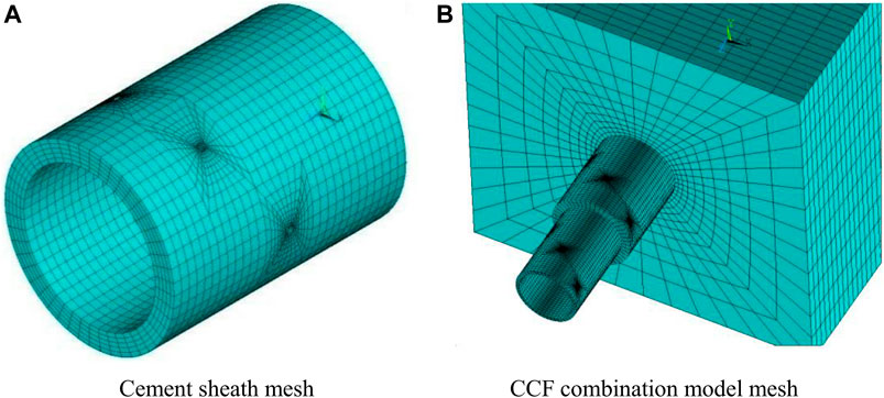
FIGURE 4. Finite element model mesh of CCF combination. (A) Cement sheath mesh. (B) CCF combination model mesh.
4 Results and discussion
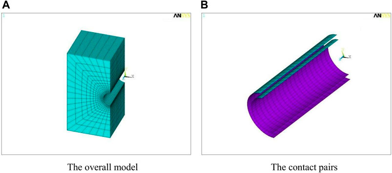
The main function of the cement sheath is to seal the formation fluid migration. The isolation effect of the cement sheath mainly relies on the integral part of the unperforated area. Therefore, when performing stress analysis on the CCF model, the effect of perforation on SC can be obtained by comparing the stress distribution of the perforated model and the unperforated model. The overall stress distribution of the cement sheath can be obtained by analyzing the unperforated model. The effect of fracturing on the SC area can be obtained by analyzing the perforated model. The overall model of the unperforated CCF 3D finite element model is shown in subfigure A of Figure 6, and the contact pairs in the model are shown in subfigure B of Figure 6.
4.1 Stress distribution of cement sheath under fracturing conditions
Under the condition of fracturing pressure of 70MPa, the stress distribution of the perforated model and the unperforated model is shown in Figure 7. It can be seen from Figure 7 that the stress distribution between the perforated model and the unperforated model is quite different. In the perforation model, the closer to the perforation area, the greater the stress. The stress at the position far from the perforation area in the perforation model is close to the stress at the corresponding position in the unperforated model. In the unperforated model, under fracturing conditions, the stress contours of the formation, casing, and cement sheath radiate outwards around the axis of the wellbore. And the stress in the unperforated model gradually decreases from the inside to the outside. The contact pressure of the cement sheath-casing interface is higher than that of the cement sheath-formation interface. The cement sheath-casing interface is in the risky state. The perforated model has a large SC phenomenon under fracturing conditions. The SC area is a rounded rectangle or ellipse. The SC phenomenon is more obvious in the place closer to the perforation area. And the stress distribution tends to be uniform in the area far from the perforation area.
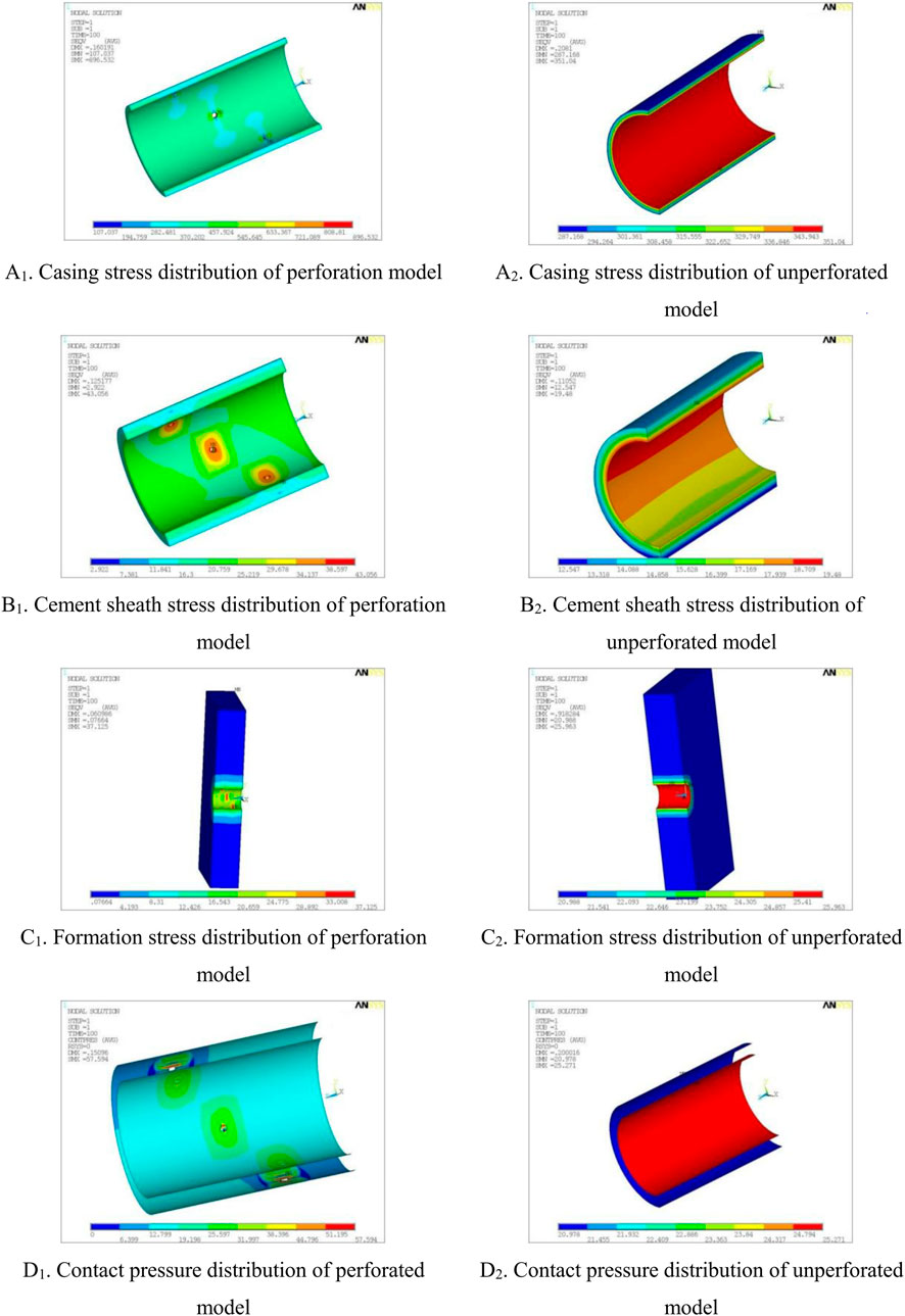
FIGURE 7. Comparison of stress distribution between perforated model and unperforated model under fracturing conditions. (A1) Casing stress distribution of prforation model. (A2) Casing stress distribution of unprforation model. (B1) Cement sheath distribution of prforation model. (B2) Cement sheath distribution of unprforation model. (C1) Formation stress distribution of prforation model. (C2) Formation stress distribution of unprforation model. (D1) Contact pressure distribution of prforation model. (D2) Contact pressure distribution of prforation model.
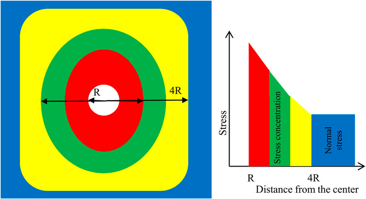
Under fracturing conditions, the displacement, stress and strain distributions of the PCS are shown in Figure 8. It can be seen from Figure 8 that the displacement, stress, and strain of the cement sheath are concentrated in the perforation area, and the concentrated area is a rounded rectangle or ellipse. The concentration phenomenon is more obvious at the place closer to the PH. The values of displacement, stress and strain tend to be smooth and stable at the place far from the PH, and the peak SC can reach more than twice the normal value. In Figure 8, the SC area is within 5 times the diameter of the PH. The distribution of SC is roughly shown in Figure 9 (taking a single hole as an example).
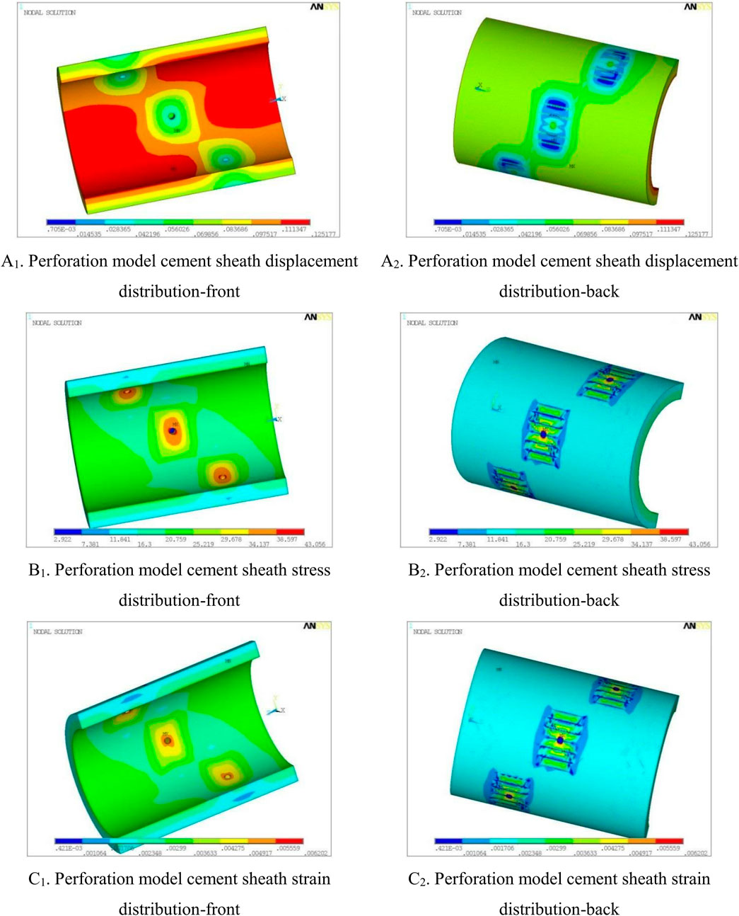
FIGURE 8. Displacement, stress and strain distribution of cement sheath in perforation model under fracturing conditions. (A1) Prforation model cement sheath displacement distribution-front. (A2) Prforation model cement sheath displacement distribution-back. (B1) Prforation model cement sheath stress distribution-front. (B2) Prforation model cement sheath stress distribution-back. (C1) Prforation model cement sheath strain distribution-front. (C2) Prforation model cement sheath strain distribution-back.
In order to verify the adaptability of the SC law of the PCS, this paper established two sets of perforating models for analysis. The first group of models selected Shengli composite 102 large-aperture perforator, hole density 25 holes/m, hole diameter 7 mm, the phase angle 60°(Luo et al., 2010); The second group of models uses the 127 type ultra-high density powder cover large-aperture perforator, the hole density 60 holes/m, the aperture 18 mm, the phase angle 60°(Fan et al., 2013), and the remaining parameters of the model remain unchanged. For different perforation models, the stress distribution of the cement sheath is shown in Figure 10.
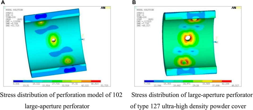
FIGURE 10. Stress distribution cloud diagram of cement sheath with different perforation models under fracturing conditions. (A) Stress distribution of perforation model of 102 large-aperture perforator. (B) Stress distribution of large-aperture perforator of type 127 ultra-high density powder cover.
Assuming that the radius of the perforation hole is R, the stress value at the PH is
The following conclusions can be drawn by comparing the perforation parameters of the three groups of perforation models:
1) Regardless of the displacement, stress, and strain, there is a big difference between the perforated area and the unperforated area. The SC area is a rounded rectangle or ellipse.
2) The SC phenomenon is more obvious at the place closer to the PH, and the value of stress and strain at the place far away from the PH tends to be smooth and stable.
3) The peak stress concentration is about twice the normal value.
4.2 Integrity failure of cement sheath and countermeasures under fracturing conditions
Due to the existence of PH, there is a SC phenomenon in the cement sheath at the PH. Larger stress values will inevitably cause damage to the cement sheath, but studies have shown that as long as most of the annular areas of the first and second interfaces of the cement sheath are not damaged, the formation will not be cross-grooved, then the cement sheath sealing is effective. Therefore, the non-perforation model is used to simulate and analyze the overall isolation performance of the cement sheath, and the perforation model is used to simulate the size of the failure area of the cement sheath.
4.2.1 The effect of elastic parameters of cement sheath on its integrity
To study the sealing effectiveness of the cement sheath, as long as the entire cement sheath is not damaged under the fracturing pressure, then cementing is effective. Keeping other parameters unchanged, the elastic modulus of the cement sheath is 1–10 GPa, and the Poisson’s ratio is 0.15–0.3. The effects of the elastic modulus and Poisson’s ratio of the cement sheath on the maximum compressive stress and maximum tensile stress is shown in Figure 11.
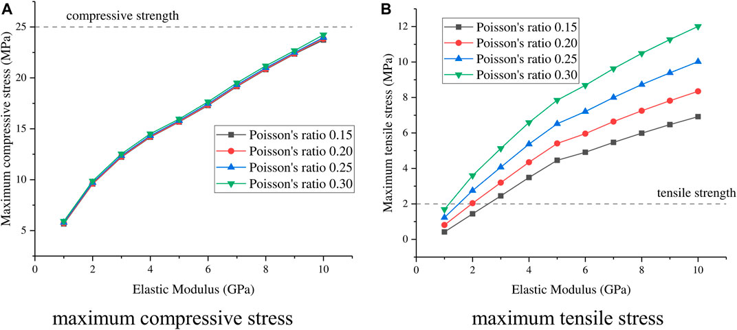
FIGURE 11. The influence of the elastic parameters of cement sheath on its maximum compressive stress and maximum tensile stress. (A) Maximum compressive stress. (B) Maximum tensile stress.
It can be seen from Figure 11 that under fracturing conditions, the Poisson’s ratio of the cement sheath has little effect on its maximum compressive stress value, and its maximum tensile stress increases with the increase of Poisson’s ratio. The maximum compressive stress and maximum tensile stress of the cement sheath increase with the increase of its elastic modulus. Under fracturing conditions, the cement sheath generally undergoes tensile failure. (Cement sheath is a brittle material, and its tensile strength is much lower than the compressive strength, generally 1/10 to 1/12 of the compressive strength (25-40 MPa), that is, the tensile strength is generally about 2-4 MPa(Yao et al., 2005).) For safety, the compressive strength in Figure 11 is 25MPa, and the tensile strength is 2 MPa. Increasing the tensile strength of the cement sheath, reducing its elastic modulus and Poisson’s ratio can effectively prevent its tensile failure.
4.2.2 Failure area of perforated cement sheath
Because of the PH, the PCS inevitably has a large SC phenomenon at the perforation area, so the cement sheath is most prone to fail at the perforation area. Under triaxial stress, if the maximum linear strain of the cement sheath exceeds the limit linear strain of the cement sheath, the cement sheath will fracture, and the fracture surface is perpendicular to the direction of the maximum principal stress (El-Sayed and Khalaf, 1992). Taking the 0.3% linear strain as the critical point of tensile failure of the cement sheath (Shen, 2011), the failure area of the cement sheath in the CCF perforation model is analyzed based on this.
With cement sheath µ = 0.15, E = 3.17 GPa and other parameters kept unchanged, the area where the cement sheath is damaged is simulated and calculated. The tensile stress and strain distribution near the PH are shown in Figure 12. In Figure 12E, the yellow and red areas are the failure areas of the cement sheath. It can be seen from Figure 12 that the failure area of the cement sheath locates at the two ends of the hole, and the shape is similar to a cone with an elliptical bottom. The maximum failure thickness is close to 1/2 of the wall thickness of the cement sheath. The line length of the largest failure area is close to 4.5 times the diameter of the hole. Since the failure areas of the holes are not connected to each other and do not affect the integrity of the cement sheath as a whole, the sealing of the cement sheath is effective.
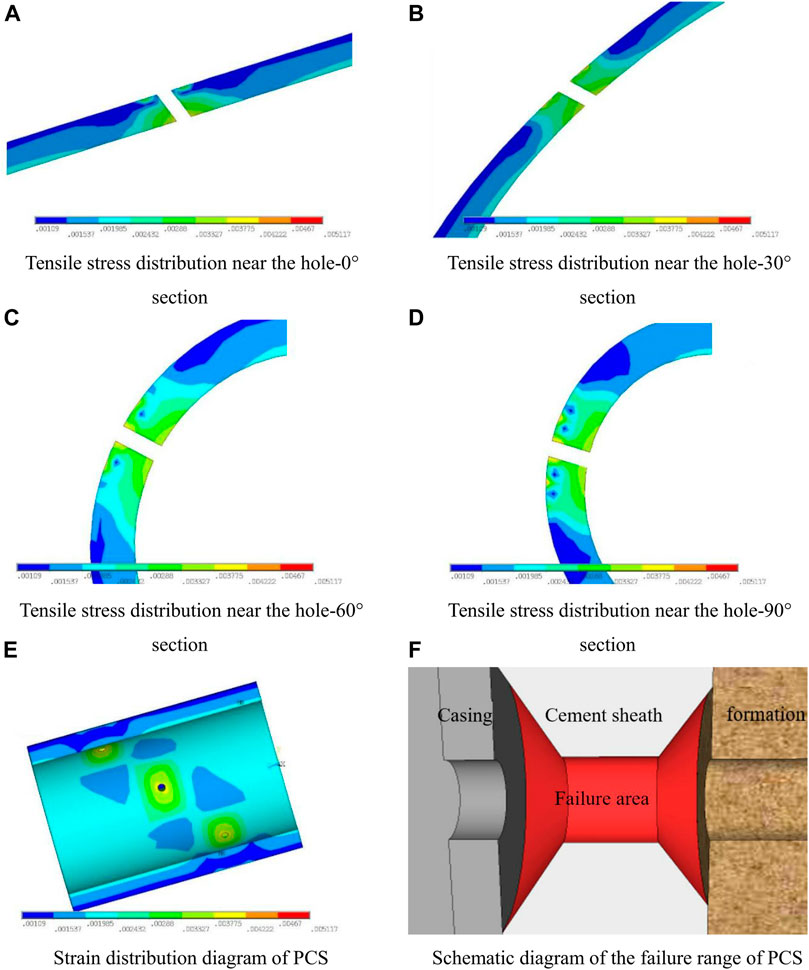
FIGURE 12. Distribution diagram of tensile stress and strain around the PH. (A) Tensile stress distribution near the hole-0 section. (B) Tensile stress distribution near the hole-30 section. (C) Tensile stress distribution near the hole-60 section. (D) Tensile stress distribution near the hole-90 section. (E) Strain distribution diagram of PCS. (F) Schematic diagram of the failure range of PCS.
5 Conclusion
This paper compares the stress state of three-dimensional CCF unperforated and perforated finite element model to obtain the influence of perforation on the SC and failure area of the cement sheath. The stress state comparison of three groups of perforation models with different hole densities and diameters verifies the SC law of perforation on the cement sheath. By studying the effects of the elastic modulus and Poisson’s ratio of the cement sheath on its maximum tensile and compressive stresses under fracturing pressure, the integrity failure form of the cement sheath and the measures for integrity failure are obtained. The research results show that, except for the SC at the perforation, the stress distribution of the perforation model is similar to that of the unperforated model, and the stress value is similar. Under fracturing conditions, the overall stress contours of the formation, casing, and cement sheath radiate outwards around the axis of the wellbore. And the inner stress is high, and the outer stress is low. The contact pressure at the cement sheath-casing interface is higher than the contact pressure at the cement sheath-formation interface and both are much greater than 0. The cementing interfaces are not debonding. The SC area is a rounded rectangle or ellipse. The SC phenomenon is more obvious in the place closer to the PH. The peak SC can reach more than twice the normal value of the stress. Under fracturing conditions, the area where the cement sheath is damaged is located at both ends of the PH, and the shape is similar to the bottom surface of the elliptical cone, the failure thickness is up to 1/2 of the thickness of the cement sheath, and the line length of the largest failure area is 4.5 times the diameter of the PH. Since the failure areas of the holes are not connected to each other and do not affect the integrity of the cement sheath as a whole, the sealing of the cement sheath is effective. Under fracturing conditions, the Poisson’s ratio of the cement sheath has little effect on its maximum compressive stress value, and its maximum tensile stress increases with the increase of Poisson’s ratio. The maximum compressive stress and maximum tensile stress of the cement sheath increase with the increase of its elastic modulus. Under fracturing conditions, the cement sheath generally undergoes tensile failure. Increasing the tensile strength of the cement sheath, reducing its elastic modulus and Poisson’s ratio can effectively prevent its tensile failure.
Data availability statement
The original contributions presented in the study are included in the article/supplementary material, further inquiries can be directed to the corresponding author.
Author contributions
YB and HL conceived and supervised the research; HY and SG performed the research; LZ and XM assisted in analyzing the data; YB, HY, and HL wrote the manuscript.
Funding
This study was funded by the Provincial Geological Exploration Fund of Guizhou Province (208-9912-JBN-UTS0).
Conflict of interest
The handling editor declared a past co-authorship with the authors HL, SG, and YB.
The author XM was employed by the Cementing Company.
The remaining authors declare that the research was conducted in the absence of any commercial or financial relationships that could be construed as a potential conflict of interest.
Publisher’s note
All claims expressed in this article are solely those of the authors and do not necessarily represent those of their affiliated organizations, or those of the publisher, the editors and the reviewers. Any product that may be evaluated in this article, or claim that may be made by its manufacturer, is not guaranteed or endorsed by the publisher.
Abbreviations
PCS, perforated cement sheath; PH, perforation hole; FEM, finite element method; CCF, casing-cement sheath-formation; SC, stress concentration.
References
Bois, A. P. P., Garnier, A., Rodot, F., Saint-Marc, J., and Aimard, N. (2011). How to prevent loss of zonal isolation through a comprehensive analysis of microannulus formation. SPE Drill. Complet. 26 (01), 13–31. doi:10.2118/124719-PA
Bu, Y., Ma, R., Guo, S., Du, J., Liu, H., and Cao, X. (2020a). A theoretical evaluation method for mechanical sealing integrity of cementing sheath. Appl. Math. Model. 84, 571–589. doi:10.1016/j.apm.2020.03.001
Bu, Y., Tian, L., Guo, B., Wang, C., and Sun, B. (2020b). Experiment and simulation on the integrity of cement ring interface in deep water shallow formation. J. Pet. Sci. Eng. 190, 107127. doi:10.1016/j.petrol.2020.107127
De Andrade, J., and Sangesland, S. (2016). Cement sheath failure mechanisms: Numerical estimates to design for long-term well integrity. J. Pet. Sci. Eng. 147, 682–698. doi:10.1016/j.petrol.2016.08.032
El-Sayed, A. A. H., and Khalaf, F. (1992). Resistance of cemented concentric casing strings under nonuniform loading. SPE Drill. Eng. 7 (01), 59–64. doi:10.2118/17927-PA
Fallahzadeh, S. H., and Rasouli, V. (2012). “The impact of cement sheath mechanical properties on near wellbore hydraulic fracture initiation,” in Paper presented at the ISRM International Symposium - EUROCK 2012.
Fan, Y., Guo, S., Gu, G., and Zhou, L. (2013). Wang, W. Research on design for ultra high hole density of perforator. Well Test. 22 (03), 65–67. doi:10.3969/j.issn.1004-4388.2013.03.022
Gray, K. E., Podnos, E., and Becker, E. (2009). Finite-element studies of near-wellbore region during cementing operations: Part i. SPE Drill. Complet. 24 (01), 127–136. doi:10.2118/106998-PA
Guo, B., Shan, L., Jiang, S., Li, G., and Lee, J. (2018). The maximum permissible fracturing pressure in shale gas wells for wellbore cement sheath integrity. J. Nat. Gas. Sci. Eng. 56, 324–332. doi:10.1016/j.jngse.2018.06.012
Guo, S., Bu, Y., Yang, X., Wang, C., Guo, B., and Sun, B. (2020). Effect of casing internal pressure on integrity of cement ring in marine shallow formation based on xfem. Eng. Fail. Anal. 108, 104258. doi:10.1016/j.engfailanal.2019.104258
Guo, Y., Blanford, M., and Candella, J. D. (2015). Evaluating the risk of casing failure caused by high-density perforation: A 3d finite-element-method study of compaction-induced casing deformation in a deepwater reservoir, gulf of Mexico. SPE Drill. Complet. 30 (02), 141–151. doi:10.2118/170618-PA
Jiapei, D., Yuhuan, B., Xuechao, C., Zhonghou, S., and Baojiang, S. (2018). Utilization of alkali-activated slag based composite in deepwater oil well cementing. Constr. Build. Mat. 186, 114–122. doi:10.1016/j.conbuildmat.2018.07.068
Lian, W., Li, J., Liu, G., and Tao, Q. (2020). Numerical simulation of cement-to-formation interface debonding during hydraulic fracturing of shale gas wells. J. Adhes. Sci. Technol. 34 (9), 1–19. doi:10.1080/01694243.2019.1688924
Liu, K., Gao, D., Zeng, J., and Wang, Z. (2018). “Study on cement sheath integrity in horizontal wells during hydraulic fracturing process,” in Paper presented at the 52nd U.S. Rock Mechanics/Geomechanics Symposium.
Lu, Y. H., Yang, S., Jin, Y., Chen, M., Yang, Y. K., Yi, Z. C., et al. (2016). “Experiments and finite element simulation on cement sheath failure in hpht well fracturing,” in Paper presented at the 50th U.S. Rock Mechanics/Geomechanics Symposium.
Luo, H., Guo, P., and Tu, L. (2010). Development for series of large diameter deep penetrating perforator. Drill. Prod. Technol. 33 (S1), 72–75.
Philippacopoulos, A. J., and Berndt, M. L. (2002). “Mechanical response and characterization of well cements,” in Paper presented at the SPE Annual Technical Conference and Exhibition.
Shen, X. (2011). “Case studies on 3-dimentional numerical prediction of critical pressure drawdown for wells in weak formations,” in Paper presented at the 45th U.S. Rock Mechanics/Geomechanics Symposium.
Smith, L. C., Smith, L. M., and Ashcroft, P. A. (2011). Analysis of environmental and economic damages from British petroleum's deepwater horizon oil spill. Albany Law Rev.
Thiercelin, M., Baumgarte, C., and Guillot, D. (1998). “A soil mechanics approach to predict cement sheath behavior,” in Paper presented at the SPE/ISRM Rock Mechanics in Petroleum Engineering.
Wang, M., Zhang, K., Ji, X., Wang, P., Ma, H., Zhang, J., et al. (2022). Molecular insight into the fluidity of cement pastes: Nano-boundary lubrication of cementitious materials. Constr. Build. Mat. 316, 125800. doi:10.1016/j.conbuildmat.2021.125800
Wang, W., and Taleghani, A. (2014). “Cement sheath integrity during hydraulic fracturing: An integrated modeling approach,” in Paper presented at the SPE Hydraulic Fracturing Technology Conference.
Wu, X., Han, L., Yang, S., Yin, F., Teodoriu, C., and Wu, X. (2019). “Numerical study on casing integrity during hydraulic fracturing shale formation,” in Paper presented at the SPE Oklahoma City Oil and Gas Symposium.
Yan, X., Jun, L., Gonghui, L., Qian, T., and Wei, L. (2018). A new numerical investigation of cement sheath integrity during multistage hydraulic fracturing shale gas wells. J. Nat. Gas. Sci. Eng. 49, 331–341. doi:10.1016/j.jngse.2017.11.027
Yan, Y., Guan, Z., Xu, Y., Yan, W., and Wang, H. (2019). Numerical investigation of perforation to cementing interface damage area. J. Pet. Sci. Eng. 179, 257–265. doi:10.1016/j.petrol.2019.04.031
Yan, Y., Guan, Z., Yan, W., and Wang, H. (2020). Mechanical response and damage mechanism of cement sheath during perforation in oil and gas well106924. J. Pet. Sci. Eng. 188. doi:10.1016/j.petrol.2020.106924
Yan, Y., Guan, Z., Zhang, B., and Chen, W. (2021). Numerical investigation of debonding extent development of cementing interfaces during hydraulic fracturing through perforation cluster. J. Pet. Sci. Eng. 197, 107970. doi:10.1016/j.petrol.2020.107970
Yang, H., Bu, Y., Guo, S., Liu, H., Du, J., and Cao, X. (2021). Effects of in-situ stress and elastic parameters of cement sheath in salt rock formation of underground gas storage on seal integrity of cement sheath. Eng. Fail. Anal. 123. doi:10.1016/j.engfailanal.2021.105258
Yao, X., Wu, Y., and Li, X. (2005). Evaluation of the key cementing technology and the properties of novel cement additives. Drill. Fluid Complet. Fluid 02, 11–16. doi:10.3969/j.issn.1001-5620.2005.02.004
Yin, F., Hou, D., Liu, W., and Deng, Y. (2019). Novel assessment and countermeasure for micro-annulus initiation of cement sheath during injection/fracturing. Fuel 252, 157–163. doi:10.1016/j.fuel.2019.04.018
Keywords: finite element method, perforated cement sheath, fracturing, stress concentration, integrity failure
Citation: Bu Y, Yang H, Zhao L, Guo S, Liu H and Ma X (2022) Stress concentration of perforated cement sheath and the effect of cement sheath elastic parameters on its integrity failure during shale gas fracturing. Front. Mater. 9:980920. doi: 10.3389/fmats.2022.980920
Received: 29 June 2022; Accepted: 28 July 2022;
Published: 29 August 2022.
Edited by:
Jiapei Du, RMIT University, AustraliaReviewed by:
Weiqing Chen, King Fahd University of Petroleum and Minerals, Saudi ArabiaMuhan Wang, Qingdao University of Technology, China
Copyright © 2022 Bu, Yang, Zhao, Guo, Liu and Ma. This is an open-access article distributed under the terms of the Creative Commons Attribution License (CC BY). The use, distribution or reproduction in other forums is permitted, provided the original author(s) and the copyright owner(s) are credited and that the original publication in this journal is cited, in accordance with accepted academic practice. No use, distribution or reproduction is permitted which does not comply with these terms.
*Correspondence: Huajie Liu, liuhuajie@upc.edu.cn
 Yuhuan Bu1,2
  Shenglai Guo
 Huajie Liu